Table of Contents
Advertisement
INSTALLATION INSTRUCTIONS AND
INSTALLER / SERVICE TECHNICIAN:
USE THE INFORMATION IN THIS MANUAL FOR THE
INSTALLATION
AND
DOCUMENT NEAR THE UNIT FOR FUTURE REFERENCE.
HOMEOWNER:
PLEASE KEEP THIS MANUAL NEAR THE FURNACE FOR
FUTURE REFERENCE.
Printed in Canada on
100% recycled paper
HOMEOWNER'S MANUAL
SERVICING
AND
KEEP
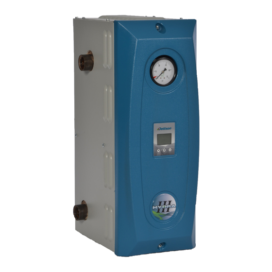
ELECTRIC BOILER
ELECTRONIC CONTROL
Models:
HYDRAT15-E2401M
HYDRAT18-E2401M
HYDRAT20-E2401M
HYDRAT24-E2401M
HYDRAT27-E2401M
HYDRAT29-E2401M
Caution:
THE
Do not tamper with the unit or
its controls. Call a qualified
service technician.
Manufactured by:
Dettson Industries Inc.
Sherbrooke, Qc, Canada
www.dettson.com
2017-10-01
III
X40248 Rev.A
Advertisement
Table of Contents

Related Manuals for Dettson HYDRAT15-E2401M


Summary of Contents for Dettson HYDRAT15-E2401M
- Page 1 DOCUMENT NEAR THE UNIT FOR FUTURE REFERENCE. its controls. Call a qualified service technician. HOMEOWNER: Manufactured by: PLEASE KEEP THIS MANUAL NEAR THE FURNACE FOR Dettson Industries Inc. FUTURE REFERENCE. Sherbrooke, Qc, Canada www.dettson.com Printed in Canada on 2017-10-01 X40248 Rev.A...
-
Page 2: Table Of Contents
Table of Contents List of Figures Figure 1: Mounting Configurations ..SAFETY Figure 2: Menu Navigation ..11 1.1 DANGER, WARNING AND CAUTION . . . Figure 3: Modulation as Function of the 1.2 IMPORTANT INFORMATION . -
Page 3: Safety
WARNING Installation and repairs performed by unqualified persons can result in hazards to them and to SAFETY others. Installations must conform to local codes or, in the absence of such codes, to codes of the country having jurisdiction. The information contained in this manual is intended for use by a qualified technician, familiar 1.1 DANGER, WARNING AND with safety procedures and who is equipped with... -
Page 4: Installation
If the heater is left unattended during the cold weather Upon completion of the installation, this manual should season, take the following precautions: be placed back into its original envelope and kept near the boiler for future reference. a) Close the main water valve in the house and purge the pipes if possible. -
Page 5: Figure 1: Mounting Configurations
Figure 1 – Mounting Configurations Table 1 – Minimum Clearances to Combustible Material Location Clearance Top (access to elements) 13 ¼" (34 cm) Sides 4" (10 cm) Bottom Front Back... -
Page 6: Distribution System
Table 2 – Circulating Pump Flow Rates Model Minimal flow 10°F 20°F USGPM (L/min) USGPM (L/min) USGPM (L/min) HYDRAT15-E2401M 5.1 (19.3) 10.2 (38.7) 5.1 (19.3) HYDRAT18-E2401M 6.1 (23.2) 12.3 (46.4) 6.1 (23.2) HYDRAT20-E2401M 6.8 (25.8) 13.6 (51.6) 6.8 (25.8) HYDRAT24-E2401M 8.2 (30.9) -
Page 7: Boiler Installation
2.5 BOILER INSTALLATION Make sure to turn off all electrical circuits when working in the appliance. At the time of installation, the following steps should be WARNING followed. Refer to Figure 5, Figure 6, Figure 7 and Figure 8. IRE HAZARD 1. -
Page 8: Operation
2.6.3 Outdoor Sensor Connection electronic control. Mount the sensor on an outside wall, protected from 3.3.2 Manual Reset High Limit Control direct sunlight, so that it will accurately measure the outside temperature. Install 2 #20 wires between the outdoor sensor and the terminals identified as EXT1 and Turn the power to the unit off before resetting the high EXT2 inside the control panel of the boiler. -
Page 9: Electronic Control
This of characters entered with function is used at the Dettson factory to test the HYDRA the three buttons of the III before it is shipped to a distributor. -
Page 10: Table 3: Alarm Description
3.4.4 Alarm 3.4.6 Dual Energy This menu is available when Some events may alter the functionality of the device in the dual energy setting is an undesired manner. These events trigger alarms in set in the installer menu. the system that remains stored in the device’s memory. This allows to manually set Reasons for alarms are: troubles with the internal or the desired energy source. -
Page 11: Figure 2: Menu Navigation
Figure 2 – Menu Navigation PUMP SET P 149.0°F TARGET 149.0°F T° IN 62.5°F T° OUT UNUSED INSTALLER INSTALLER INSTALLER -> TYPE : MAN. PASSWORD PUMP : OFF **** SET P : 149 °F T° OUT : UNUSED ↓ CONFIGURATION CONFIGURATION INSTALLER HYDRA III 20kW... -
Page 12: Figure 3: Modulation As Function Of The Outdoor Temperature
Figure 3 – Modulation as Function of the Outdoor Temperature... -
Page 13: Maintenance
It is recommended that the boiler be purged annually, in order to eliminate sediment and sludge that may have accumulated at the bottom of the boiler and covered the 4 MAINTENANCE heating elements. Procedure: 1. Let the boiler cool down; The property owner has the following responsibilities: 2. -
Page 14: Technical Data
6 TECHNICAL DATA Table 4 – Technical Specifications HYDRAT15-E2401M 15 / 11,3 63 / 54 6 / 4 HYDRAT18-E2401M 18 / 13,5 75 / 65 4 / 2 20 / 15,0 83 / 72 3 / 2 HYDRAT20-E2401M 24 / 18,0... -
Page 15: Figure 4: Boiler Components And Dimensions
Figure 4 – Boiler Components and Dimensions... -
Page 16: Figure 6: Multi-Zone Diagram With More Than One Circulator
ELECTRONIQUE CHAUDIERE ELECTRIQUE. SCHEMA D'INSTALLATION GÉNÉRAL ELECTRIC BOILER - GENERAL INSTALLATION DIAGRAM Figure 5 – Typical Diagram of a Single Zone Installation Figure 6 – Multi-zone Diagram with more than one Circulator... -
Page 17: Figure 7: Multi-Zone Diagram With Motorized Valves
Figure 7 – Multi-zone Diagram with Motorized Valves Figure 8 – Dual-Energy Installation... -
Page 18: Figure 9: Electrical Diagram
Figure 9 – Electrical Diagram... -
Page 19: Figure 10: Electrical Pannel
Figure 10 – Electrical Pannel... -
Page 20: Figure 11: Parts List
Figure 11 – Parts List... -
Page 21: Table 5: Parts List
Aquastat B04487-01 Thermodisc support assembly K03082 Relay control board Replacement kit B04474 Control support L01G011 Fuse 2A K03083 Dettson control Replacement kit L01F010 Transformer 208/240V - 24V A20015 Exterior sensor -12 C L99F007 Terminal block L01H009 Control relay 24VAC L01H030... -
Page 22: Table 7: Resistance Table Of Temperature Sensors 10K
Table 7 – Resistance Table of Temperature Sensors 10k Temp (°C) Temp (°F) Resistance ( ) Temp (°C) Temp (°F) Resistance ( ) -40.0 336 479.00 91.4 7 098.00 -38.2 314 904.00 93.2 6 808.00 -36.4 294 848.00 95.0 6 531.00 -34.6 276 194.00 96.8...
Need help?
Do you have a question about the HYDRAT15-E2401M and is the answer not in the manual?
Questions and answers