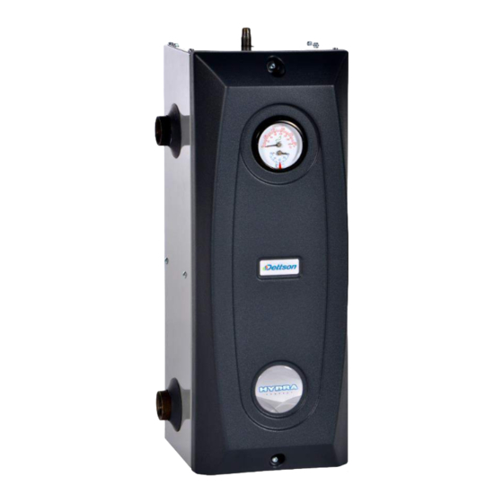
Dettson HYDRAR15-M2401M Installation Instructions And Owner's Manual
Electric boiler
mechanical control
Hide thumbs
Also See for HYDRAR15-M2401M:
Table of Contents
Advertisement
Models:
HYDRAR15-M2401M
HYDRAR18-M2401M
HYDRAR20-M2401M
HYDRAR24-M2401M
HYDRAR27-M2401M
HYDRAR29-M2401M
Attention
Do not tamper with the unit
or its controls. Call a
qualified service technician.
Manufactured by:
Dettson Industries Inc.
Sherbrooke (Québec)
Canada
www.dettson.ca
Printed in Canada on 100% recycled paper
ELECTRIC BOILER
MECHANICAL CONTROL
INSTALLER / SERVICE TECHNICIAN :
USE THE INFORMATION IN THIS MANUAL FOR THE
INSTALLATION / SERVICING OF THE BOILER AND KEEP THE
DOCUMENT NEAR THE UNIT FOR FUTURE REFERENCE.
HOMEOWNER :
PLEASE KEEP THIS MANUAL NEAR THE BOILER FOR FUTURE
REFERENCE.
2016-09-23
X40246 Rev. B
Advertisement
Table of Contents

Subscribe to Our Youtube Channel
Summary of Contents for Dettson HYDRAR15-M2401M
- Page 1 INSTALLER / SERVICE TECHNICIAN : USE THE INFORMATION IN THIS MANUAL FOR THE Manufactured by: INSTALLATION / SERVICING OF THE BOILER AND KEEP THE Dettson Industries Inc. DOCUMENT NEAR THE UNIT FOR FUTURE REFERENCE. Sherbrooke (Québec) Canada HOMEOWNER : www.dettson.ca...
-
Page 2: Table Of Contents
TABLE OF CONTENT SECTION 1 : INSTALLATION ......................3 DANGER, WARNING AND CAUTION........................3 HEATING WITH HOT WATER ..........................3 DELIVERY ................................3 INSTALLATION ..............................3 CLEARANCES ..............................4 DISTRIBUTION SYSTEM ............................. 4 INSTALLATION OF THE BOILER ........................6 ELECTRIC POWER SUPPLY ..........................6 CONNECTING THE CIRCULATING PUMP ........................ -
Page 3: Section 1 : Installation
SECTION 1 : INSTALLATION 1) DANGER, WARNING AND CAUTION 3) DELIVERY The words DANGER, WARNING and CAUTION are used to identify Upon delivery of the boiler, check the nameplate to be sure that the levels of seriousness of certain hazards. It is important that you you have received the model with the correct rating and proper understand their meaning. -
Page 4: Clearances
Figure 1: Mounting configurations 5) CLEARANCES 6) DISTRIBUTION SYSTEM The following clearances should be provided for the servicing of the The proper functioning of your heating system is directly related to the unit: quality of the plumbing installation. Therefore, the entire installation must be performed by qualified technicians. -
Page 5: Figure 2: Boiler Components
Figure 2: Boiler components... -
Page 6: Installation Of The Boiler
the High Limit protector will disconnect all the electric elements Freeze protection (when required) and a more or less frequent cycling mode will be established by the Safety Control (see the Technical Specifications Table); WARNING In order to ensure satisfactory water flow, the friction in the piping system must not exceed the capacity of the circulator;... -
Page 7: Section 2 : Operation
SECTION 2 : OPERATION Adjust the setpoint of the boiler on the aquastat. 1) ADJUSTMENTS AND START-UP Turn on the power, set the thermostat at 30C (85F). The circulator should start as well as the electrical elements in CAUTION sequence with a 8 seconds delay; The boiler must be filled with water and all air The circulator stays on for as long as there is a call for heat. -
Page 8: Section 4 : Information
SECTION 4 : INFORMATION Model: Serial number: Installation date of the electric boiler: Service telephone # – Day: Night: Dealer name and address:... -
Page 10: Section 5 : Technical Data
SECTION 5 : TECHNICAL DATA Table 2: Hydra Compact – Technical specifications HYDRAR15-M2401MA 15 11.3 NA NA NA 54 / 62 5.42 HYDRAR18-M2401MA 18 13.5 NA NA 65 / 75 HYDRAR20-M2401MA 20 15.0 NA NA 72 / 83 7.22 HYDRAR24-M2401MA 24 18.0 86 / 100 8.66... -
Page 11: Figure 3: Boiler Dimensions
Figure 3: Boiler Dimensions... -
Page 12: Figure 4: Typical Diagram Of A Single Zone Installation
Figure 4: Typical Diagram of a Single Zone Installation Figure 5: Multizone Diagram with more than one Circulator... -
Page 13: Figure 6: Multizone Diagram With Motorized Valves
Figure 6: Multizone diagram with Motorized Valves... -
Page 14: Figure 7: Electrical Diagram
Figure 7: Electrical Diagram The jumper must remain connected in order to comply with the Canadian Energy Regulations... -
Page 15: Section 6 : Replacement Parts
SECTION 6 : REPLACEMENT PARTS Figure 8: Exploded View... -
Page 16: Table 3: Parts List
Table 3: Parts list Item Description Comments B03984-03 Cover ass'y Cover, cosmetic and wiring diagram R02L006 Tridicator G11F025 Relief valve 30# 3/4m x 3/4f G08F005 Adaptator 1 x 3/4 G01G001 Standard nipple 1/4" NPT x 4" G03F001 Coppling 1/4" NPT G16G004 Cap 1/4"...


Need help?
Do you have a question about the HYDRAR15-M2401M and is the answer not in the manual?
Questions and answers