Table of Contents
Advertisement
Quick Links
INSTALLATION INSTRUCTIONS AND
INSTALLER / SERVICE TECHNICIAN:
USE THE INFORMATION IN THIS MANUAL FOR THE
INSTALLATION
AND
DOCUMENT NEAR THE UNIT FOR FUTURE REFERENCE.
HOMEOWNER:
PLEASE KEEP THIS MANUAL NEAR THE FURNACE FOR
FUTURE REFERENCE.
Printed in Canada on
100% recycled paper
HOMEOWNER'S MANUAL
SERVICING
AND
KEEP
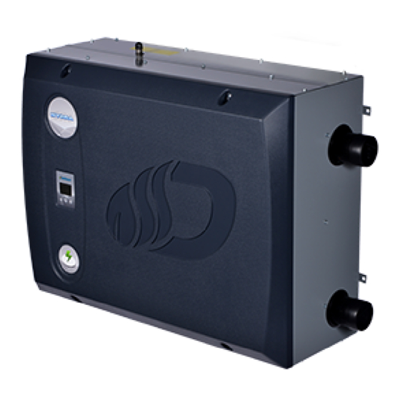
ELECTRIC BOILER
ELECTRONIC CONTROL
Models:
HYDRAI016-208-3
HYDRAI016-240-3
HYDRAI016-480-3
HYDRAI016-600-3
HYDRAI024-208-3
HYDRAI024-240-3
HYDRAI024-480-3
HYDRAI024-600-3
HYDRAI032-208-3
HYDRAI032-240-3
HYDRAI032-480-3
HYDRAI032-600-3
HYDRAI040-208-3
HYDRAI040-240-3
HYDRAI040-480-3
HYDRAI040-600-3
HYDRAI048-240-3
HYDRAI048-480-3
HYDRAI048-600-3
HYDRAI064-480-3
HYDRAI016-600-3
HYDRAI080-480-3
HYDRAI080-600-3
HYDRAI096-480-3
HYDRAI096-600-3
Caution:
THE
Do not tamper with the unit or its controls.
Call a qualified service technician.
Manufactured by:
Dettson Industries Inc.
Sherbrooke, Qc, Canada
www.dettson.com
2018-05-18
INDUSTRIAL
X40227 Rev.E
Advertisement
Table of Contents

Summary of Contents for Dettson HYDRAI016-208-3
- Page 1 Do not tamper with the unit or its controls. DOCUMENT NEAR THE UNIT FOR FUTURE REFERENCE. Call a qualified service technician. HOMEOWNER: Manufactured by: PLEASE KEEP THIS MANUAL NEAR THE FURNACE FOR Dettson Industries Inc. FUTURE REFERENCE. Sherbrooke, Qc, Canada www.dettson.com Printed in Canada on 2018-05-18 X40227 Rev.E...
-
Page 2: Table Of Contents
Table of Content List of Figures Figure 1: Mounting Configurations ..SAFETY Figure 2: Power Stealing Thermostat Resistance ....1.1 DANGER, WARNING AND CAUTION . . . 1.2 IMPORTANT INFORMATION . -
Page 3: Safety
WARNING Installation and repairs performed by unqualified persons can result in hazards to them and to SAFETY others. Installations must conform to local codes or, in the absence of such codes, to codes of the country having jurisdiction. The information contained in this manual is intended for use by a qualified technician, familiar 1.1 DANGER, WARNING AND with safety procedures and who is equipped with... -
Page 4: Installation
If the heater is left unattended during the cold weather Upon completion of the installation, this manual should season, take the following precautions: be placed back into its original envelope and kept near the boiler for future reference. a) Close the main water valve in the house and purge the pipes if possible. -
Page 5: Figure 1: Mounting Configurations
Figure 1 – Mounting Configurations Table 1 – Minimum Clearances to Combustible Material Location Clearance Top (access to elements) 13 ¼" (34 cm) Sides 4" (10 cm) Bottom Front Back... -
Page 6: Distribution System
Table 2 – Circulating Pump Flow Rates Model Minimal flow : 20°F 10°F USGPM (L/min) USGPM (L/min) HYDRAI016-XXX-3 5.8 (22.0) 10.9 (41.2) HYDRAI024-XXX-3 8.6 (32.6) 16.3 (61.8) HYDRAI032-XXX-3 11.5 (43.5) 21.8 (82.5) HYDRAI040-XXX-3 14.4 (54.5) 27.2 (103.1) HYDRAI048-XXX-3 17.3 (65.5) 32.7 (123.7) HYDRAI064-XXX-3 23.0 (87.1) -
Page 7: Boiler Installation
2.5 BOILER INSTALLATION WARNING At the time of installation, the following steps should be IRE HAZARD followed. The conductor sizing must conform to the last edition of the local or national codes. 1. Choose an appropriate location. Mount the boiler securely on the wall with the help of the mounting plate. -
Page 8: Thermostat Connection
Figure 2 – Power Stealing Thermostat Resistance the outdoor temperature, as per figure 5. 3 OPERATION 3.1 ADJUSTMENTS AND START-UP CAUTION The boiler must be filled with water and all air purged from the system, before turning on the power. the power is turned on before the boiler is filled with water, the elements will become seriously damaged. -
Page 9: Low Flow
3.7 ELECTRONIC CONTROL to the number of elements programmed in the installer menu. This function allows the building owner to reduce his peak consumption. Refer to section 3.7.2 for more Figure 4 shows how to navigate the various menus. details. 3.7.1 Display 3.5 Low Flow : State of the pump. -
Page 10: Configuration
Under no circumstances should a user try to access it. Mass, Baseboard, Light and This function is used at the Dettson factory to test the Cast Iron are pre-set values Hydra before it is shipped. -
Page 11: Figure 4: Menu Navigation
Figure 4 – Menu Navigation... -
Page 12: Figure 5: Modulation As Function Of The Outdoor Temperature
Figure 5 – Modulation as Function of the Outdoor Temperature... -
Page 13: Table 3: Alarm Description
Table 3 – Alarm Description Alarm Description Possible causes The boiler temperature Misconnected sensor T in sensor returns a temperature T in and T ext inverted that is not within standard Damaged wire values Defective sensor The outdoor temperature Misconnected sensor T out sensor returns a temperature T in and T ext inverted... -
Page 14: Maintenance
It is recommended that the boiler be purged annually, in order to eliminate sediment and sludge that may have accumulated at the bottom of the boiler and covered the 4 MAINTENANCE heating elements. Procedure: 1. Let the boiler cool down; The property owner has the following responsibilities: 2. -
Page 15: Table 4: Technical Specifications
6 TECHNICAL DATA Table 4 – Technical Specifications HYDRAI016-208-3 44.4 208V - 60Hz - 3 HYDRAI016-240-3 38.5 240V - 60Hz - 3 HYDRAI016-480-3 19.2 480V - 60Hz - 3 HYDRAI016-600-3 15.4 600V - 60Hz - 3 HYDRAI024-208-3 66.6 208V - 60Hz - 3 HYDRAI024-240-3 57.7... -
Page 16: Figure 6: Boiler Dimensions
Figure 6 – Boiler Dimensions Figure 7 – One Boiler Installation Schematic... -
Page 17: Figure 8: Multiple Boilers Installation Schematic
Figure 8 – Multiple Boilers Installation Schematic... -
Page 18: Figure 9: Parts List
Figure 9 – Parts List... -
Page 19: Table 5: Parts List
R02J015 Sensor well R02Z010 Temperature sensor R99F052 Pressure transducer R99F054 Current transducer R99G006 Rectifier relay card R99G007 Replay delay control card R99G021 Dettson controler (Industrial) R99H006 Low water cutoff X50039 Controller label X50043 Elec label 2.5" X50044 Dettson label 3.5"... -
Page 20: Figure 10: Electrical Diagram
Figure 10 – Electrical Diagram...


Need help?
Do you have a question about the HYDRAI016-208-3 and is the answer not in the manual?
Questions and answers