Table of Contents
Advertisement
Models:
HYDRAR15-E2401M
HYDRAR18-E2401M
HYDRAR20-E2401M
HYDRAR24-E2401M
HYDRAR27-E2401M
HYDRAR29-E2401M
Manufactured by:
Dettson Industries Inc
3400, Industrial Boulevard
Sherbrooke, Qc, Canada, J1L 1V8
www.dettson.ca
Attention
Do not tamper with the unit
or its controls.
qualified service technician.
Printed in Canada on 100% recycled paper
Installation Instructions
and Homeowner's Manual
INSTALLER / SERVICE TECHNICIAN :
Use the information in this manual for the installation / servicing of the
boiler and keep the document near the unit for future reference.
HOMEOWNER :
Call a
Please keep this manual near the boiler for future reference.
ELECTRIC BOILER
ELECTRONIC CONTROL
2013-09-25
C
X40218 Rev. C
Advertisement
Table of Contents

Related Manuals for Dettson HYDRAR15-E2401M


Summary of Contents for Dettson HYDRAR15-E2401M
-
Page 1: Installation Instructions
HYDRAR15-E2401M HYDRAR18-E2401M HYDRAR20-E2401M HYDRAR24-E2401M HYDRAR27-E2401M HYDRAR29-E2401M Manufactured by: Dettson Industries Inc 3400, Industrial Boulevard Sherbrooke, Qc, Canada, J1L 1V8 www.dettson.ca INSTALLER / SERVICE TECHNICIAN : Attention Use the information in this manual for the installation / servicing of the boiler and keep the document near the unit for future reference. -
Page 2: Table Of Contents
TABLE DES MATIÈRES INDEX DES TABLEAUX Table 1. Minimum clearances to combustible materials..4 Table 2. Hydra Revolution – Technical specifications...12 SECTION 1 INSTALLATION ........3 Table 3. Parts list ............18 Table 4. Parts list ............20 DANGER, WARNING AND CAUTION ....3 HEATING WITH HOT WATER ...... -
Page 3: Installation
SECTION 1 INSTALLATION DANGER, WARNING AND CAUTION INSTALLATION The words DANGER, WARNING and CAUTION are used to identify WARNING the levels of seriousness of certain hazards. It is important that you understand their meaning. You will notice these words in the manual The installation of this unit must be performed as follows: by a qualified technician and it must conform... -
Page 4: Clearances
Figure 1: Mounting configurations *The arrows represent the direction of the water flow CLEARANCES DISTRIBUTION SYSTEM The following clearances should be provided for the servicing of the The proper functioning of your heating system is directly related to unit: the quality of the plumbing installation. Therefore, the entire installation must be performed by qualified technicians. -
Page 5: Boiler Components
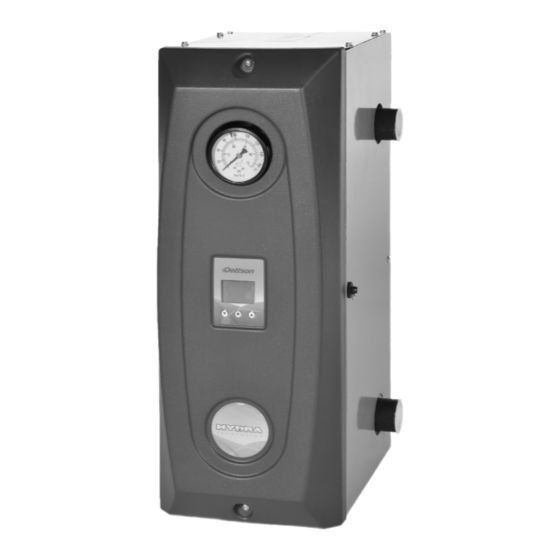
Figure 2: Boiler components Element Drain Valve, if required ¼" High Limit Sensor Water Sensor T° Thermodisc Protector Relay Element Rectifier Card Manometer High Limit Circuit Breaker 208/240VAC – 24VAC Transformator Power Card Regulator Terminal Block Freeze protection (when required) All installations must include the following items: 1 pressure regulator, adjusted to 12 psi, must be installed WARNING... -
Page 6: Figure 3
1.8.1 Connecting the Circulating Pump INSTALLATION OF THE BOILER Connect the circulating pump on 120V connections points identified At the time of installation, the following steps should be followed. N for neutral and P for controlled 120V output in the control panel as Refer to Figure 5,6,7,8 and 9. -
Page 7: Operation
SECTION 2 OPERATION Consumption: 2 ADJUSTMENTS AND START-UP The consumption menu shows an approximated value of the power consumed by the boiler since it was last reset. CAUTION Consumption is written in kilowatt The boiler must be filled with water and all air hour and time since last reset is given in hours or in days. - Page 8 Under no circumstances should a user try to access it. This function is used at the Dettson T° ext: Allows the device to know if an external factory to test the Hydra Revolution before it sensor is being used.
-
Page 9: Navigation In Menus
Figure 4: AVIGATION IN ENUS... -
Page 10: Modulation In Function Of The Exterior Temperature
Figure 5: ODULATION IN FUNCTION OF THE EXTERIOR TEMPERATURE Boiler temperature in function of outside temperature 175,0 165,0 155,0 Plinth (T_Setpoint = 175ºF) 145,0 Cast Iron (T_Setpoint = 150ºF) 135,0 Light (T_Setpoint = 125ºF) Mass (T_Setpoint = 100ºF) 125,0 115,0 105,0 95,0 85,0... -
Page 11: Section - Maintenance
3 SECTION - MAINTENANCE The property owner has the following responsibilities: It is recommended that the boiler be purged annually, in order to eliminate sediment and sludge that may have accumulated at the To maintain the area around the boiler clean at all times and bottom of the boiler and covered the heating elements. -
Page 12: Hydra Revolution - Technical Specifications
5 SECTION - TECHNICAL DATA Table 2. Hydra Revolution – Technical specifications HYDRAR15-E2401MA 11,3 54 / 62 HYDRAR18-E2401MA 13,5 65 / 75 HYDRAR20-E2401MA 15,0 72 / 83 HYDRAR24-E2401MA 18,0 86 / 100 HYDRAR27-E2401MA 20,3 97 / 112 HYDRAR29-E2401MA 21,8 104 / 120 In all cases, refer to applicable local and national codes... -
Page 13: Figure 6: Boiler Dimensions
Figure 6: Boiler Dimensions... -
Page 14: Figure 7: Typical Diagram Of A Single Zone Installation
Figure 7: Typical Diagram of a Single Zone Installation Figure 8: Multi-zone Diagram with more than one Circulator... -
Page 15: Figure 9: Multi-Zone Diagram With Motorized Valves
Figure 9: Multi-zone diagram with Motorized Valves Figure 10: Dual-energy installation... -
Page 16: Figure 11: Electrical Diagram
Figure 11: Electrical Diagram... - Page 17 6 SECTION - REMPLACEMENT PARTS Figure 12: Exploded Vue (3-4 elements)
-
Page 18: Parts List
Electrical panel Panel only B04182-01 Triac protector assembly A00421 Ext. sensor electrical wiring F14G007 Card sleeve PC .315 CBDLS525 R99G020 Dettson control 2013 Control only B04205 Electronic wiring L01F010 Transformer 208/240/120 B04184 Aquastat support assembly Aquastat, bottom and support included... -
Page 19: Figure 13: Exploded Vue (5-6 Elements)
Figure 13: Exploded Vue (5-6 elements) -
Page 20: Parts List
Electrical panel Panel only B04183-01 Triac protector assembly A00421 Ext. sensor electrical wiring F14G007 Card sleeve PC .315 CBDLS525 R99G020 Dettson control 2013 Control only B04206 Electronic kit L01F010 Transformer 208/240/120 Aquastat, bottom and support B04184 Aquastat support assembly included...
Need help?
Do you have a question about the HYDRAR15-E2401M and is the answer not in the manual?
Questions and answers