Table of Contents
Advertisement
Quick Links
Advertisement
Table of Contents

Related Manuals for Aaeon SBC-590


Summary of Contents for Aaeon SBC-590
- Page 2 This document is copyrighted 1996. All rights are reserved. AAEON Technology Inc. reserves the right to make improvements to the products described in this manual at any time without notice. No part of this manual may be reproduced, copied, translated or transmitted in any form or by any means without the prior written permission of the original manufacturer.
- Page 3 Before you begin installing your card, please make sure that the following materials have been shipped: • 1 SBC-590 CPU card • 1 6-pin mini-DIN dual outlet adapter for keyboard and PS/2 mouse • 1 Hard disk drive (IDE) interface cable (40 pin) •...
-
Page 4: Table Of Contents
Introduction ................2 Features ..................3 Specifications ................4 Board layout ................6 Card dimensions ............... 7 Jumpers and connectors ............10 Locating jumpers and connectors ..........11 Setting jumpers ................ 12 Safety precautions ..............13 Installing the CPU ..............14 Removing a CPU .............. - Page 5 IrDA Tx/Rx Header (CN1) ............. 26 Power LED and Keylock (CN2) ..........26 External Speaker (CN3) ............27 CPU cooling fan power connector (CN4) ....... 27 Hard Drive LED (CN5) ............27 Reset Switch (CN6) ..............27 Enhanced IDE (CN7, CN8) ............ 28 Floppy Drive (CN9) ..............
- Page 6 Windows 3.1x Driver Installation ........... 48 Windows 95 Installation ............49 Installation Procedure ............49 Windows NT 3.51 ..............50 Installation Procedure ............50 OS/2 Warp ................51 Installation Procedure ............51...
-
Page 8: Specifications
This chapter gives background informa- tion on the SBC-590. Sections include: • Card specifications • Board layout Chapter 1 General Information... - Page 9 Feature Connector. These features make the SBC-590 particularly suited for graphics intensive applications. Another feature of the SBC-590 is the inclusion of a high speed local bus IDE controller. This controller supports (through ATA PIO) mode 3 and mode 4 hard disks, which enables data transfer rates in excess of 11 MB/sec.
- Page 10 • Accepts Intel Pentium 75-200 MHz CPUs and other compatible CPUs at 66/60/50/40 MHz (external clock speed) • Fully PC/AT-compatible PCI/ISA-bus CPU card • On-board 32-bit PCI-bus SVGA controller • Built-in, fast PCI enhanced IDE controller; supports four IDE devices (large hard disks, CD-ROM, tape backup, etc.) •...
- Page 11 FIFO buffer. Supports speeds up to 115 Kbps. Ports can be individually configured from COM1 to COM4 or disabled. • BIOS: Award BIOS • Watchdog timer: Can generate a system reset or IRQ15. The time interval is software selectable from 1 to 64 seconds. SBC-590 User's Manual...
- Page 12 • PC/104: 104-pin connector for a 16-bit bus • DMA channels: 7 • Interrupt levels: 15 • Keyboard or PS/2 mouse connector: A 6-pin mini DIN keyboard connector is located on the mounting bracket for easy access to the keyboard and PS/2 mouse. •...
- Page 13 SBC-590 User's Manual...
- Page 14 Chapter 1 General Information...
- Page 15 SBC-590 User's Manual...
- Page 16 This chapter gives background informa- tion on the SBC-590. It explains howe to configure the card and prepare it for installation into your PC. Sections include: • Jumper settings • Safety precautions • Installing DRAM (SIMMs) Chapter 2 Installation...
-
Page 17: Jumpers And Connectors
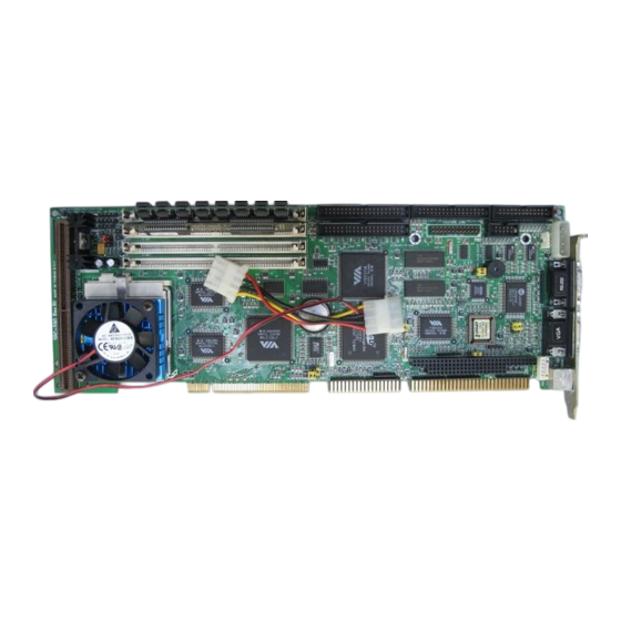
Feature connector CN11, CN13 PC/104 connector CN12 COM2 CN14 Printer Port CN15 Power connector (-5V, -12V, Gnd) CN16 VGA connector CN17 Keyboard connector CN18 COM1 CN19 Power connector (+5V, +12V, Gnd) CN20 Keyboard and PS/2 mouse connector 10 SBC-590 User's Manual... -
Page 18: Chapter 2 Installation
COMA KB/PS2 MOUSE KB CONNNECTOR PRINTER COMB PC/104 CONNECTOR FEATURE CONNECTOR FLOPPY DISK PRIMARY SECOND- ARY IDE SIMM SOCKET CACHE SOCKET Chapter 2 Installation... - Page 19 If you have any doubts about the best hardware configuration for your application, contact your local distributor or sales representa- tive before you make any changes. Generally, you simply need a standard cable to make most connections. 12 SBC-590 User's Manual...
- Page 20 Warning! Always completely disconnect the power cord from your chassis whenever you are working on it. Do not make connections while the power is on, sensitive electronic components can be damaged by the sudden rush of power. Only experienced electronics personnel should open the PC chassis.
- Page 21 The SBC-590 CPU card supports Intel Pentium 75~166 and other compatible CPUs at 66/60/50/40 MHz (external clock speed). The system's performance depends on the CPU you choose. You can install or upgrade the CPU in the board's ZIF socket by following the procedures outlined below.
- Page 22 J1. J2 must be set to match the clok ratio of CPU. The chart below shows the proper jumper setting. freq ratio = 2.5 freq ratio = 2 freq ratio = 3 freq ratio = 1.5* * default Chapter 2 Installation...
- Page 23 J3, J4 must be set to match the CPU type. The chart below shows the proper jumper setings for their respectiver Vcc: Vcc = 3.3V* Vcc = 3.45 V Vcc = 3.6 V Vcc = 3.8 V * default 16 SBC-590 User's Manual...
- Page 24 J5, J6 and J7 are set to select the CPU Clock and PCI clock. CPU clock = 40 MHz PCI clock = 20 MHz CPU clock = 50 MHz PCI clock = 25 MHz CPU clock = 60 MHz PCI clock = 30 MHz CPU clock = 66 MHz PCI clock = 33 MHz * default...
- Page 25 Be very careful that, in all cases, J9 should remain in the Normal Operation position to avoid the battery current linkage. Should you set J9 to clear CMOS, you need to put J9 back to Normal Operation before the next system boot-up. 18 SBC-590 User's Manual...
- Page 26 J10 selects PS/2 mouse enable or IRQ12 enable. *Enable PS/2 mouse Enable IRQ12 * default The internal buzzer is enabled or disabled by setting J11. *Enabled Disable *default Watchdog timer generates a system reset signal or genereartes IRQ15. *Watchdog generates the Watchdog generates IRQ15 SYSTEM RESET signal * default Refer to Appendix A, Programming the Watchdog Timer, on page...
- Page 27 COM2 uses IRQ3 COM2 uses IRQ10 * default The SBC-590 has four 72-pin SIMM (Single In-Line Memory Module) sockets that provide anywhere from 1 MB to 128 MB of DRAM. Each socket accepts from 1 to 32 MB of DRAM. For more detailed information, refer to the memory configuration tables on the following page.
- Page 28 Bank 0 Bank 1 Total Remark Memory SIMM 1 SIMM 2 SIMM 3 SIMM 4 32-bit boot up 16MB 16MB 32MB 32MB Bank O Bank 1 Total M e m o r y SIMM 1 SIMM 2 SIMM 3 SIMM 4 2 M B 4 M B 2 M B...
- Page 29 22 SBC-590 User's Manual...
- Page 30 This chapter tells how to connect periph- erals, switches and indicators to the SBC- 590 board. You can access most of the connectors from the top of the board while it is installed in the chassis. If you have a number of cards installed, or your chassis is very tight, you may need to partially remove the card to make all the connections.
- Page 31 The following table lists the connectors on the SBC-590. See Chapter 1 for help locating the connectors. Connector Function IrDA Tx/Rx header Keylock connector Speaker connector CPU fan power connector HDD LED connector RESET connector Primary IDE Secondary IDE Floppy drive...
- Page 32 Warning! Always completely disconnect the power cord from your chassis whenever you are working on it. Do not make connections while the power is on. Sensitive electronic components can be damaged by the sudden rush of power. Only experienced electronics personnel should open the PC chassis.
- Page 33 This is useful is you do not want anyone to change or stop a running program. Connect the switch between Pins 4 and 5 of CN2 Function LED power (+5V) Keyboard lock 26 SBC-590 User's Manual...
- Page 34 The CPU card has its own buzzer. You can also connect to the external speaker on your computer chassis. Pin assignments for CN3 are shown below: Function Speaker out No connection +5 VDC The CN4 is a connector for the CPU cooling fan. It provides both +5V and +12V when power is on.
- Page 35 (or blue) wire corresponds to pin 1 on the connector (on the right side). You can attach up to two floppy disk drives to the SBC-590's on- board controller. You can use any combination of 5.25" (360 KB and 1.2 MB) and 3.5"...
- Page 36 Function Function Red video C1 (blue) Green video C2 (green) Blue video C3 (red) not used C4 (2nd green) C5 (2nd blue) Red return (GND) C6 (2nd red) Green return (GND) Blue return (GND) DAC block Blank Sync return (GND) Horizontal sync Vertical sync DACWR...
- Page 37 CN14. In single-board computer (non-passive backplane) applications you will need to connect power directly to the SBC-590 board using the connector labeled POWER CON. This connector is fully compatible with the standard PC power supply connector. See the...
- Page 38 Function +12V Function -12V The SBC-590 offers two RS-232 serial ports, COM1 and COM2, which let you connect to serial devices (a mouse, printers, etc.) or a communication network. CN18 is COM1, and CN12 is COM2. D C D D S R...
- Page 39 CN20, the card's keyboard connector, is a 6-pin mini-DIN connector on the card mounting bracket. The SBC-590 also comes with an adapter to convert to a standard DIN connector and to a PS/2 mouse connector CN20 The SBC-590 provides a second connector designed for external keyboard input (CN17).
- Page 40 This chapter describes how to set the card’s BIOS configuration data. Chapter 4 Award BIOS setup...
-
Page 41: Standard Cmos Setup
This type of information is stored in battery-backed RAM so that it retains the Setup information when the power is turned off. Turning on the computer and pressing <DEL> immediately will allow you to enter Setup. 34 SBC-590 User's Manual... - Page 42 Choose the "STANDARD CMOS SETUP" option from the INITIAL SETUP SCREEN Menu, and the screen below is dis- played. This standard Setup Menu allows users to configure system components such as date, time, hard disk drive, floppy drive, display, and memory. R O M I S A B I O S (2C4L6AK1) S T A N D A R D C M O S S E T U P A W A R D S O F T W A R E , I N C .
- Page 43 Type "Y" to accept write or "N" to abort write Award Software, Inc. You can run the anti-virus program to locate the problem. If Virus Warning is Disabled, no warning message will appear if anything attempts to access the boot sector or hard disk partition. 36 SBC-590 User's Manual...
- Page 44 CPU Internal Cache/External Cache Depending on the CPU/chipset design, these options can speed up memory access when enabled. Quick Power On Self Test This option speeds up the Power-On Self Test (POST) conducted as soon as the computer is turned on. When enabled, BIOS shortens or skips some of the items during the test.
- Page 45 The system will not boot, and access to Setup will be denied if the correct password is not entered at the prompt. Setup The system will boot, but access to Setup will be denied if the correct password is not entered at the prompt. 38 SBC-590 User's Manual...
- Page 46 Note: To disable security, select PASSWORD SETTING in the main menu. At this point, you will be asked to enter a password. Simply hit the <ENTER> key to disable security. When security is disabled, the system will boot, and you can enter Setup freely. OS select for DRAM>64 MB.
- Page 47 PU/PD/+/- : Modify Set Turbo pin function : Turbo F5 : Old Values (Shift)F2 : Color Set Mouse Lock : Disabled F6 : Load BIOS Defaults Internal Flash/ROM Disk : Disabled F7 : Load Setup Defaults 40 SBC-590 User's Manual...
- Page 48 The power management setup controls the CPU board's "green" features. The following screen shows the manufacturer's default. ROM ISA BIOS (2C4L6AK1) CMOS SETUP UTILITY POWER MANAGEMENT SETUP Power Management : Enabled IRQ3 Activity : Primary Doze Timer : 32 sec IRQ4 Activity : Primary IRQ5 Activity...
- Page 49 This record is required for the system to operate. Selecting this option and pressing the [Enter] key lets you exit the Setup program without recording any new values or changing old ones. 42 SBC-590 User's Manual...
- Page 50 The SBC-590 features an on-board VGA interface. This chapter provides instruc- tions for installing and operating the software drivers on the included display driver diskette. Chapter 5 SVGA Setup...
- Page 51 OK to begin the installation. At this point the setup program locates the directory where Windows is installed. For proper operation, the drivers must be installed in the Windows subdirecto- ry. Press ENTER to complete the installation. 44 SBC-590 User's Manual...
- Page 52 If Windows 95 is not installed on the system, install it using the manufacturer’s installation procedure. In each section where the display option is selected, select VGA. 1. Double click on the My Computer icon. 2. Double click on the Display icon to bring up the Display Properties window.
- Page 53 [Test] to test that the system monito can display the selected parameters properly. 5. If an Avance Logic software driver diskette was inserted into diskette drive A earlier, remove it now. 6. To activate the new settings, restart the application. 46 SBC-590 User's Manual...
- Page 54 To install the Avance Logic software driver, perform the applica- ble steps of the following procedure. To change the resolution of the Avance Logic software driver, the refresh rate of the video screen , or the monitor make/type, perform step 3 of the following procedure.
- Page 55 System program icon. • In the System Settings dialog box, select the desired resolution and/or refresh rate and make any changes to the monitor make/type. • Perform a shutdown and reboot the system to activate the changes. 48 SBC-590 User's Manual...
- Page 56 5. Once the Avance Logic software driver is installed, to change back to the standard VGA driver, double click on the Avance Logic icon and in response to the question, “Do you want to change the VGA driver?”, press [Enter] to answer Yes (default) and the system will reinstall the standard VGA driver.
- Page 57 50 SBC-590 User's Manual...
- Page 58 Programming the Watch- dog Timer The SBC-590 is equipped with a watch- dog timer that resets the CPU or generates an interrupt if processing comes to a standstill for whatever reason. This feature ensures system reliability in industrial stand-alone and unmanned...
-
Page 59: Programming The Watchdog Timer
Step 4 Your application program task #2 Step 5 Out 443h data REM Reset the timer Step 6 in 043h, REM Disable the watchdog timer Data Values 1 sec. 2 sec. 3 sec. 4 sec. 63 sec. 52 SBC-590 User's Manual...
Need help?
Do you have a question about the SBC-590 and is the answer not in the manual?
Questions and answers