Table of Contents
Advertisement
Quick Links
The Challenge Machinery Company provides owner's manuals on its
products solely as a courtesy to its customers. See the information below
before using this manual.
These manuals are for reference only. These manuals include products which are noncurrent,
unsupported or no longer produced by The Challenge Machinery Company, and are provided solely as
an accommodation to our customers. By providing these manuals, The Challenge Machinery Company
makes no representation or warranty as to the products, their current condition, or their suitability or
fitness for use in any particular application, which are the sole and independent responsibility of the
product owner and user.
Older products may not comply with current safety procedures, guidelines or regulations, and it
is the product owner's and user's responsibility to evaluate the suitability and fitness of the
products in their current use and application. The Challenge Machinery Company makes no
representation, warranty or recommendation regarding any modifications which may be
required on non-current or unsupported products. The Challenge Machinery Company assumes
no liability for any modification or alteration to any Challenge product, and any such
modification or alteration to any Challenge product is not authorized by The Challenge
Machinery Company. The availability of these manuals is solely for the purpose of providing reference
information for the products.
This manual may not be complete in all aspects of product maintenance and repair. All products
should be used only by qualified and properly trained personnel, following proper safety
procedures. All products should be regularly inspected and maintained, and their condition, application
and use should be periodically evaluated by qualified personnel. Only qualified and properly trained
technicians should perform maintenance, repair and replacement procedures. Attempting these
procedures without proper training may cause machine damage or operator injury!
Products may be unsupported by The Challenge Machinery Company due to age or the unavailability of
parts from their original manufacturer. No parts or product support will be available to repair or maintain
unsupported products. Older products may not be UL listed (if the product does not have a UL label it is
not a listed product), and may not comply with applicable installation or other regulations or
requirements if relocated to a new facility. Many municipalities require a product to be UL listed before
an electrician will connect power to them. Often the cost of updating an older product to comply with
current safety regulations is greater than the value of the product.
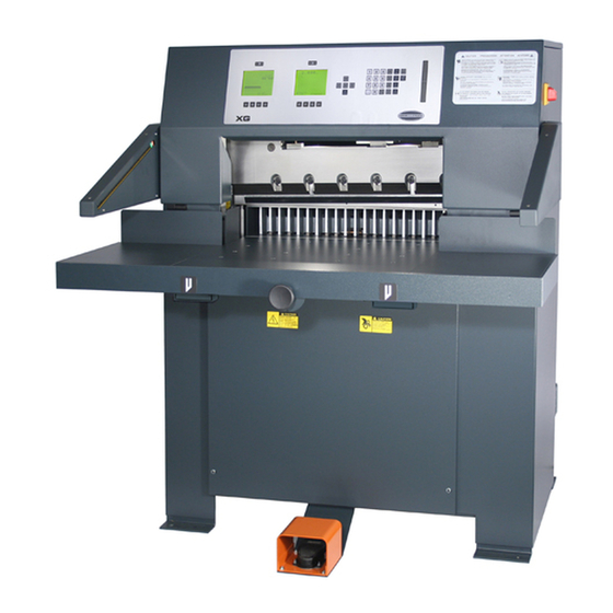
TITAN 265 XG
Operator's Manual
Serial Numbers 071755 & Up
Sold and Serviced by
The Challenge Machinery Company
6125 Norton Center Drive
Norton Shores, MI 49441-6081 USA
F.265XG-EO
ChallengeMachinery.com
January 2014
Advertisement
Table of Contents

Subscribe to Our Youtube Channel
Related Manuals for Challenge TITAN 265 XG


Summary of Contents for Challenge TITAN 265 XG
- Page 1 Products may be unsupported by The Challenge Machinery Company due to age or the unavailability of parts from their original manufacturer. No parts or product support will be available to repair or maintain unsupported products.
-
Page 2: Introduction
DIRECTLY TO CHALLENGE. If you bought a used machine, it is important to have the following information on record at Challenge. Copy this page, fill in the information and send it care of The Challenge Service Department, Norton Center Drive •... -
Page 3: Table Of Contents
1.0 Introduction TABLE OF CONTENTS 1.0 Introduction ..........................2 2.0 Safety ............................5 2.1 Precautions..........................5 2.2 Power Lockout Procedure ....................... 5 2.3 Warning Label Definitions......................6 3.0 Packing List..........................8 Optional Items ..........................8 4.0 Specifications..........................9 5.0 Installation & Setup ........................10 5.1 Inspecting Shipment...................... - Page 4 1.0 Introduction 6.12.12 Contrast Control (For Serial numbers 101877 and Above)...........27 6.13 Manual Backgauge Control ....................28 6.13.1 Backgauge Glide Control ....................28 6.13.2 Backgauge Control Knob ....................28 6.13.3 Backlash Indicator ......................28 6.14 Send Mode ..........................28 6.14.1 Entering Math .......................29 6.14.2 Entering Fractions......................29 6.15 Repeat Mode ........................29 6.16 Maintenance Mode ......................30 6.16.1 Language ........................30...
-
Page 5: Safety
2.0 Safety 2.0 Safety 2.1 Precautions • This machine is designed for one-person operation. Never operate the machine with more than one person. • Safe use of this machine is the responsibility of the operator. Use good judgment and common sense when working with and around this machine. -
Page 6: Warning Label Definitions
2.0 Safety 2.3 Warning Label Definitions The following warning labels are found at various locations on your machine. Read and understand the meaning of each symbol. If a label is lost from the machine, it should be replaced. HAZARDOUS AREA Disconnect power before cleaning, servicing, or making adjustments not requiring power. - Page 7 2.0 Safety !OJO! This Este simbolo de alerta de seguridad significa ¡ OJO ! - INSTRUCCIONES DE SEGURIDADPERSONAL. Lea las instrucciones porque se refieren a su seguridad personal. Fall de obedecer las instrucciones que siguen podria resultar en lesiones corporales. •...
-
Page 8: Packing List
3.0 Packing List 3.0 Packing List Part No. Description Qty. 2263-2 Knife 4165 Cutting Stick (in addition to one installed in machine) F.265XG-EO Operator’s Manual A-12608-4 Jogging Aid 20-2150-4 Tool Kit H-6918-608 Knife Bolts, 3/8 – 16 x 1” 8815 Knife Washers, Special 5064 Cutting Stick Puller... -
Page 9: Specifications
*With false clamp plate attached, minimum cut is 1-7/8” (48 mm). **With table, electric eyes, and footswitch removed, can be fit through a 32” (81.3 cm) door opening. Challenge reserves the right to make changes to any product or specification without notice and without incurring responsibility to existing units. -
Page 10: Installation & Setup
5.0 Installation & Setup 5.0 Installation & Setup 5.1 Inspecting Shipment This machine has been carefully packed to prevent damage during shipment. However, claims for damage or loss are the responsibility of the recipient. Inspect all shipments as soon as they are received. -
Page 11: Cleaning
5.0 Installation & Setup Figure 2 Figure 3 5.3 Cleaning After unpacking, wipe down all machine panels and clean the table surface. The display screens and control console should be cleaned using a mild water-based soap solution. DO NOT use petroleum or oil based solvents as they will damage the display screens and control console. -
Page 12: Removing The Table
5.0 Installation & Setup Now remove the two extension table support brackets (Figure 4). View from underneath table Figure 4 5.4.2 Removing the Table Make sure the knife has been removed from the machine and that the knife and clamp are in the “up” position. - Page 13 5.0 Installation & Setup Remove the preset board assembly from the bottom of table (Figure 6). Preset Board Assembly Figure 6 Open the top hood and loosen the jam nut on left hand side guide support screw and turn it in a few turns for clearance, then remove the left and right side guides as shown in Figure 7 &...
-
Page 14: Removing The Electric Eyes
5.0 Installation & Setup 5.4.3 Removing the Electric Eyes Make sure power is disconnected from the machine. Open top cover. Remove the four hex-head screws for each electric eye assembly from the inside of the machine. By sliding some of the slack in the cable through the side of the machine, the eye assemblies can be set on the machine. -
Page 15: Attaching The Electric Eyes
5.0 Installation & Setup Figure 10 5.4.7 Attaching the Electric Eyes Make sure power is disconnected from the machine. If necessary, connect the wires to the power panel. Attach electric eye assemblies with provided hardware, making sure that the bottom of the electric eye housings are parallel to the table. -
Page 16: Optional False Clamp Plate
5.0 Installation & Setup Sight Gauge Figure 11 The hydraulic fluid should be checked weekly and changed AT LEAST ONCE-PER-YEAR or after every 1,000 hours of operation. 5.6 Optional False Clamp Plate To prevent marking on pressure sensitive jobs, a false clamp plate is available as an optional item for your machine. -
Page 17: Power Hook-Up (208/230V 50/60Hz)
Test your voltage when the shop is at actual working levels. Challenge recommends a dedicated line with a lockable disconnect to provide adequate power for this machine. -
Page 18: Single Phase Hook-Up
5.0 Installation & Setup NOTE: The terminal block jumper must be set to the correct location according to the supply voltage of the machine. Failure to set the terminal block jumper will cause damage to the machine! The power source is connected to the cutter at in the junction box located at the rear, right hand side of the machine. -
Page 19: Power Hook-Up (380/400/415V 50Hz) - Also Applies For (460V 60Hz)
Test your voltage when the shop is at actual working levels. Challenge recommends a dedicated line with a lockable disconnect to provide adequate power for this machine. -
Page 20: Three Phase Hook-Up
5.0 Installation & Setup The power source is connected to the cutter at in the junction box located at the rear, right hand side of the machine. The power is then run up to the main transformer mounted to the side of the machine, under the top hood. - Page 21 5.0 Installation & Setup Line Light Adj. Screws Figure 16 To Adjust: 1. Place a wide sheet of paper on the cut stick to view the line light. 2. Using a 3/16” hex allen wrench, turn one of the cap screws until you see a 1/16-1/8” beam. NOTE: it is best to start by turning the screw clockwise.
-
Page 22: Operation
6.0 Operation IMPORTANT: DO NOT ATTEMPT TO OPERATE THE CUTTER UNTIL YOU HAVE THOROUGHLY READ AND UNDERSTAND ALL OF THE FOLLOWING INSTRUCTIONS. CALL YOUR AUTHORIZED CHALLENGE DEALER IF YOU STILL HAVE ANY QUESTIONS. 6.1 Power - Main Power Switch Figure 17 Power is brought to the machine when the main power switch is turned to the “ON”... -
Page 23: Making A Cut
6.0 Operation Clamp 5.070 Pressure >_ | | | 14 | | | ------------------------------- C) Up E) Maint D) Down F) Job H) Repeat The backgauge may now be sent to a desired position by simply typing the dimension and pressing SEND (see the “Send Mode”... -
Page 24: Adjusting The Clamp Pressure
6.0 Operation Figure 18 Figure 19 6.6 Adjusting the Clamp Pressure The clamp pressure can be adjusted by pressing soft-key “C” (Up) to increase the pressure, and soft- key “D” (Down) to decrease the pressure. The pressure scale ranges from 0 to 15, 15 being the maximum. -
Page 25: Knife Change Alarm And Lubrication Alarm
6.8 Knife Change Alarm and Lubrication Alarm The Titan 265 XG has two built in alarms that will be displayed after a certain number of cuts. The knife alarm displays a message to remind the operator to change the knife. The lube alarm displays a message to remind the operator to have the machine lubricated. -
Page 26: In/Mm Key
6.0 Operation 6.12.2 IN/MM Key This key toggles the display to show the position and programmed send values in inches (e.g. 5.250), inch fractions to the nearest 1/64” (e.g. 5_ ), or millimeters (e.g. 133.3). 6.12.3 Air Table ON/OFF Key This key turns the air table on and off. -
Page 27: Enter Key
6.0 Operation 6.12.7 Enter Key The ENTER key selects items in several modes and processes data that has been entered in the other modes. 6.12.8 Priority Add (X/Y) Key The priority/add key is used for entering fractions when they are combined with whole numbers. The symbol displayed when this key is pressed is the underline symbol “_”. -
Page 28: Manual Backgauge Control
6.0 Operation 6.13 Manual Backgauge Control 6.13.1 Backgauge Glide Control The backgauge can be moved manually by use of the backgauge glide control. Press towards the operator for forward travel and away from the operator for reverse travel. The further away from center that the actuator is pushed, the faster the backgauge will travel. -
Page 29: Entering Math
6.0 Operation 6.14.1 Entering Math In the simple send mode, the Titan 265 XG is capable of calculating an entire math string such as, 10-5+5x6+2_3/4. However, the result is limited to 29999.000 and the result cannot be a negative value. In the job mode, and during a send, the result of the calculation must be less than the backgauge limit of 30.500 inches. -
Page 30: Maintenance Mode
6.0 Operation 6.16 Maintenance Mode 5.070 Clamp MAINT MENU Pressure | | | 14 | | | LANGUAGE PARAMETERS DIAGNOSTICS KNIFE ADJUST ------------------------------- Select and press enter C) Up G) Send D) Down F) Job H) Exit The maintenance mode is an area where many machine functions can be set or modified. The four principle functions are: Language, Parameters, Diagnostic, and Knife Adjust. -
Page 31: Diagnostic
The lube alarm will also display the name and phone number of the Challenge dealer from which the machine was purchased. There are three functions within the knife count parameter: Clear Count, Knife Alarm, and Clear Lube. -
Page 32: Job Mode
F) Copy H) Exit The Titan 265 XG can be programmed for up to 99 different jobs. A job is a sequence of programmed cut positions. The backgauge moves to each position after a cut cycle is made. Each job can hold up to 99 send values. Job mode is entered by pressing soft-key “F”. When the job mode is entered, all previously programmed jobs will be displayed along with their name and lock status. -
Page 33: Lock/Unlocking A Job
6.0 Operation 6.17.1 Lock/Unlocking a Job In the Job Mode screen, the soft-key “E” will display “Lock” or “Unlock” depending on the current status of the job. If a job is locked, the word “Lock” will be displayed to the right of the job name. Locking a job prevents it from being edited. - Page 34 6.0 Operation backgauge as a send value, 3) Use the “Cut and Record” feature (described later) or 4) Use the “Sheet Division” feature. 6.17.4.2 Creating a Stock Loading Position After typing a send value, pressing the right arrow key instead of ENTER will move the cursor to the right and prompt the operator to enter a rotation indicator mark or Load Zone (LZ).
- Page 35 6.17.4.6 Sheet Division Feature The Titan 265 XG has a sheet division feature that automatically creates a complete set of send values using the parent and finished sheet sizes specified by the user. Since this feature creates an entire set of send values, it is best to use it only when creating a new job.
- Page 36 “Editing a Job” section below. 6.17.4.7 Label Cutting A label cutting feature is also provided on the Titan 265 XG. After providing the label quantity, size, and gutter, the machine will automatically create a programmed job. Begin by entering the job mode, select a job number and name (optional) then depress ENTER.
-
Page 37: Editing An Existing Job
6.0 Operation The program guides the operator through the steps of entering the necessary information. A & B are label quantities, C & D are the actual label size and E & F are gutter dimensions. Then the program asks if the columns are to be cut separate (as opposed to stacking the columns and cutting them all at once). -
Page 38: Running A Programmed Job
6.0 Operation 5.070 8.5 X 11 L # 7 Clamp 1> 8.500 Pressure 2>11.000 | | | 14 | | | Job # Lock Name Status ------------------------------- A) Division E) Insert G) Erase D) Cut & Rec F) Job H) Exit To insert a send value, press the soft-key “E”... -
Page 39: An Example Job
6.0 Operation 6.18 An Example Job The following is an example of how to program a job that will be used to make two cuts: one at 8.5” and one at 11”. 1. Turn on the machine and press CLEAR to preset the backgauge. Press the soft-key “F” (Job) to go to job mode. - Page 40 6.0 Operation Mark the gripper edge and the guide edge of printed paper and make sure the first cuts are with these guide edges against the backgauge. Measure printed paper to check for shrinkage or expansion of the paper from humidity. You may have to disregard the printed cut lines and make your own.
-
Page 41: Knife Installation/Changing
7.0 Knife Installation/Changing 7.0 Knife Installation/Changing Changing knives can be very dangerous unless safety precautions are observed and extreme care is taken when handling knives. • Make sure knife lifters are properly installed, see instructions following. • Keep handling of unprotected knives to an absolute minimum. •... - Page 42 7.0 Knife Installation/Changing Knife Adjusting Screws Figure 21 3. Remove the knife bolts from the two slotted knife bar holes and replace with the knife lifters (Figure 22). Tighten the lifters to hold the knife in place, and then remove the remaining knife bolts.
-
Page 43: Knife Installation
7.0 Knife Installation/Changing 7.2 Knife Installation Knives are heavy and always very sharp! Be sure to keep the edge away from your body and keep other people out of the area while handling the blade. Severe lacerations or dismemberment could result from careless handling procedures. 1. -
Page 44: Knife Care Tips
7.0 Knife Installation/Changing Figure 24 14. Restore power to machine and turn power on. 15. Press CLEAR. This will raise the knife and clamp to the up position. 16. Turn the power off and lockout power to machine. 17. Tighten all knife bolts securely. 18. -
Page 45: Cutting Stick
4 times again. 7.3.3 Bevel Angle Challenge recommends that bevel angles for the Titan 265 knives be in the range of 21° to 23°. In general, a 21° bevel angle will provide better cut quality when cutting soft paper (such as newsprint), recycled paper, or bound books. - Page 46 • Always keep knife bolts securely tightened. • Always use the heavy-duty knife bolt washers provided by Challenge. Failure to do so could result in scratching or marring of the clamp face. • Store knives in a dry environment to prevent corrosion.
- Page 47 7.0 Knife Installation/Changing NOTES...
-
Page 48: Oil And Grease
8.0 Oil and Grease 8.0 Oil and Grease Turn the power off and disconnect the power cord. Open the top hood for access. Parts requiring oiling are marked with red paint. See Figure 25, Figure 26, and Figure 27, for oil and grease locations. - Page 49 8.0 Oil and Grease Grease Grease Grease Grease Figure 26 – Clamp Gibs and Rack & Pinion Grease Figure 27 – Backgauge Guide...
-
Page 50: Safety Systems Test
9.0 Safety Systems Test 9.0 Safety Systems Test Machine manufacturer CHALLENGE Model TITAN 265 Serial Number __________________ Frequency of test: THESE TESTS SHOULD BE PERFORMED AT THE BEGINNING OF EACH WORK DAY. Turn the power on and press CLEAR to preset the backgauge. Make sure the knife and clamp are in the up position (if they are not, follow the instructions in this manual to send them up). - Page 51 9.0 Safety Systems Test Please enter date and initials for both tests. Date ______ ______ ______ ______ ______ ______ ______ ______ ______ ______ ______ Test 1 ______ ______ ______ ______ ______ ______ ______ ______ ______ ______ ______ Test 2 ______ ______ ______ ______ ______ ______ ______ ______ ______ ______ ______ Date ______ ______ ______ ______ ______ ______ ______ ______ ______ ______ ______ Test 1 ______ ______ ______ ______ ______ ______ ______ ______ ______ ______ ______...
- Page 52 F.265XG-EO January 2014...
Need help?
Do you have a question about the TITAN 265 XG and is the answer not in the manual?
Questions and answers