Table of Contents
Advertisement
The Challenge Machinery Company provides owner's manuals on its
products solely as a courtesy to its customers. See the information below
before using this manual.
These manuals are for reference only. These manuals include products which are noncurrent,
unsupported or no longer produced by The Challenge Machinery Company, and are provided solely as
an accommodation to our customers. By providing these manuals, The Challenge Machinery Company
makes no representation or warranty as to the products, their current condition, or their suitability or
fitness for use in any particular application, which are the sole and independent responsibility of the
product owner and user.
Older products may not comply with current safety procedures, guidelines or regulations, and it
is the product owner's and user's responsibility to evaluate the suitability and fitness of the
products in their current use and application. The Challenge Machinery Company makes no
representation, warranty or recommendation regarding any modifications which may be
required on non-current or unsupported products. The Challenge Machinery Company assumes
no liability for any modification or alteration to any Challenge product, and any such
modification or alteration to any Challenge product is not authorized by The Challenge
Machinery Company. The availability of these manuals is solely for the purpose of providing reference
information for the products.
This manual may not be complete in all aspects of product maintenance and repair. All products
should be used only by qualified and properly trained personnel, following proper safety
procedures. All products should be regularly inspected and maintained, and their condition, application
and use should be periodically evaluated by qualified personnel. Only qualified and properly trained
technicians should perform maintenance, repair and replacement procedures. Attempting these
procedures without proper training may cause machine damage or operator injury!
Products may be unsupported by The Challenge Machinery Company due to age or the unavailability of
parts from their original manufacturer. No parts or product support will be available to repair or maintain
unsupported products. Older products may not be UL listed (if the product does not have a UL label it is
not a listed product), and may not comply with applicable installation or other regulations or
requirements if relocated to a new facility. Many municipalities require a product to be UL listed before
an electrician will connect power to them. Often the cost of updating an older product to comply with
current safety regulations is greater than the value of the product.
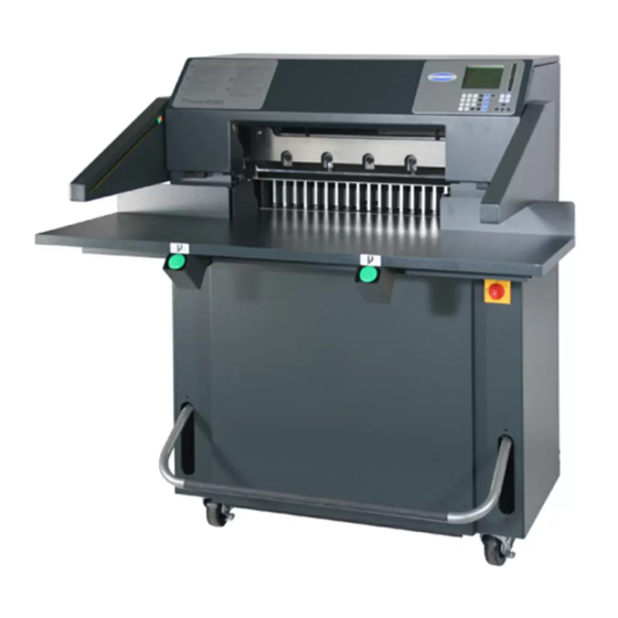
TITAN 230
Operator's Manual
Serial Numbers 070001 & Up
Sold and Serviced by
The Challenge Machinery Company
6125 Norton Center Drive
Norton Shores, MI 49441-6081 USA
F.230-O
ChallengeMachinery.com
March 2015
Advertisement
Table of Contents

Related Manuals for Challenge Titan 230


Summary of Contents for Challenge Titan 230
- Page 1 Products may be unsupported by The Challenge Machinery Company due to age or the unavailability of parts from their original manufacturer. No parts or product support will be available to repair or maintain unsupported products.
-
Page 2: Introduction
DIRECTLY TO CHALLENGE. If you bought a used machine, it is important to have the following information on record at Challenge. Copy this page, fill in the information and send it care of The Challenge Service Department 6125 Norton Center Drive ... -
Page 3: Table Of Contents
1.0 Introduction TABLE OF CONTENTS 1.0 Introduction ............................2 2.0 Safety ..............................5 2.1 Precautions ...........................5 2.2 Power Lockout Procedure ......................5 2.3 Warning Label Definitions ......................6 3.0 Packing List ............................7 4.0 Specifications ............................8 5.0 Installation & Setup ...........................9 5.1 Inspecting Shipment ........................9 5.2 Uncrating ............................9 5.3 Cleaning ............................. - Page 4 7.3.1 Knife Blade Life ........................36 7.3.2 Cutting Stick ........................37 7.3.3 Bevel Angle ......................... 37 7.3.4 Helpful Suggestions ......................37 7.3.5 Knife Care ........................... 37 8.0 Oil and Grease..........................39 9.0 Titan 230 Floor Plan ........................42 10.0 Safety Systems Test ........................43...
-
Page 5: Safety
2.0 Safety 2.0 Safety 2.1 Precautions This machine is designed for one-person operation. Never operate the machine with more than one person. Safe use of this machine is the responsibility of the operator. Use good judgment and common sense when working with and around this machine. -
Page 6: Warning Label Definitions
2.0 Safety 2.3 Warning Label Definitions The following warning labels are found at various locations on your machine. Read and understand the meaning of each symbol. If a label is lost from the machine, it should be replaced. HAZARDOUS AREA Disconnect power before cleaning, servicing, or making adjustments not requiring power. -
Page 7: Packing List
3.0 Packing List 3.0 Packing List Part No. Description Qty. 42007 Knife 42008 Cutting Stick (in addition to one installed in machine) 42014 Knife Lifter Assembly F.230-O Operator Manual A-12608-2 Jogging Aid 20-2150-7 Tool Kit 5064 Cutting Stick Puller 3/16” Allen Wrench W-130 5/32”... -
Page 8: Specifications
**For complete floor plan layout, see page 42. ***With table, elec eyes, and foot treadle removed, can be fit through a 29” (74 cm) door opening. Challenge reserves the right to make changes to any product or specification without notice and without incurring responsibility to existing units. -
Page 9: Installation & Setup
If you don’t have the ceiling clearance to do this, carefully slit the carton down the side and then unwrap it from around the cutter. Remove all lag screws from the skid. Remove the lower front cover of the Titan 230 and remove the two lag screws in the base. Remove the accessories. -
Page 10: Cleaning
5.4 Fitting Through Narrow Door The Titan 230 cutter will not fit through an opening less than 50-1/4” (128 cm) without the table being removed. With the table removed, the Titan 230 will fit through a 35” (89 cm) opening. With the table, electric eyes, and foot treadle removed, it will fit through a 29”... -
Page 11: Removing The Table
5.0 Installation & Setup 5.4.2 Removing the Table 1. Make sure the knife and clamp are in the “up” position. If they are not, read the Power Hookup section (page 16) to connect power to the machine. Turn on the power using the red and yellow main power switch and press the CLEAR button. - Page 12 5.0 Installation & Setup Motor Junction Box Cover Figure 6 9. From the rear of the machine, remove the presetter board assembly from the table (Figure 7). Presetter Board Assembly Figure 7 10. Open the top cover and remove the left and right side guides and the cut stick stops as shown in Figure 8 &...
-
Page 13: Removing The Electric Eyes
(Figure 5 & Figure 6), and all other items that were removed (See Section 5.4.2 page 11). Once the table is installed, the backgauge squareness and accuracy must be readjusted. See the Titan 230 Technical Service and Parts manual for information on how to do this. -
Page 14: Attaching The Electric Eyes
Attach electric eye assemblies with provided hardware, making sure that the bottom of the electric eye housings are parallel to the table. Once power is hooked up, the electric eyes should be checked for alignment. See the Titan 230 Technical Service and Parts manual for information on how to do this. -
Page 15: False Clamp Plate (Optional)
5.0 Installation & Setup Dip Stick Figure 11 5.6 False Clamp Plate (Optional) To prevent marking on pressure sensitive jobs, a false clamp plate is available as an optional item for your machine. This plate attaches to the bottom of the clamp. It is secured with wing nuts on studs that pass through the top of the clamp. -
Page 16: Power Hook-Up
5.0 Installation & Setup 5.7 Power Hook-Up SHOCK HAZARD! NEVER CUT THE GROUND PLUG from a three-prong plug to fit a two-prong socket. Possible shock could cause personal injury or death. Hire a qualified electrician to provide a power source that meets electrical requirements and all local electrical codes. It is the customer’s responsibility to provide a properly grounded receptacle that meets the power requirements specified on the nameplate of this machine, as well as all local electrical codes. - Page 17 5.0 Installation & Setup NOTE: If the machine is equipped with the ‘TC’ option then an additional terminal block on the back of the control console must be set for the correct supply voltage of the machine. Failure to set the terminal block (moving the wire to the correct voltage location as shown below) will cause damage to the machine! Figure 14...
-
Page 18: Operation
Parameters screen of the Maintenance Mode (section 6.12.2 on page 24). To restore power to the display and line lights, press any button on the keyboard. 6.2 Start Up Once power has been turned on, the Titan 230 will show the following display: 55.000 Backgauge must move to be preset. -
Page 19: Making A Cut
Always remove the jogging aid from the table before making a cut. A jogging aid is included as standard equipment with the Titan 230. This tool allows the operator to load and align paper without the need to place hands or arms under the knife or clamp. -
Page 20: Knife Change Alarm And Lubrication Alarm
6.5 Knife Change Alarm and Lubrication Alarm The Titan 230 has two built in alarms that will be displayed after a certain number of cuts. The knife alarm displays a message that notifies the operator to change the knife. The lube alarm displays a message that notifies the operator to have the machine lubricated. -
Page 21: Display Panel
6.0 Operation Figure 18 – Top View of Hydraulic Unit 6.8 Display Panel Display SEND Key IN/MM Key Variable Speed Pinpoint Backgauge Control Soft Keys Push-Out Key Arrow Keys Priority Add ENTER Key CLEAR Key (X/Y) Key Figure 19 6.9 Definition of Keys 6.9.1 Variable Speed Pinpoint Backgauge Control The backgauge control is used to manually position the backgauge. -
Page 22: In/Mm Key
6.0 Operation 6.9.2 IN/MM Key This key toggles the display to show the position and programmed send values in inches (e.g. 5.250), inch fractions to the nearest 1/64” (e.g. 5_ ), or millimeters (e.g. 133.3). 6.9.3 Send Key The SEND key is used to send the backgauge to any valid position. If an attempt is made to send the backgauge to an illegal position, an error message will be displayed at the bottom of the screen stating “Number outside limit”. -
Page 23: Contrast Control (Serial Numbers 080075 And Above)
6.0 Operation 6.9.11 Contrast Control (Serial Numbers 080075 and Above) The contrast of the display can be adjusted by first pushing the hidden button on the front of the control panel and using the left or right arrow keys to fine tune the contrast. 6.10 Manual Backgauge Control 6.10.1 Backgauge Glide Control The backgauge can be moved manually by use of the backgauge glide control. -
Page 24: Entering Math
6.0 Operation 6.11.1 Entering Math In the simple send mode, the Titan 230 is capable of calculating an entire math string such as, 10- 5+5x6+2_3/4. However, the result is limited to 29999.000 and the result cannot be a negative value. - Page 25 Select Clear lube to reset the lube alarm after performing the lubrication requirements as shown in the Titan 230 Technical Service and Parts manual. Note: The number of cuts needed to set off the alarm is programmed at the factory and cannot be changed.
-
Page 26: Diagnostic
6.0 Operation 6.12.3 Diagnostic The diagnostic area can be very helpful in locating a problem in the event of a machine malfunction. Use the up and down arrow keys to toggle to the desired selection, and press ENTER. See the following descriptions for an explanation of each. -
Page 27: Job Mode
6.13 Job Mode The Titan 230 can be programmed for up to 99 different jobs or channels. A job is used for making a sequence of cuts using the send (or cut) values of the job as the backgauge positions for each cut. - Page 28 6.0 Operation using the up and down arrow keys to toggle to the desired character. The numeric keys can be used to enter numbers directly into the job name. When the desired character is in place, use the right arrow key to move to the next character position. The job name can be up to 10 characters long. A letter can be removed from the job name by moving the cursor to the undesired character and pressing the CLEAR key.
-
Page 29: Editing An Existing Job
6.0 Operation When finished entering send values you may exit the current job by pressing soft-key “B” (Job) to go back to the job mode screen or soft-key “D” (Exit) to exit to send mode. Or you may use the current job for cutting by pressing the down arrow at the last line and following the instructions in the Running a Programmed Job section 6.13.6 below. -
Page 30: An Example Job
6.0 Operation Exiting a Job: To exit an open job, press the soft-key “B” (Job) to return to the job mode screen, or press the soft-key “D” (Exit) to exit to the send mode screen. 6.14 An Example Job The following is an example of how to program a job, which will be used to make two cuts: one at 8.5” and one at 11”. -
Page 31: Operating Tips
6.0 Operation 4. To enter the first send value of 8.5”, simply type in 8.5 and press ENTER. The cursor will move to the second line. Now type 11 and press enter. 5.000 1> 8.500 2> 11.000 3> _ A) Insert C) Erase B) Job D) Exit... -
Page 32: Note To Dealer
6.0 Operation Mark the gripper edge and the guide edge of printed paper and make sure the first cuts are with these guide edges against the backgauge. Measure printed paper to check for shrinkage or expansion of the paper from humidity. You may have to disregard the printed cut lines and make your own. -
Page 33: Knife Installation/Changing
7.0 Knife Installation/Changing 7.0 Knife Installation/Changing Changing knives can be very dangerous unless safety precautions are observed and extreme care is taken when handling knives. Make sure knife lifters are properly installed, see instructions following. Keep handling of unprotected knives to an absolute minimum. ... - Page 34 7.0 Knife Installation/Changing Knife Adjusting Screws Figure 22 3. Remove the knife bolts from the two slotted knife bar holes (Figure 23) and replace with the knife lifter assembly (Figure 24). Tighten the lifters to hold the knife in place, and then remove the remaining two knife bolts.
-
Page 35: Knife Installation
7.0 Knife Installation/Changing 7.2 Knife Installation Knives are heavy and always very sharp! Be sure to keep the edge away from your body and keep other people out of the area while handling the blade. Severe lacerations or dismemberment could result from careless handling procedures. 1. -
Page 36: Knife Care Tips
7.0 Knife Installation/Changing Figure 25 14. Plug in the power cord and turn the power on. 15. Press CLEAR. This will raise the knife and clamp to the up position. 16. Turn the power off and disconnect the machine power cord. 17. -
Page 37: Cutting Stick
4 times again. 7.3.3 Bevel Angle Challenge recommends that bevel angles for the Titan 230 knives be in the range of 21° to 23°. In general, a 21° bevel angle will provide better cut quality when cutting soft paper (such as newsprint), recycled paper, or bound books. - Page 38 Always keep knife bolts securely tightened. Always use the heavy duty knife bolt washers provided by Challenge. Failure to do so could result in scratching or marring of the clamp face. Store knives in a dry environment to prevent corrosion.
-
Page 39: Oil And Grease
8.0 Oil and Grease 8.0 Oil and Grease Turn the power off and disconnect the power cord. Open the top hood for access. Parts requiring oiling are marked with red paint. See figures Figure 26 through Figure 33 starting on page 39 for oil and grease locations. - Page 40 8.0 Oil and Grease Figure 28 – Knife Bar Figure 29 – Knife Bar Link – L.H. Side, Lower Figure 30 – Knife Bar Link – R.S., Lower Knife Bar Knife Cylinder Bracket, Upper...
- Page 41 8.0 Oil and Grease Figure 31 & Figure 32 –Clamp Guides Figure 33 – Leadscrew and Backgauge Guide...
-
Page 42: Titan 230 Floor Plan
9.0 Titan 230 Floor Plan 9.0 Titan 230 Floor Plan 43000-FP... -
Page 43: Safety Systems Test
10.0 Safety Systems Test Machine manufacturer CHALLENGE Model TITAN 230 Serial Number __________________ Frequency of test: THESE TESTS SHOULD BE PERFORMED AT THE BEGINNING OF EACH WORK DAY. Turn the power on and press CLEAR to preset the backgauge. Make sure the knife and clamp are in the up position (if they are not, follow the instructions in this manual to send them up). - Page 44 10.0 Safety Systems Test Please enter date and initials for both tests. Date ______ ______ ______ ______ ______ ______ ______ ______ ______ ______ ______ Test 1 ______ ______ ______ ______ ______ ______ ______ ______ ______ ______ ______ Test 2 ______ ______ ______ ______ ______ ______ ______ ______ ______ ______ ______ Date ______ ______ ______ ______ ______ ______ ______ ______ ______ ______ ______ Test 1 ______ ______ ______ ______ ______ ______ ______ ______ ______ ______ ______...
- Page 45 F.230-O March 2015...
Need help?
Do you have a question about the Titan 230 and is the answer not in the manual?
Questions and answers