Challenge Champion 305 X Operator's Manual
Serial numbers 07x1360 & up hydraulic paper cutter
Hide thumbs
Also See for Champion 305 X:
- Instructions and parts manual (132 pages) ,
- Technical service and parts manual (138 pages)
Table of Contents
Advertisement
The Challenge Machinery Company provides owner's manuals on its
products solely as a courtesy to its customers. See the information below
before using this manual.
These manuals are for reference only. These manuals include products which are noncurrent,
unsupported or no longer produced by The Challenge Machinery Company, and are provided solely as
an accommodation to our customers. By providing these manuals, The Challenge Machinery Company
makes no representation or warranty as to the products, their current condition, or their suitability or
fitness for use in any particular application, which are the sole and independent responsibility of the
product owner and user.
Older products may not comply with current safety procedures, guidelines or regulations, and it
is the product owner's and user's responsibility to evaluate the suitability and fitness of the
products in their current use and application. The Challenge Machinery Company makes no
representation, warranty or recommendation regarding any modifications which may be
required on non-current or unsupported products. The Challenge Machinery Company assumes
no liability for any modification or alteration to any Challenge product, and any such
modification or alteration to any Challenge product is not authorized by The Challenge
Machinery Company. The availability of these manuals is solely for the purpose of providing reference
information for the products.
This manual may not be complete in all aspects of product maintenance and repair. All products
should be used only by qualified and properly trained personnel, following proper safety
procedures. All products should be regularly inspected and maintained, and their condition, application
and use should be periodically evaluated by qualified personnel. Only qualified and properly trained
technicians should perform maintenance, repair and replacement procedures. Attempting these
procedures without proper training may cause machine damage or operator injury!
Products may be unsupported by The Challenge Machinery Company due to age or the unavailability of
parts from their original manufacturer. No parts or product support will be available to repair or maintain
unsupported products. Older products may not be UL listed (if the product does not have a UL label it is
not a listed product), and may not comply with applicable installation or other regulations or
requirements if relocated to a new facility. Many municipalities require a product to be UL listed before
an electrician will connect power to them. Often the cost of updating an older product to comply with
current safety regulations is greater than the value of the product.
CHAMPION 305 X, XG, XT
Operator's Manual
Serial Numbers 07X1360 & Up
Sold and Serviced by
The Challenge Machinery Company
6125 Norton Center Drive
Norton Shores, MI 49441-6081 USA
F.254-I-O
ChallengeMachinery.com
February 2014
Advertisement
Table of Contents

Related Manuals for Challenge Champion 305 X


Summary of Contents for Challenge Champion 305 X
- Page 1 Products may be unsupported by The Challenge Machinery Company due to age or the unavailability of parts from their original manufacturer. No parts or product support will be available to repair or maintain unsupported products.
-
Page 2: Introduction
Fill out the warranty card accompanying your machine and return it DIRECTLY TO CHALLENGE. If you bought a used machine, it is important to have the following information on record at Challenge. Copy this page, fill in the information and send it care of The Challenge Service Department, 6125 Norton Center Drive •... -
Page 3: Table Of Contents
1.0 Introduction TABLE OF CONTENTS 1.0 Introduction ..........................2 2.0 Safety ............................6 2.1 Precautions..........................6 2.2 Power Lockout Procedure ....................... 6 2.3 Warning Label Definitions......................7 3.0 Packing List..........................9 4.0 Specifications..........................10 5.0 Footprint............................ 11 6.0 Installation & Setup ........................12 6.1 Inspecting Shipment...................... - Page 4 1.0 Introduction 9.5.1 Backgauge Glide Control ....................27 9.5.2 IN/MM Key........................27 9.5.3 Air Table ON/OFF Key....................27 9.5.4 Send Key........................27 9.5.5 Push-Out Key .........................28 9.5.6 Clear Key........................28 9.5.7 Enter Key........................28 9.5.8 Priority Add (X/Y) Key .....................28 9.5.9 Soft Keys........................28 9.5.10 Arrow Keys ........................28 9.5.11 Contrast Control (Only on Serial numbers 10x1535 and below) ........29 9.5.12 Contrast Control (For Serial numbers 10x1536 and up)..........29 9.6 Manual Backgauge Control ....................29...
- Page 5 1.0 Introduction 13.3.4 Machine Base ......................59 14.0 Program Log ........................... 60 15.0 Channel Log..........................61 16.0 Safety System Tests ....................... 62...
-
Page 6: Safety
2.0 Safety 2.0 Safety 2.1 Precautions • This machine is designed for one-person operation. Never operate the machine with more than one person. • Safe use of this machine is the responsibility of the operator. Use good judgment and common sense when working with and around this machine. -
Page 7: Warning Label Definitions
2.0 Safety 2.3 Warning Label Definitions The following warning labels are found at various locations on your machine. Read and understand the meaning of each symbol. If a label is lost from the machine, it should be replaced. The item number and location of each label can be found in Section 17.0, Schematics and Parts List. - Page 8 2.0 Safety !OJO! This Este simbolo de alerta de seguridad significa ¡ OJO ! - INSTRUCCIONES DE SEGURIDADPERSONAL. Lea las instrucciones porque se refieren a su seguridad personal. Fall de obedecer las instrucciones que siguen podria resultar en lesiones corporales. •...
-
Page 9: Packing List
3.0 Packing List 3.0 Packing List Part No. Description Qty. Basic Machine Extension Side Tables: 47166 18 x 24 Steel Side Table 47164-1 Side Table Back Plate H-6913-606 Side Table Bolts H-6424-6 Side Table Hex Nuts H-6939-616 Leveling Screws H-6913-6008 Side Table Mounting Bolts (shipped installed) H-7321-6... -
Page 10: Specifications
Minimum space between cut positions is 0.005” or 1mm. Repeat positioning accuracy is 0.003” or 0.05mm. Electric Eyes – Response time = 68 ms Object detection capability = 12 mm Challenge reserves the right to make changes to any product or specification without notice and without incurring responsibility to existing units. -
Page 11: Footprint
5.0 Footprint 5.0 Footprint... -
Page 12: Installation & Setup
6.0 Installation & Setup 6.0 Installation & Setup 6.1 Inspecting Shipment This machine has been carefully packed to prevent damage during shipment. However, claims for damage or loss are the responsibility of the recipient. Inspect all shipments as soon as they are received. -
Page 13: Moving Instructions
A Cutter Care Kit, p/n 16077, with cleaner and wax, is available through your Authorized Challenge Dealer. The protective film on the console may be removed. Never clean console with petroleum based solvents. Damage will result. Also see, Operator Cleaning, pg. -
Page 14: Hydraulic Power Unit Removal
If installation requires that the machine pass through a doorway that is less than 49” but greater than or equal to 42” wide, the machine should have been ordered from Challenge “knocked down” with the table removed. If the machine must fit through a doorway that is less than 42” and greater than or equal to 24-1/2”, the hydraulic power unit must be removed on-site. -
Page 15: Hydraulic Check
Test line voltage when the shop is at actual working levels. Challenge recommends a dedicated line with a lockable disconnect to provide adequate power for this machine. CAUTION: SHOCK HAZARD! Always disconnect power at main power panel before working on the cutter. -
Page 16: Three Phase Hook-Up
6.0 Installation & Setup Electrical Specifications for Champion Cutters Volts Amps Circuit Size Wire Size Metric Wire 3 Phase: 460 V 11.5 20 A #12 AWG 4mm sq. 10mm sq. 10mm sq. 1 Phase: 230 16mm sq. 38.7 16mm sq. 6.9.1 Three Phase Hook-Up The power source is connected to the cutter through the bottom of the power panel (right hand side). -
Page 17: Single Phase Hook-Up
6.0 Installation & Setup 6. Press both cut buttons simultaneously to activate the motor and check to make sure it is turning the same direction as the arrow on the motor casing. If it is not turning the proper direction, disconnect the power and exchange any two leads of the power cord as in Figure 5. -
Page 18: Champion 305 Diagram
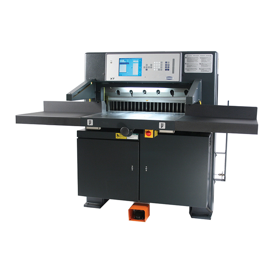
7.0 Champion 305 Diagram 7.0 Champion 305 Diagram Figure 6... -
Page 19: Operation X Model
IMPORTANT: DO NOT ATTEMPT TO OPERATE THE CUTTER UNTIL YOU HAVE THOROUGHLY READ AND UNDERSTAND ALL OF THE FOLLOWING INSTRUCTIONS. CALL YOUR AUTHORIZED CHALLENGE DEALER IF YOU STILL HAVE ANY QUESTIONS. 8.1 Power – Main Switch Power is applied to the machine when the main power switch is turned to the “ON” position (Figure 8). -
Page 20: Presetting The Backgauge
8.0 Operation X Model 8.2 Table Light The table light is turned on and off using a switch located under the arch (Figure 6, page 18). The table light will also turn on and off with the main power, provided the table light switch is in the “on” position. -
Page 21: Turning Off The Hydraulic Motor
Load and align the paper against the side guide, (Figure 10), then square it to the backgauge for cutting. Figure 10 Additional jogging aids can be purchased by contacting your authorized Challenge dealer. Always remove the jogging aid from the table before making a cut. 8.10 Pre-Clamping All Champion cutters are equipped with a low pressure clamping feature which allows the operator to clamp paper before beginning the cut cycle. -
Page 22: Adjusting The Clamp Pressure
8.0 Operation X Model 8.12 Adjusting the Clamp Pressure DO NOT set the clamp pressure below 300 psi. Pressures below this will not allow the auto-cycle to operate properly, and the knife will come down before the clamp. Severe lacerations and stock spoilage could result. A pressure reducer valve and gauge located inside the left door housing on the front of the cutter below the table. -
Page 23: Electric Eyes
8.0 Operation X Model 8.15 Electric Eyes The electric eyes prevent reaching into the cutting area while a cut is being made. If the beams are broken while a cut is being made, the knife and clamp will return to the up position. 8.16 False Clamp Plate The false clamp plate should be stored in its sheath when not in use. -
Page 24: Operation - Xg Model
IMPORTANT: DO NOT ATTEMPT TO OPERATE THE CUTTER UNTIL YOU HAVE THOROUGHLY READ AND UNDERSTAND ALL OF THE FOLLOWING INSTRUCTIONS. CALL YOUR AUTHORIZED CHALLENGE DEALER IF YOU STILL HAVE ANY QUESTIONS. 9.1 Using the Machine 9.1.1 Power - Main Power Switch Figure 11 Power is brought to the machine when the main power switch is turned to the “ON”... -
Page 25: Making A Cut
9.0 Operation – XG Model When the CLEAR key is pressed, the backgauge will move to coordinate the true position into the computer (if the knife and clamp are not in the “up” position, the display will prompt the operator to raise them by pressing the cut buttons prior to presetting the backgauge). -
Page 26: Adjusting The Clamp Pressure
The lube alarm will also display the name and phone number of the Challenge dealer from which the machine was purchased. To reset either alarm, or to change the knife alarm value, see the “Operating Controls/Maintenance Mode/Parameters/ Knife Count”... -
Page 27: Champion Xg - Display Panel
9.0 Operation – XG Model 9.4 Champion XG – Display Panel 9.5 Definition of Keys 9.5.1 Backgauge Glide Control The backgauge glide control is used to manually position the backgauge. The speed of the backgauge will depend upon where the actuator is pressed. Press farther from center for a faster speed, and closer to center for a slower speed. -
Page 28: Push-Out Key
9.0 Operation – XG Model 9.5.5 Push-Out Key The push-out key will move the backgauge forward 5 inches (or to the most forward position) and then return it to its previous position. This allows paper to be removed from the cutter without putting hands under the knife and clamp. -
Page 29: Contrast Control (Only On Serial Numbers 10X1535 And Below)
9.0 Operation – XG Model 9.5.11 Contrast Control (Only on Serial numbers 10x1535 and below) The contrast of each display screen can be adjusted by using the contrast control buttons located directly above each display screen. 9.5.12 Contrast Control (For Serial numbers 10x1536 and up) The contrast of each display is controlled by the computer if additional adjustments are needed use the following procedures;... -
Page 30: Send Mode
9.0 Operation – XG Model 9.7 Send Mode 5.070 Clamp >_ Pressure Reverse | | | 14 | | | Indicator Arrow ------------------------------- C) Up E) Maint D) Down F) Job H) Repeat The send mode is the first screen displayed after the backgauge is preset. From this screen the backgauge can be positioned with the backgauge pinpoint control or by entering a value and pressing the SEND key. -
Page 31: Repeat Mode
9.0 Operation – XG Model 9.8 Repeat Mode This mode allows the operator to make a series of cuts during which the backgauge moves a specified distance between each cut. To enter repeat mode, press soft-key “H” (Repeat). The display will then look like the one below: 5.070 Clamp Pressure... -
Page 32: Parameters
The lube alarm will also display the name and phone number of the Challenge dealer from which the machine was purchased. There are three functions within the knife count parameter: Clear Count, Knife Alarm, and Clear Lube. -
Page 33: Diagnostic
9.0 Operation – XG Model Champion XG are factory set at 2,500 cuts. However, you may want to change this value based on your specific machine applications. See the Knife section for help in choosing a knife alarm value for your machine. -
Page 34: Job Mode
9.0 Operation – XG Model 9.9.3.4 Knife Adjust The knife adjust function provides a way for the service technician to change the knife. In the Knife Adjust screen, use the up and down arrow keys to toggle to the up or down status as desired, and press ENTER. -
Page 35: Creating A New Job
9.0 Operation – XG Model 9.10.4 Creating a New Job To create a new job, type in a number that is not already assigned to a job and press ENTER (entering a job number greater than 99 will create job #99). The cursor will move to the line corresponding to the number you typed in, prompting you for a job name. - Page 36 9.0 Operation – XG Model 5.070 JOB1 Turn Indicator 1> 5.070 > < 180 Turn >> Load Zone LZ Select & Press Enter C) Up H) Exit D) Down Use Soft Keys “C” and “D” to choose a turn indicator. Pressing ENTER will place an indicator mark to the right of the send value, as shown below: 5.070 JOB1...
- Page 37 9.0 Operation – XG Model into the job as a send value. This can be very convenient for setting up a program when the actual cut positions are not known. 9.10.4.6 Sheet Division Feature The Champion XG has a sheet division feature that automatically creates a complete set of send values using the parent and finished sheet sizes specified by the user.
- Page 38 9.0 Operation – XG Model 9.10.4.7 Label Cutting A label cutting feature is also provided on the Champion XG. After providing the label quantity, size, and gutter, the machine will automatically create a programmed job. Begin by entering the job mode, select a job number and name (optional) then depress ENTER.
-
Page 39: Editing An Existing Job
9.0 Operation – XG Model 9.10.4.8 When Finished When finished entering send values you may exit the current job by pressing soft-key “B” (Job) to go back to the job mode screen or soft-key “D” (Exit) to exit to send mode. Or you may use the current job for cutting by pressing the down arrow at the last line and following the instructions in the “Running a Job”... -
Page 40: Running A Programmed Job
9.0 Operation – XG Model send value. When finished, press soft-key “D” (Cut & Rec) again to exit cut & record mode. If there is a blank line where the cursor is, press the down arrow and it will disappear. To erase a send value, press the soft-key “G”... - Page 41 9.0 Operation – XG Model 4. To enter the first send value of 8.5”, simply type in 8.5 and press ENTER. The cursor will move to the second line. Now type 11 and press enter. At this point, you could exit and save the job by pressing the soft-key “H”...
-
Page 42: Operating Tips
10.0 Operating Tips 10.0 Operating Tips Use a jogging aid to align stock. This will reduce the chance of an accident by not having to reach under the knife or clamp. Likewise, use the backgauge to push out stock before removal. Never attempt to remove paper trim clinging to the blade or clamp until they have stopped moving! Carefully lay out each sheet before you start cutting. -
Page 43: Knife Installation/Changing
11.0 Knife Installation/Changing 11.0 Knife Installation/Changing Changing knives can be very dangerous unless safety precautions are observed and extreme care is taken when handling knives. • Make sure knife lifters are properly installed, see instructions following. • Keep handling of unprotected knives to an absolute minimum. •... -
Page 44: Knife Removal
11.0 Knife Installation/Changing 11.1 Knife Removal 1. Clear the cutter table. Place chipboard directly under the knife to prevent nicking if the blade hits the table. X, XG models) On the screen menu choose “MAINT.” and then “Knife Adjust”. The menu will lead you through the rest of this step, then lock out the main power source as shown on page 6. -
Page 45: Knife Installation
11.0 Knife Installation/Changing Figure 17 7. Clear the table and put the empty knife scabbard on the table. DANGER: Used knives are heavy and still very sharp. Be careful to keep the edge away from your body and keep other people out of the area while handling the blade. -
Page 46: Using The Shielded Knife Lifter
11.0 Knife Installation/Changing 5. Grasp the knife lifters, lift the blade, and insert the blade into the knife bar slot. Slowly guide the blade into the cutter right end first, then bring the left end in parallel to the knife bar. Raise the knife into the knife bar slot as high as it will go. -
Page 47: False Clamp Plate
11.0 Knife Installation/Changing 1. After the scabbard has been placed on the front table and the scabbard screws have been removed, place your fingers along the top edge of the scabbard and your thumbs in the holes in the knife. 2. -
Page 48: Knife Care Basics
11.0 Knife Installation/Changing 2. Position the false clamp plate under the clamp, (Figure 21). The locator pegs are positioned to the rear of the cutter and are set into holes in the bottom of the clamp. Locator pegs Figure 21 3. -
Page 49: Bevel Angle
11.0 Knife Installation/Changing Nicks are visible on the cutting edge of the knife. 11.6 Bevel Angle The most appropriate bevel angle depends upon four factors. 1. The length of time desired between sharpening 2. Physical properties of the stock being cut (hardness, impurities, density) 3. -
Page 50: Knife Care
If a knife bolt is damaged, replace it. Always keep knife bolts securely tightened. Always use the heavy-duty knife bolt washers provided by Challenge. Failure to do so could result in scratching or marring of the clamp face. Store knives in a dry environment to prevent corrosion. -
Page 51: Lubrication
12.0 Lubrication 12.0 Lubrication A clean, lubricated machine will cut more accurately, run longer, with less downtime, and fewer repairs. Schedule lubrication maintenance both early in the day and early in the week. This allows the lubricants to work into the machine. Lubrication at the end of the day or week allows the lubricants to run off without any benefit to the machine. - Page 52 12.0 Lubrication Both Cylinder Pins Figure 23 Figure 24 Check bell crank and knife link pin locks to make sure they are in place and secure. Wipe down the knife bar to remove dust and debris. Figure 25...
-
Page 53: Hydraulic System
The hydraulic fluid should be changed YEARLY or EVERY 1000 HOURS of operation. The oil filter (Challenge part H-227-1) should be changed yearly or whenever any repairs are made to the hydraulic system. -
Page 54: Recommended Oils
12.0 Lubrication 12.2 Recommended Oils Use only one of the recommended oils or an ISO VG 46 Hydraulic Fluid equivalent. Oils other than the recommended type will cause seals, cups, and O-rings to deteriorate. See CAUTION below. Oil Name Distributor Rykon No. - Page 55 12.0 Lubrication 1. Make sure main power to the machine is off. 2. Remove the reservoir tank cover. 3. Using a hand drill and transfer pump commonly found at hardware and home improvement stores, transfer the used oil to empty containers. 4.
-
Page 56: Operator Adjustments/Cleaning
13.0 Operator Adjustments/Cleaning 13.0 Operator Adjustments/Cleaning 13.1 Line Lights The line light comes on whenever main power is turned to the ON position. The light from each of two bulbs reaches the table after passing between the knife and clamp, (Figure 28). Figure 28 Each light is focused with a socket head cap screw recessed into the arch, directly behind the console, (Figure 29). -
Page 57: Manual Pressure Reducer - (305X Only)
13.0 Operator Adjustments/Cleaning 4. Similarly, turn the adjustment screw of the other bulb until one, continuous beam is seen across the cut stick. Bulb replacement: 1. Make sure the power is OFF and remove key. DISCONNECT THE POWER AND LOCK IT OUT! (See Power Lockout procedure, page 6) 2. -
Page 58: Operator Cleaning
5. Apply a paste wax (Challenge P/N 16078) to the table to seal the pores of the metal. 6. Note: Do not use a wax that contains a cleaning compound on the table. The cleaner contains microscopic abrasive particles that will cause wear between the table and the bottom of the backgauge. -
Page 59: Console
5. Apply a paste wax (Challenge P/N 16078) to the table to seal the pores of the metal. 6. Note: Do not use a wax that contains a cleaning compound on the table. The cleaner contains microscopic abrasive particles that will cause wear between the table and the bottom of the backgauge. -
Page 60: Program Log
14.0 Program Log 14.0 Program Log It is always good practice to keep written records of important repeat jobs. In case a channel or the entire memory is accidentally lost. Important jobs will not have to be reprogrammed from scratch. Photocopy this page as needed to build a program log. -
Page 61: Channel Log
15.0 Channel Log 15.0 Channel Log It is recommended that you keep an abbreviated Channel Log and detailed Program Logs (copy this form) for important or repeat jobs. In the event memory capacity is reached, a glance at the Channel Log will tell you which channels may be cleared to make more room. -
Page 62: Safety System Tests
16.0 Safety System Tests 16.0 Safety System Tests Machine manufacturer CHALLENGE Model _____________ Serial Number __________________ Frequency of test: THESE TESTS SHOULD BE PERFORMED AT THE BEGINNING OF EACH WORK DAY. Turn on the cutter and start the hydraulic motor (see operator’s manual for instructions). Enable the electric eye safety system. - Page 63 16.0 Safety System Tests NOTES...
- Page 64 F.254-I-O February 2014...
Need help?
Do you have a question about the Champion 305 X and is the answer not in the manual?
Questions and answers