Table of Contents
Advertisement
Quick Links
Advertisement
Table of Contents

Related Manuals for Challenge EH-3


Summary of Contents for Challenge EH-3
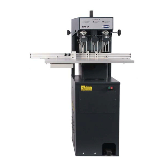
- Page 1 Challenge EH-3 Hydraulic Three Spindle Paper Drill Instruction Manual...
- Page 2 Products may be unsupported by The Challenge Machinery Company due to age or the unavailability of parts from their original manufacturer. No parts or product support will be available to repair or maintain unsupported products.
-
Page 3: Introduction
DIRECTLY TO CHALLENGE. If you bought a used machine, it is important to have the following information on record at Challenge. Copy this page, fill in the information and send it care of The Challenge Service Department, 6125 Norton Center Dr. -
Page 4: Table Of Contents
6.8 Removing the Cutting Blocks....................15 6.9 Removing the Drills from the Spindle..................15 7.0 Drilling Tips ..........................16 8.0 Accessories for Challenge Paper Drilling Machine ..............17 8.1 Genuine Challenge Hollow Drills ................... 17 8.2 Challenge Drill-Ease Lubricant Stick..................18 8.3 Challenge Drilling Blocks....................... -
Page 5: Safety
If the machine sounds or operates abnormally, turn it off and consult the Trouble Shooting section of this manual. If the problem cannot be corrected, have it checked by a qualified service person or your Authorized Challenge Dealer. • Have your electrician make sure the machine is properly grounded and that there is sufficient power to operate the machine properly. -
Page 6: Warning Label Definitions
2.0 Safety 2.3 Warning Label Definitions The following warning labels are found at various locations on your machine. Read and understand the meaning of each symbol. If a label is lost from the machine, it should be replaced HAZARDOUS AREA Disconnect power before cleaning, servicing, or making adjustments not requiring power. -
Page 7: Packing List
3.0 Packing List 3.0 Packing List Part No. Description Qty. Basic Machine 5700 Backgauge Assembly 5734 Table Assembly 5739 Waste Bin KK-281-2 Knockout, Cutting Block KK-473-3 Drill Blocks, 3” (1 dozen) CD-4-2-1/2 Hollow Drill, 1/4” CD-5-2-1/2 Hollow Drill, 5/16” K-85 Drift Hole Cover A-4950-2 Hand Drill Sharpener/Chip Remover... -
Page 8: Specifications
Net Weight (@) 525lbs 236kg Shipping Weight (@) 570lbs 257kg Electrical 208/230 Volts (+/-10%)/18Amps, 1 phase, 50/60Hz, AC. Service size: 30Amps. Challenge reserves the right to make changes to any product or specification without notice and without incurring responsibility to existing units. -
Page 9: Installation Guide
5.0 Installation Guide 5.0 Installation Guide Refer to Figure 1on this page as well as the parts lists and drawings in the back of this manual for part identification and orientation, if necessary. All guards and instruction plates are installed for your safety and information and must remain on the machine as shipped from the factory. -
Page 10: Uncrating The Paper Drill
5.0 Installation Guide 5.1 Uncrating the Paper Drill This machine is shipped on a wooden skid and is enclosed with a protective corrugated cover. It is held onto the skid with plastic straps. Remove the straps and carefully cut the corrugated cover down the side and unwrap it from around the machine. -
Page 11: Using Auto-Trip Backgauge
5.0 Installation Guide Figure 3 Pull Down Shaft Figure 4 5.2.2 Using Auto-Trip Backgauge: Attach the backgauge assembly to the table and set both sides to the 6” position (as shown in Figure 5). Next, position the table so that the front surface of the backgauge is 1-7/8” from the front of each pull down shaft (see Figure 5). -
Page 12: Installing The Drill Blocks And Drills
5.0 Installation Guide Note: Further adjustments may be necessary once the machine is ready to drill. See Table Position Adjustment (See section 9.2.1 on page 25). 5.3 Installing the Drill Blocks and Drills Always handle drills with care to avoid severe lacerations. Even dull drills are sharp enough to cause lacerations. -
Page 13: Installing The Chip Container
5.0 Installation Guide 5.6 Installing the Chip Container The chip container is installed by slipping it over the two hooks provided on the rear of the machine. -
Page 14: Operation
6.0 Operation 6.0 Operation 6.1 Starting the Machine The power for this machine is supplied by two motors; one is for the hydraulic power pack, the other is for the spindle. They are both started and stopped simultaneously by a single set of start-stop buttons located on the stand under the table (Figure 1 on page 8). -
Page 15: Setting The Backgauge Position
6.0 Operation outside of each head. This moves the heads along a shaft. A scale and pointer located at the front of the heads gives a reading in inches and millimeters of the center-line relationship to the center head. When a setting is made, make certain that the clamp knob is tightened again. Any combination of three heads can be used, that is one, two, or three holes may be drilled if desired. -
Page 16: Removing The Cutting Blocks
6.0 Operation This adjustment is made by turning the adjustable valve (located on the right side of the drilling machine stand) counterclockwise to reduce speed and clockwise to increase speed (Figure 8 on page 15). Figure 8 6.8 Removing the Cutting Blocks Each cutting block is removed by inserting your fingers in the hole provided in the frame (under the table) and pushing up on the cutting stick knock out. -
Page 17: Drilling Tips
7.0 Drilling Tips 7.0 Drilling Tips Important! To prevent the drill from overheating, always avoid drilling too slowly. The drill stroke speed should be set at the fastest speed possible that still allows the drills to cut easily through the paper. -
Page 18: Accessories For Challenge Paper Drilling Machine
8.0 Accessories for Challenge Paper Drilling Machine 8.1 Genuine Challenge Hollow Drills In 13 Standard Sizes For Every Drilling Need All drills carried in stock by local Challenge dealers (17/32” & 9/16” available by special order). Hollow Drills Diameter x Drill Capacity Cat. No. -
Page 19: Challenge Drill-Ease Lubricant Stick
CARE MUST ALWAYS BE TAKEN WHEN USING STICK AND HANDLING DRILLS. 8.3 Challenge Drilling Blocks Cat. No. KK-473-3 These Challenge 3” End-Wood Drilling Blocks are for round hole drilling operations. Sold in packages of 12. 8.4 Handi-Sharp Drill Sharpner Cat. No. 57100 Replacement Cutting Bit Part No. -
Page 20: Right Side Guide Kit
2. USE CLOCKWISE ROTATION while maintaining an even pressure, until the hollow drill is sharpened (usually two or three turns). The cutting tool seldom requires replacing, but when it does become necessary, the bit can be ordered through your Challenge Dealer (Cat. No. 4952). -
Page 21: Setting The Side Guide Stops
The automatic trip gage comes equipped with seven stops. Additional stops can be purchased at a very nominal price. Challenge fixed index gages are recommended where the same job is to be handled over and over again. They are easily and quickly attached and removed. NOTE: When drilling narrow strips, the side guide roller assembly should be mounted on the inside of the side guide assembly. -
Page 22: Two-Hand Control Kit
8.0 Accessories for Challenge Paper Drilling Machine 50-stop gage, 1/4” centers Custom patterns can also be supplied, call for details. 8.9 Two-Hand Control Kit Cat. No. A-4851-52 This 2-hand control safety kit can be installed on the EH-3D in place of the standard foot pedal control. -
Page 23: Drill Shield Kit (Standard On S/N's 135901 And Up)
8.0 Accessories for Challenge Paper Drilling Machine 8.10 Drill Shield Kit (Standard on S/N’s 135901 and up) Cat. No. 48004 Figure 15 This drill shield kit includes a clear Lexan shield that protects the operator from contacting the spinning drills. The kit can be installed on all EH-3A, EH-3B, EH-3C, and EH-3D machines. All of the... -
Page 24: Maintenance Guide
Challenge. The Challenge Machinery Company assumes no liability for any modification or alteration to any Challenge products, and any such modification or alteration to any Challenge product is not authorized by The Challenge Machinery Company. Any... -
Page 25: Routine Maintenance
9.0 Maintenance Guide 9.1 Routine Maintenance Always disconnect the power when cleaning, servicing, or lubricating your drill, see Lock Out Procedures, page 4. Production losses can be reduced if good maintenance practices are followed. The following suggestions may be helpful: 1. -
Page 26: Yearly
9.0 Maintenance Guide 2. Use only one of the recommended oils or an ISO VG 100 Hydraulic Fluid equivalent. Oils other than the recommended type will cause seals, cups and O-rings to deteriorate. See Section 9.3.1 on page 26. 9.1.4 Yearly 1. -
Page 27: Hydraulic
Through normal use, hydraulic systems gum up and seals wear. Signs of wear are hydraulic leaks and erratic operation of the vertical speed. Check with your Authorized Challenge Dealer for a current repair and/or replacement policy. Replace oil yearly. (Capacity: 1-1/2 Quarts/1.4 liters) NEVER USE Automatic Transmission oil or brake fluid as a substitute! Oils other than the recommended type will cause seals, cups and O-rings to deteriorate. - Page 28 9.0 Maintenance Guide NOTES...
- Page 29 F.352-LO January 2014...
Need help?
Do you have a question about the EH-3 and is the answer not in the manual?
Questions and answers