Challenge TITAN 200 Technical Manual
Hide thumbs
Also See for TITAN 200:
- Technical manual (84 pages) ,
- Instructions and parts manual (53 pages) ,
- Operation manual (47 pages)

Related Manuals for Challenge TITAN 200


Summary of Contents for Challenge TITAN 200
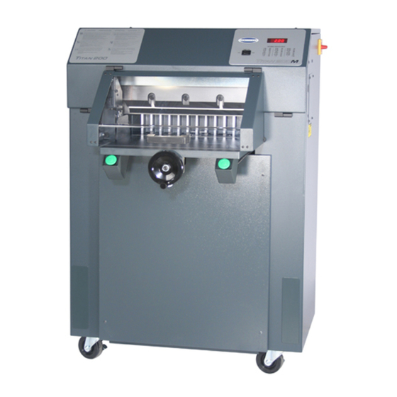
- Page 1 TECHNICAL MANUAL TITAN 200 PAPER CUTTER The Challenge Machinery Company 1433 Fulton Avenue Grand Haven, MI 49417-1594 USA Phone: 616-842-8300 Fax: 616-842-6511 TM. 200-A ChallengeMachinery.com MARCH 2000...
-
Page 2: Table Of Contents
There may be situations that are not covered by this manual. The information contained in this manual is to guide a technician to possible repair solutions. This manual is to be used in conjunction with the TITAN 200 instruction and parts manual P/N F-200 (A). TABLE OF CONTENTS TABLE OF CONTENTS.................... - Page 3 Clamp stuck down ............................27 Slow backgauge movement to end of table....................28 Hydraulic up failure ............................29 Knife down failure ............................30 Sequence error .............................. 31 Knife at both limits ............................32 Clamp down failure ............................33 Backgauge failure ............................34 Shorted key error ............................
- Page 4 SINGLE OPERATOR Do not operate with more than one person. SHOCK HAZARD Disconnect power before removing cover. Replace cover before operation SHOCK HAZARD Disconnect power before removing cover. Replace cover before operation HAZARD AREA Disconnect power before cleaning, servicing or making adjustments not requiring power.
-
Page 5: General Information
All Titan 200 s/n 981388 and down are 230vac only. If the voltage drop are 210vac or below during a cut, a buck/boost transformer, p/n K-2834, is required. Note: The buck/boost can also be rewired to buck voltage 250vac down. -
Page 6: Machine Revisions
A kit is available to keep the “F1” fuse from blowing. The kit number is K-2908. A 5A (SB) fuse is being added. The first Titan 200 with the new fuse is s/n 991734, August 99. It is located on the revised circuit board (EE-2807-1) and is labeled “FL”. -
Page 7: General Hydraulic Information
4 turns. Knife down sequence 3 turns. Clamp up sequence 1 turn. Clamp pressure reducer (adjustable by the operator) 4 turns (800 psi). Use the hydraulic pressure setting section in the manual for final adjustment. VALVE INFORMATION Listed is general information for testing and checking. VALVE CHALLENGE MANUFACTURES SPRING INNER SPOOL NUMBER NUMBER... -
Page 8: Software Revisions
SOFTWARE REVISIONS Titan 200 with front guard using EE-2762 circuit board and EE-1766-41 software. Original software. Increased knife latch timing. False Camp Plate limit was 1.750; changed it to 1.875. This revision contains all of the languages. In fraction mode corrected positioning problem. - Page 9 Titan 200 with cut buttons (N.C.) using EE-2807 circuit board and EE-1766-42 software The revision descriptions for 2.0 and on is the same as EE-1766-41 Titan 200 with cut buttons (N.O.) using EE-2807 circuit board and EE-1766-50 software Original software.
-
Page 10: Error Codes Descriptions
ERROR CODES DESCRIPTIONS ERROR MESSAGES THAT DON’T REQUIRE A FLOW CHART ERROR EXPLANATION PROCEDURE Result is Negative Math operation result was negative Press Clear key Data out of Range Send position beyond forward or reverse Press Clear key limits Send Canceled Back gauge in motion and a console key Press Clear key then Send was pressed... -
Page 11: Error Messages That Require A Flow Chart
ERRORS (NO MESSAGE) THAT REQUIRE A FLOW CHART ERROR EXPLANATION PROCEDURE Clamp stuck down Upward movement of spring return clamp See flow chart page 27 Did not overcome mechanical bind. Slow backgauge Main board is sensing the preset is always See flow chart page 28 movement to end of table activated. -
Page 12: Sensor Data Abbreviations And Meanings
Knife latch failure 1 Prox sensor on when should be off. See flow chart page 37 The pin should be in the disengaged position i.e. pulled out from under knife bar. Knife latch failure 0 Prox sensor off when should be on. See flow chart page 38 The pin should be in the engaged position i.e. -
Page 13: Titan 200 Test & Adjustment Procedures
TITAN 200 TEST & ADJUSTMENT PROCEDURES TESTING DOWN VALVE COIL MAGNETISM 1. Remove the ¾" nut holding the coil to the valve. 2. Slide the coil away from the base of the valve ¼". 3. The coil should move easily on the valve stem. -
Page 14: Manually Activating The Hydraulic Motor
MANUALLY ACTIVATING THE HYDRAULIC MOTOR Pressing the manual pin on the motor relay will activate the motor. This will raise the clamp and knife to the full up position. The relay is located on the right side center of the electrical panel. Do not push the relay for longer than 3 seconds, the main fuses may blow! 1. -
Page 15: Testing Encoder Cable
TESTING ENCODER CABLE 1. Unplug the cable connector at encoder. Measure voltages at the cable connector. 2. If voltages are correct, cable (E-2534-1) and main board (EE-2807) are good. If voltages are not correct, go to step 3. 3. With the cable connector still unpluggged at encoder, measure the voltage at the header screws. If voltage is correct the main board is good and the cable is defective. -
Page 16: Installation And Adjustments For Of The Knife Latch Assembly
TESTING AND LEVELING THE CLAMP 1. Remove the cut stick, false plate clamp if installed. Clean the bottom of the clamp. 2. Place a 2 1” x 22” strips of paper lengthwise from under the clamp (right and left), to the front edge of the table. -
Page 17: Disassembly Of Solenoid Coil Cable Connector
DISASSEMBLY OF SOLENOID COIL CABLE CONNECTOR 1. Remove screw completely from the center of square connector then remove connector from coil. 2. Unscrew cable strain relief nut. 3. Turn connector upside down. Place a small screwdriver in the narrow slot in one of the corners of the red center piece then pry it out. -
Page 18: Ee-2807 Main Board
EE-2807 MAIN BOARD... -
Page 19: Basic Machine Schematic
BASIC MACHINE SCHEMATIC... -
Page 20: Ee-2807-1
EE-2807-1... -
Page 21: Basic Hydraulic Schematic
Basic hydraulic schematic... -
Page 23: Champion And Titan Console Program Map
MACHINE CNT FALSE CLAMP PUSHOUT ACCURACY ADJ ON/OFF DIAGNOSTICS ON/OFF REPOSITION ADJUST CLAMP ERROR CODES SENSOR DATA (Titan 200 optional) ON/OFF SET MAXIMUM KNIFE CNT TIMEOUT CLEAR MEMORY yes/no SET MINIMUM KNIFE ALARM 5,10,20,30 MINUTES ELECTRIC CLAMP, on/off (Titan only) -
Page 24: Hydraulic Motor Didn't Start
Hydraulic Motor didn’t start Replace defective fuse and check tighteness of F2, F6 fuses holder. good? In the sensor data menu does RHSAFE Does Does the and LHSAFE change to "1" when each the red output led cutter have a front respective cut button is 1 lite? plexiglass guard ? -
Page 25: Positioning Error
Positioning error Test each of the choices Does the Does the backgage stop with Are the backgauge move Test another Test another no drift after the slide guide is motor brushes binding smoothly when turning the choice. choice. pressed for full speed in the holder rear pulley? then released... -
Page 26: Clamp/Knife Down
Clamp/Knife down Press "clear" then press send to remove error In the sensor data menu Check other options is KNFUP a 1 when the knife bar is at the top stroke In the In the sensor sensor data menu is HYDUP a Check other options. -
Page 27: Clamp Stuck Down
Clamp stuck down Free clamp by prying up on the side of the clamp that thats not holding paper. Place your foot on the manual clamp bar to prevent the clamp from bouncing up. Suggestions to prevent this from happening again. For following items refer to the adjustment procedure section. -
Page 28: Slow Backgauge Movement To End Of Table
Slow backgauge movement to end of table Did back gauge move to the rear after pressing "CLEAR" ? The wand must travel through sensor center and go as deep Is the Replace preset as possble without touching. preset sensor broken EE-1688-1. -
Page 29: Hydraulic Up Failure
Hydraulic up failure Is the clamp cylinder shaft at the top of stroke (5/8" or 16mm between the round actuator disc and the bottom of the cylinder)? In the Replace main sensor data menu is board the HYDUP a EE-2807-1. Is the Replace main yellow input LED... -
Page 30: Knife Down Failure
Knife down failure Did the knife move to bottom of stroke? the sensor data menu did the KNDWN Replace main board change to a 0 when the knife EE-2807-1 Is the main was at the bottom of system pressure set to stroke ? 1400 psi? Does... -
Page 31: Sequence Error
Sequence error Repower machine. If error is repeated continue on. Does the clamp Does the knife See other See other return to the top of stroke bar start down before choice. choice. before the knife bar? the clamp? Adjust clamp reducer valve CW to increase pressure. -
Page 32: Knife At Both Limits
Knife at both limits the sensor data menu did KNDWN change to a 0 when the knife bar was at the bottom of stroke? In the sensor Replace main Did the Replace main data menu is the KNFUP a 1 board, yellow LED input 9 board EE-2807-1... -
Page 33: Clamp Down Failure
Clamp down failure See Hydraulic Motor the pump turn Didn't Start flow chart Did the red LED output Replace main 2 lite and CUTSOL change to a 1 board, in the sensor data menu ? EE-2807-1 Is there 24vac Replace main between wires #42 and #35 board, at the main board? -
Page 34: Backgauge Failure
Backgauge failure Is the F1or FL fuse blown? Does the fuse Check and tighten F1 or FL blow after fuse holder. replacement? Test main board, encoder Does the and encoder cable per backgage surge then Adjust procedure stop? section. Does the back gage bind when Locate and remove mechanical bind. -
Page 35: Shorted Key Error
Shorted key error Does the console have a single beep on power After Does the the clear is console sound a single Nornal pressed does the backgauge beep after the blue keyboard cable is operation. move to the fwd or unplugged and plugged in rev limit? again? -
Page 36: Encoder Wires 9 And 10 Are Reversed" Or "Backgauge Direction Reversed
“Encoder wires 9 and 10 are reversed” or “Backgauge direction reversed” Typically errors occur after a table out installation Is black motor Is wire #17 wire connected to blue connected to H2-1 and cable wire and red motor wire wire #19 connected to H2-2 on connected to brown cable main board? wire? -
Page 37: Knife Latch Failure 1
Knife latch failure 1 See Hydraulic Motor pump turn on Didn't Start flow chart. Does the pin disengage from the knife bar? When the knife bar is at top of stroke, is there .03", Adjust bracket. 1mm, clearance from pin to knife bar? See adjustment proceduce In the sensor data... -
Page 38: Knife Latch Failure 0
Knife latch failure 0 Is the knife latch pin under the knife bar when the knife bar is at the top of stroke? Replace main Is the the sensor data Replace spring, board,EE-2807-1 return spring menu is the KNFLAT 41117 broken? a 1 ? Replace main... -
Page 39: Hydraulic Latch Error 1
Hydraulic latch error 1 See Hydraulic the pump turn Motor Didn't start flow chart Does wire #39 have a good Repair connection at main board header and the gray terminal strip? Does wire #35 have a good connection at main board H7-4 Repair header and at the gray terminal strip?
Need help?
Do you have a question about the TITAN 200 and is the answer not in the manual?
Questions and answers