Table of Contents
Advertisement
Quick Links
The Challenge Machinery Company provides owner's manuals on its
products solely as a courtesy to its customers. See the information below
before using this manual.
These manuals are for reference only. These manuals include products which are noncurrent,
unsupported or no longer produced by The Challenge Machinery Company, and are provided solely as
an accommodation to our customers. By providing these manuals, The Challenge Machinery Company
makes no representation or warranty as to the products, their current condition, or their suitability or fitness
for use in any particular application, which are the sole and independent responsibility of the product
owner and user.
Older products may not comply with current safety procedures, guidelines or regulations, and it
is the product owner's and user's responsibility to evaluate the suitability and fitness of the
products in their current use and application. The Challenge Machinery Company makes no
representation, warranty or recommendation regarding any modifications which may be required
on non-current or unsupported products. The Challenge Machinery Company assumes no liability
for any modification or alteration to any Challenge product, and any such modification or
alteration to any Challenge product is not authorized by The Challenge Machinery Company. The
availability of these manuals is solely for the purpose of providing reference information for the products.
This manual may not be complete in all aspects of product maintenance and repair. All products should
be used only by qualified and properly trained personnel, following proper safety procedures. All
products should be regularly inspected and maintained, and their condition, application and use should
be periodically evaluated by qualified personnel. Only qualified and properly trained technicians should
perform maintenance, repair and replacement procedures. Attempting these procedures without proper
training may cause machine damage or operator injury!
Products may be unsupported by The Challenge Machinery Company due to age or the unavailability of
parts from their original manufacturer. No parts or product support will be available to repair or maintain
unsupported products. Older products may not be UL listed (if the product does not have a UL label it is
not a listed product), and may not comply with applicable installation or other regulations or requirements
if relocated to a new facility. Many municipalities require a product to be UL listed before an electrician
will connect power to them. Often the cost of updating an older product to comply with current safety
regulations is greater than the value of the product.
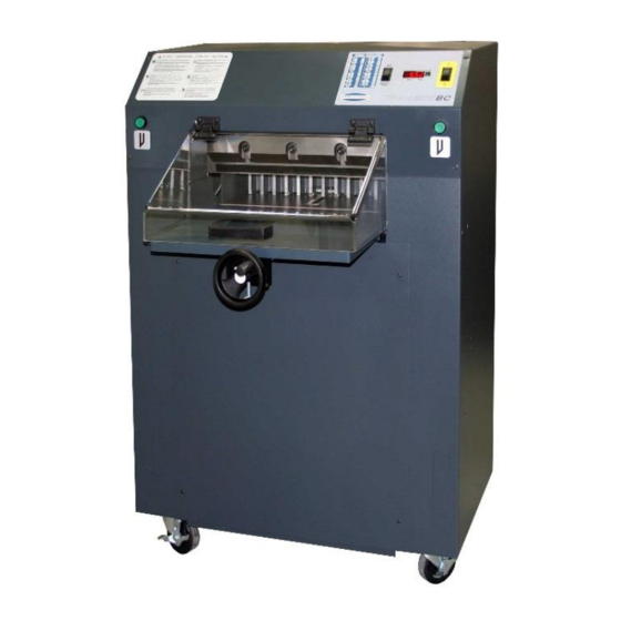
TITAN 200BC
Serial Numbers:
110001 through 159999,
200BC-A-150000 and up
Sold and Serviced by
The Challenge Machinery Company
6125 Norton Center Drive
Norton Shores, MI 49441-6081 USA
F.200BC-T
ChallengeMachinery.com
March 2018
Advertisement
Table of Contents

Related Manuals for Challenge TITAN 200BC


Summary of Contents for Challenge TITAN 200BC
- Page 1 Products may be unsupported by The Challenge Machinery Company due to age or the unavailability of parts from their original manufacturer. No parts or product support will be available to repair or maintain unsupported products.
-
Page 2: Introduction
Always give the SERIAL NUMBER and MODEL of your machine to insure the correct parts are sent as soon as possible. Challenge® is a registered trademark of The Challenge Machinery Company 6125 Norton Center Drive Norton Shores MI. 49441 Copyright© 2011 by The Challenge Machinery Company. All rights reserved. Printed in the USA... -
Page 3: Table Of Contents
4.20 K-70027 Foot Pedal Kit......................54 4.21 K-3412 Light Curtain Kit......................58 4.22 K-3431 Cut Switch Upgrade Option ..................64 4.23 Titan 200BC Floor Plan (Standard Table) ................66 4.24 Titan 200BC Floor Plan (Short Table Option) ................. 67 5.0 Safety Systems Test ........................68... -
Page 4: Safety
2.0 Safety 2.0 Safety 2.1 Precautions This machine is designed for one-person operation. Never operate the machine with more than one person. Safe use of this machine is the responsibility of the operator. Use good judgment and common sense when working with and around this machine. -
Page 5: Warning Label Definitions
2.0 Safety 2.3 Warning Label Definitions The following warning labels are found at various locations on your machine. Read and understand the meaning of each symbol. If a label is lost from the machine, it should be replaced. HAZARDOUS AREA Disconnect power before cleaning, servicing, or making adjustments not requiring power. - Page 6 2.0 Safety !OJO! This Este simbolo de alerta de seguridad significa ¡ OJO ! - INSTRUCCIONES DE SEGURIDADPERSONAL. Lea las instrucciones porque se refieren a su seguridad personal. Fall de obedecer las instrucciones que siguen podria resultar en lesiones corporales. ...
-
Page 7: Maintenance Guide
Challenge. The Challenge Machinery Company assumes no liability for any modification or alteration to any Challenge products, and any such modification or alteration to any Challenge product is not authorized by The Challenge Machinery Company. Any modification or alteration of any Challenge product... -
Page 8: Routine Maintenance
3.0 Maintenance Guide 3.1 Routine Maintenance DISCONNECT POWER before making any adjustments or lubricating. See page 4, SAFETY PRECAUTIONS, for Power Lockout Procedure. Place this machine on your plant maintenance schedule. A clean, lubricated machine will run longer, smoother, cut more accurately, with less downtime and fewer costly repairs. Schedule lubrication both early in the day and early in the week. -
Page 9: Recommended Hydraulic Oils
Empty the hydraulic tank and refill with 1 gallon of International Standards Organization Viscosity Grade 100 (ISO VG 100) rust, oxidation, and foam inhibiting hydraulic fluid (Challenge part no.: S-1991). NOTE: NEVER use automatic transmission fluid or brake fluid as a substitute for the correct hydraulic fluid. - Page 10 3.0 Maintenance Guide Grease Figure 3 – Knife Bar Links- Upper Figure 4 – Knife Bar Figure 5 – Knife Bar Link – L.H. Side, Lower...
- Page 11 3.0 Maintenance Guide Figure 6 – Knife Bar Link – R.S. Lower, Knife Bar, Knife Cylinder Bracket, Upper Figure 7 & Figure 8 –Clamp Guides Figure 9 – Lead Screw and Backgauge Guide...
-
Page 12: Adjustments
3.0 Maintenance Guide 3.4 Adjustments Several of the following tests require the machine to be operational for checking and adjusting. Be very careful that tools and other people are clear of moving parts and that the cutter is not accidentally operated while adjustments are being made. Whenever working on the machine, disconnect the power and lock it out (see SAFETY PRECAUTIONS, page 4) unless the directions specifically require the machine to be powered. -
Page 13: Squaring The Backgauge
3.0 Maintenance Guide 3.4.2 Squaring the Backgauge Figure 11 To test if the backgauge is square, place a small lift of paper against the left side of the backgauge (but not against the side guide) and make a cut. Now, leave the backgauge in the same position, flip the lift over and push it against the right side of the backgauge (but not against the side guide). -
Page 14: Lead Screw Collar
3.0 Maintenance Guide 3.4.3 Lead Screw Collar Play in the backgauge lead screw can cause inaccuracies in cutting. To remove: Turn the backgauge hand wheel clock-wise slightly, then lock the backgauge thumb screw. Loosen the collar setscrew and push the collar up tight against the pillow block while pushing the hand wheel toward the rear of the machine. - Page 15 3.0 Maintenance Guide Accuracy - If the backgauge position readout does not match the actual measurement between the knife and the backgauge, the accuracy must be reset. The accuracy can be checked by the following procedure: NOTE: The backgauge should be squared before attempting to adjust the accuracy. (See Squaring the Backgauge, page 35.) 1.
-
Page 16: Knife Latch Adjustment
3.0 Maintenance Guide 6. Run the backgauge back then bring it forward through the 5”/127mm preset again and make another test. Continue to adjust and preset until your test sheets are equal. 3.4.5 Knife Latch Adjustment If the hydraulic motor switches on and the tilt shield interlock switch is adjusted properly, but the machine will not cycle, then the knife latch needs to be adjusted. - Page 17 3.0 Maintenance Guide 2. Knife Down Sequence Pressure — 900 psi. 3. Clamp/Knife up Sequence Pressure — 600 psi. 4. Clamp Pressure Reducer — 400-800 psi. Notes: To access hydraulic gauges and valves, remove the lower front cover panel. ...
-
Page 18: Cleaning
3.0 Maintenance Guide 3.5 Cleaning Before cleaning inside machine, turn off and lockout power, page 4. Hydraulics The hydraulic manifold, fittings, and hoses should be wiped off weekly to maintain maximum cooling. Remove then replace covers as necessary. Table 1. The front table should be wiped down periodically. Use a non-abrasive cleaner along with a protective wax. - Page 19 3.0 Maintenance Guide NOTES...
-
Page 20: Schematics & Parts Lists
4.0 Schematics & Parts Lists 4.0 Schematics & Parts Lists 4.1 70000 Main Assembly – Knife/Clamp... - Page 21 4.0 Schematics & Parts Lists 70000 Main Assembly – Knife/Clamp Parts List PART NO. DESCRIPTION 8815 WASHER - 3/8 HEAVY 10001-1 BASE 10002-2 FRONT GUIDE 10002-3 REAR GUIDE 10003 KNIFE BAR 10004-3 CLAMP - 20" 10007-2 ARCH 10008 LINK- KNIFE BAR 10009 PIN- LINK 10010...
-
Page 22: 70000 Main Assembly - Arch
4.0 Schematics & Parts Lists 4.2 70000 Main Assembly – Arch... - Page 23 4.0 Schematics & Parts Lists 70000 Main Assembly – Arch Parts List PART NO. DESCRIPTION 10004-3 CLAMP 10007-2 ARCH 11288-38 WASHER/SPACER 43034 ACTUATOR- CLAMP UP E-866-4 MICROSWITCH EE-3416 POWER PANEL W/HOOD EE-3442 POWER PANEL W/EYES H-6918-610 SCREW - 3/8-16 X 1-1/4 SOCKET HEAD CAP H-7327-12 WASHER - 3/8 MEDIUM LOCK...
-
Page 24: 70000 Main Assembly - Table
4.0 Schematics & Parts Lists 4.3 70000 Main Assembly – Table... - Page 25 4.0 Schematics & Parts Lists 70000 Main Assembly – Table Parts List PART NO. DESCRIPTION 4166 PLASTIC CUTTING STICK 8641 ACTUATOR- PRESET 8826-1 3/4-8 4-START ACME NUT 10025-2 TABLE 10026-5 PILLOW BLOCK- MIDDLE 10026-7 PILLOW BLOCK 10027-1 BRACKET - BACKGAGE 10028-2 GUIDE- BACKGAUGE BRACKET 10031-2...
- Page 26 4.0 Schematics & Parts Lists H-6947-405 SCREW - 1/4-20 X 5/8 FULL DOG POINT SOC SET H-6968-102408 SCREW - #10-24 X 1/2 NYLOK SOC SET H-6974-416 SCREW - 1/4-28 X 1 BRASS TIP SET H-7321-5 WASHER - 5/16 SAE PLAIN H-7321-6 WASHER - 3/8 SAE PLAIN H-21S-187-0750...
- Page 27 4.0 Schematics & Parts Lists NOTES...
-
Page 28: 70000 Main Assembly - Knife Latch
4.0 Schematics & Parts Lists 4.4 70000 Main Assembly – Knife Latch... - Page 29 4.0 Schematics & Parts Lists 70000 Main Assembly – Knife Latch Parts List PART NO. DESCRIPTION 8815 WASHER - KNIFE SCREWS 10002-2 FRONT GUIDE 41120-4 ASSEMBLY- KNIFE LATCH E-866-4 MICROSWITCH H-6423-#4 NUT - #4-40 HEX KEP H-6918-102406 SCREW - #10-24 X 3/4 SOCKET HEAD CAP H-6923-44012 SCREW - #4-40 X 3/4 ROUND HD MACH H-7321-#10...
-
Page 30: 70000 Main Assembly - Console/Tilt Shield
4.0 Schematics & Parts Lists 4.5 70000 Main Assembly – Console/Tilt Shield... - Page 31 SCREW - #10-24 X 1/2 BUTTON HEAD CAP H-6910-406 SCREW - 1/4-20 X 3/4 BUTTON HEAD CAP H-6923-44012 SCREW - #4-40 X 3/4 ROUND HD MACH H-7324-#4 WASHER - #4 INT TOOTH S-1694 TYRAP S-1781-116 LABEL- WARNING S-1781-202 CONSOLE LABEL- TITAN 200BC...
-
Page 32: 70000 Main Assembly - Stand
4.0 Schematics & Parts Lists 4.6 70000 Main Assembly – Stand... - Page 33 4.0 Schematics & Parts Lists 70000 Main Assembly – Stand Parts List PART NO. DESCRIPTION 40016-8 MOUNT - VIBRATION 41014 SWIVEL CASTER WITH BRAKE 42057-1 FOOT BRACKET 44084 JACKSCREW - TABLE 51036 FOOT 70100 STAND WELDMENT - TITAN 200 71009 HYD.
-
Page 34: 70000 Main Assembly - Covers
4.0 Schematics & Parts Lists 4.7 70000 Main Assembly – Covers... - Page 35 4.0 Schematics & Parts Lists 70000 Main Assembly – Covers Parts List PART NO. DESCRIPTION 14050 SERIAL PLATE 43041-2 COVER- REAR STAND (TOP) 43044-1 COVER- REAR STAND 70022 LOWER FRONT COVER 70023-1 TOP COVER 70024 BACKGAUGE COVER- SHEET METAL 70100 STAND WELDMENT - TITAN 200 H-6910-102404 SCREW - #10-24 X 1/2 BUTTON HEAD CAP...
-
Page 36: 70000 Main Assembly - Short Table Option
4.0 Schematics & Parts Lists 4.8 70000 Main Assembly – Short Table Option... - Page 37 4.0 Schematics & Parts Lists 70000 Main Assembly – Short Table Option Parts List PART NO. DESCRIPTION 10028-3 GUIDE- BACKGAUGE SHORT TABLE 10037-3 BACKGAUGE SCREW- SHORT TABLE 70019-1 SHIELD- SHORT TABLE 70024-1 BACKGAUGE COVER- SHORT TABLE 70026 SHORT TABLE REAR- TITAN 200 BC 70027 SHORT TABLE FRONT- TITAN 200 BC 70028...
-
Page 38: 70000 Main Assembly - Foot Pedal Option
4.0 Schematics & Parts Lists 4.9 70000 Main Assembly – Foot Pedal Option... - Page 39 4.0 Schematics & Parts Lists 70000 Main Assembly – Foot Pedal Option Parts List PART NO. DESCRIPTION 40016-3 MOUNT- VIBRATION 41033 BRACKET- CLAMP UP 43022 PEDAL 43023 CLEVIS PIN 43024 HAIRPIN COTTER 43074 ROD - CLAMP CYLINDER 43076 ACTUATOR - HYDRAULIC UP PROX. 43077 CABLE- FOOT PEDAL 47086...
-
Page 40: Hydraulic Power Unit
4.0 Schematics & Parts Lists 4.10 Hydraulic Power Unit H-477-3 – 208/230 60HZ Unit H-477-4 – 120V 60HZ Unit H-477-5 – 208/230V 50HZ Unit... -
Page 41: Hh-467-1 Hydraulic Manifold Assembly & Schematic
4.0 Schematics & Parts Lists 4.11 HH-467-1 Hydraulic Manifold Assembly & Schematic... -
Page 42: Power Panel Assembly W/Hood (120V)
4.0 Schematics & Parts Lists 4.12 Power Panel Assembly W/HOOD (120V) EE-3416 REV. C... - Page 43 4.0 Schematics & Parts Lists Power Panel Assembly – Parts List EE-3416 REV. “C” 70009 PANEL - ELECTRICAL EE-2897-1 P.C.B. ASSEMBLY - CONTROLLER E-2805-4 STARTER - CONTACTOR E-2742-7 TRANSFORMER - 120/208/230V PRIM.,(T1) E-1977-26 RAIL - TERMINAL BLOCK, 4" LONG E-2070-1 END BRACKET - TERMINAL BLOCK E-3264-14 CIRCUIT BREAKER - 12A (12A 120V OPT.
-
Page 44: Power Panel Assembly W/Eyes (120V)
4.0 Schematics & Parts Lists 4.13 Power Panel Assembly W/EYES (120V) EE-3442 SHEET 1 OF 2 REV. “A”... - Page 45 4.0 Schematics & Parts Lists Power Panel Assembly EE-3442 SHEET 2 OF 2 REV. “A”...
- Page 46 4.0 Schematics & Parts Lists Power Panel Assembly – Parts List EE-3442 - REV. “A” PART NO. DESCRIPTION OF ACCESSORIES 70009 PANEL - ELECTRICAL EE-2897-1 P.C.B. ASSEMBLY - CONTROLLER E-2805-4 STARTER - CONTACTOR E-2742-7 TRANSFORMER - 120/208/230V PRIM.,(T1) E-1977-18 RAIL - TERMINAL BLOCK, 6-1/2" LONG E-2070-1 END BRACKET - TERMINAL BLOCK E-3264-14...
- Page 47 4.0 Schematics & Parts Lists NOTES:...
-
Page 48: Interconnection Diagram (Machines W/Hood)
4.0 Schematics & Parts Lists 4.14 Interconnection Diagram (Machines w/Hood) E-3417 – Rev. “A”... -
Page 49: Interconnection Diagram (Machines W/Eyes)
4.0 Schematics & Parts Lists 4.15 Interconnection Diagram (Machines w/Eyes) E-3417-1 – Rev. “A”... -
Page 50: E-3421 Schematic - Basic Machine
4.0 Schematics & Parts Lists Schematic – Basic Machine 4.16 E-3421... -
Page 51: 41120-4 Knife Latch Assembly Rev B
4.0 Schematics & Parts Lists 4.17 41120-4 Knife Latch Assembly rev B NO. PART NO. DESCRIPTION 11288-28 WASHER/SPACER 41112-2 ASSEMBLY - KNIFE LATCH BLOCK 41115-2 PLATE- KNIFE LATCH 41116-3 ROD- KNIFE LATCH 41117-1 SPRING - EXTENSION 47553-2 LINK ASSEMBLY- KNIFE LATCH 47567 LINK - CHAIN 47567... -
Page 52: Power Panel Label - (Machines W/Hood)
4.0 Schematics & Parts Lists 4.18 Power Panel Label – (Machines w/Hood) S-1781-203 – REV.’A”... -
Page 53: Power Panel Label - (Machines W/Eyes)
4.0 Schematics & Parts Lists 4.19 Power Panel Label – (Machines w/Eyes) S-1781-207 – REV.’A”... -
Page 54: K-70027 Foot Pedal Kit
4.0 Schematics & Parts Lists 4.20 K-70027 Foot Pedal Kit... - Page 55 4.0 Schematics & Parts Lists K-70027 Foot Pedal Kit Parts List NO. PART NO. DESCRIPTION 1 40016-3 MOUNT- VIBRATION 2 41033 BRACKET- CLAMP UP 3 43022 PEDAL 4 43023 CLEVIS PIN 5 43024 HAIRPIN COTTER 6 43074 ROD - CLAMP CYLINDER 7 43076 ACTUATOR - HYDRAULIC UP PROX.
- Page 56 4.0 Schematics & Parts Lists K-70027 Foot Pedal Kit Installation Instructions ! DISCONNECT ALL POWER FROM THE MACHINE ! Remove the front and rear base covers from the machine. Set aside for later re-assembly. Use a screwdriver and hammer to remove the (2) knock-outs from the front lower portion of the stand. Install (6) mounting brackets inside the lower portion of the stand using (12) 1/4-20 x 1/2 button head screws.
- Page 57 4.0 Schematics & Parts Lists NOTES...
-
Page 58: K-3412 Light Curtain Kit
4.0 Schematics & Parts Lists 4.21 K-3412 Light Curtain Kit Sheet 1 of 3 Rev. A... - Page 59 4.0 Schematics & Parts Lists K-3412 Light Curtain Kit – Sheet 2 of 3 (continued)
- Page 60 4.0 Schematics & Parts Lists K-3412 Light Curtain Kit – Sheet 3 of 3 (continued)
- Page 61 4.0 Schematics & Parts Lists K-3412 Light Curtain Kit – Installation Instructions...
- Page 62 4.0 Schematics & Parts Lists K-3412 Light Curtain Kit – Parts List PART NO. DESCRIPTION OF ACCESSORIES K-3431 KIT - CUT SWITCH UPGRADE 43094-1 TABLE EXTENSION - LEFT HAND 43094-2 TABLE EXTENSION - RIGHT HAND 43098 SUPPORT - TABLE EXTENSIONS 43095 BACK PLATE H-6918-606...
- Page 63 4.0 Schematics & Parts Lists NOTES...
-
Page 64: K-3431 Cut Switch Upgrade Option
4.0 Schematics & Parts Lists 4.22 K-3431 Cut Switch Upgrade Option Rev. B... - Page 65 4.0 Schematics & Parts Lists K-3431 Cut Switch Upgrade Option (continued) PART NO. DESCRIPTION OF ACCESSORIES 16566-1 BOX - CUT BUTTON E-3437-3 SWITCH - GREEN MUSHROOM PUSHBUTTON E-2626-2 TERMINAL BLOCK - 2 POLE S-1350-16 STRAIN RELIEF S-1694 TYRAP H-6910-102403 SCREW - #10-24 x 3/8" BUT HD H-7324-#10 WASHER - #10 INT.
-
Page 66: Titan 200Bc Floor Plan (Standard Table)
4.0 Schematics & Parts Lists 4.23 Titan 200BC Floor Plan (Standard Table) -
Page 67: Titan 200Bc Floor Plan (Short Table Option)
4.0 Schematics & Parts Lists 4.24 Titan 200BC Floor Plan (Short Table Option) -
Page 68: Safety Systems Test
5.0 Safety Systems Test 5.0 Safety Systems Test Machine manufacturer CHALLENGE Model TITAN 200 BC Serial Number __________________ Frequency of test: THESE TESTS SHOULD BE PERFORMED AT THE BEGINNING OF EACH WORK DAY. Turn the power on and make sure the knife and clamp are in the up position (if they are not, follow the instructions in this manual to send them up). - Page 69 5.0 Safety Systems Test Please enter date and initials for both tests. Date ______ ______ ______ ______ ______ ______ ______ ______ ______ ______ ______ Test 1 ______ ______ ______ ______ ______ ______ ______ ______ ______ ______ ______ Test 2 ______ ______ ______ ______ ______ ______ ______ ______ ______ ______ ______ Date ______ ______ ______ ______ ______ ______ ______ ______ ______ ______ ______ Test 1 ______ ______ ______ ______ ______ ______ ______ ______ ______ ______ ______...
- Page 70 F.200BC-T March 2018...
Need help?
Do you have a question about the TITAN 200BC and is the answer not in the manual?
Questions and answers