
Related Manuals for PowerWalker VI 1000RT/LE


Summary of Contents for PowerWalker VI 1000RT/LE
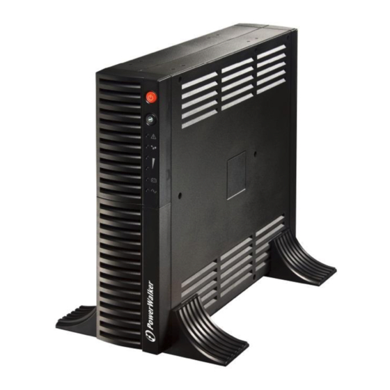
- Page 1 Pure Sine Wave Line Interactive UPS – PowerWalker VI 1000RT/LE PowerWalker VI 1500RT/LE Manual Uninterruptible Power Supply System...
-
Page 3: Safety Instruction - Caution
SAFETY INSTRUCTION – CAUTION 1 IMPORTANT SAFETY INSTRUCTIONS SAVE THESE INSTRUCTIONS - This manual contains important instructions that should be followed during installation and maintenance of the UPS and batteries. – WARNING: Do not attempt to perform repair or service with this UPS. This UPS contains high voltage which could cause electrical shock even when the unit is disconnected from the mains outlet;... - Page 4 8. Do not dispose of battery in a fire. Battery may explode. Proper disposal of battery is required. Please refer to your local laws and regulations for disposal requirements. 9. This UPS contains high voltages which may cause the risk of electric shock. Do not remove cover.
- Page 5 1. INTRODUCTION 1.1 General Introduction This series UPS is pure sine wave line interactive uninterruptible power system with compact design, and it is designed for critical application and environment, such as desktops, servers, workstations, and other networking – equipments. The capacity range is available for 1000VA, and 1500VA. This series protects your sensitive electronic equipments against power problems including power sags, spike, brownouts, line noise, and blackouts.
- Page 6 1.2 Front Panel The UPS front panel indicates the UPS status and also identifies potential power problems. Figure 1 shows the UPS front panel indicators and controls. 1000VA/1500VA Figure 1. Front Panel Description The UPS has a visible indication about the load level in line mode and the battery capacity in Battery mode.
- Page 7 Table 1. LED Indicator Assignment The 5th Green Led Lighting. Optional -- (The 1st to 4th green Led lighting to indicate load level) Line LED1 (green): ≥75% load level. – mode LED2 (green): ≥50% load level. LED3 (green): ≥25% load level. LED4 (green): ≥00% load level.
- Page 8 UPS Rear Panels This section shows the detailed information about the UPS rear panels 1000VA/1500VA Figure 3. Rear Panel Description...
-
Page 9: Installation
2. INSTALLATION 2.1 Inspecting the Equipment If any equipment has been damaged during the shipping process, keep the shipping cartons and packing materials for the carrier or place of purchase – and file a claim for shipping damage. If you discover damage after acceptance, file a claim for concealed damage. - Page 10 Press the button (on the front panel) Connect communication cable from computer to UPS(optional) & Connect equipment to UPS Connect UPS to power Figure 4. Typical UPS Installation 2.3 1000VA/1500VA Setup in Tower or Rack configurations CAUTION The1000VA/1500VA models can be applied to rack configuration (with optional rack mount kits).
- Page 11 – 2) Slide down the UPS vertically and put the UPS stands at the bottom of the tower. Then place the UPS into two stands carefully. 2. Rack-Mount Configuration Setup This UPS can be installed into standard 19” rack. It requires the height of 2U from the rack.
- Page 12 2) Align the mounting ears with screw holes on the side of the UPS and screw together.(Mind the Left and Right plates, fixing as below) 3) Fix the slide to the rack enclosure with screws 4) Insert UPS into the slide assemblies and lock it well in the rack enclosure...
- Page 13 3. Tower Configuration to Rack-Mount Configuration 1) Slide up the UPS vertically and put the UPS out of the stands. Place the UPS on flat area with a soft and clean cushion – 2) Align the mounting bearings with screw holes on the side of the 3) Align the mounting ears with screw holes on the side of the UPS and screw together then Insert UPS into the slide assemblies and lock it in the rack enclosure...
- Page 14 4. Rack-Mount Configuration to Tower Configuration 1) Unscrew the UPS from the Rack enclosure 2) Unscrew the ears and the bearings from the UPS 3) Slide down the UPS vertically and put the UPS stands at the end of the tower. Place the UPS into two stands carefully...
-
Page 15: Operation
3. OPERATION 3.1 Starting Up After the UPS is connected to a power outlet, the UPS enters Standby mode. To turn on the UPS, press down the button. After the UPS is turned on, it – enters Normal mode. The indicator will light indicating that power is available from the UPS output receptacles. -
Page 16: Additional Ups Features
ADDITIONAL UPS FEATURES 4.1 Communication Options The UPS is equipped with a USB and a DB-9 communication port. Either the USB port or the DB-9 communication port may be used to monitor the UPS. 1. USB Port The UPS can communicate with a USB-compliant computer using WinPower Monitoring Software. - Page 17 You can schedule UPS shutdown/start-up and monitor UPS status through PC. Detail instructions please refer to the e-manual in the software. Figure 5. UPS communicates with a computer using WinPower Installation procedure: Check www.powerwalker.com/winpower.html from time to time to get the latest version of monitoring software.
-
Page 18: Battery Replacement
4.3 Network Transient Protector The Network Transient Protector is located on the rear panel and has jacks labeled IN and OUT. Please connect the input connector of the equipment you are protecting to the jack labeled OUT, and connect the network cable to the jack labeled IN. - Page 19 – Pull the battery out (from right side) onto flat area. 5. Disconnect the BLACK battery cable. 6. Reconnect the BLACK battery cable to the new batteries. 7. Slide the new batteries into battery case. 8. Reconnect the battery cable and screw up the battery bracket. 9.
-
Page 20: Specifications
SPECIFICATIONS MODEL PowerWalker VI 1000RT/LE PowerWalker VI 1500RT/LE Capacity VA/W 1000VA/600W 1500VA/870W Input Voltage 220/230/240VAC Acceptable 0-300VAC Voltage Range Nominal 50/60Hz ±5Hz for Normal Mode; >40Hz for Generator Mode Frequency Output Voltage 220/230/240VAC Regulation +/-15% (Max) of nominal voltage (Normal Mode) - Page 21 Fan Fault (Fault) Red LED and LED1 (the first green) Lighting Output Voltage Red LED and LED2 (the 2 green) Lighting low (Fault) Output Voltage Red LED and LED3 (the 3 green) Lighting high (Fault) Output Short Red LED and LED4 (the 4 green) Lighting –...
-
Page 22: Troubleshooting
7. TROUBLE SHOOTING 7.1 Audible Alarm Trouble Shooting: Problem Cause Solution Sounding every 10 The UPS is Check the input voltage seconds on battery Sounding every 0.5 Output Check load level indicator and seconds overload remove some load Sounding every The battery is Save your work and turn off your second... - Page 23 7.3 General Trouble Shooting: Problem Cause Solution The UPS is not on The power cord is not Check the power cord when power connected correctly connection switch is pressed The wall outlet may be Please contact your local faulty qualified electrician –...
Need help?
Do you have a question about the VI 1000RT/LE and is the answer not in the manual?
Questions and answers