
Related Manuals for Factory Cat MINI-MAG SERIES


Summary of Contents for Factory Cat MINI-MAG SERIES
- Page 1 SERVICE MANUAL Version 1.0 R.P.S. Corporation Phone: 1-800-634-4060 P.O. Box 241 Fax: 1-866-632-6961 Racine, Wisconsin...
- Page 3 FOREWORD Factory Cat/Tomcat service manuals are intended for use by professional, qualified technicians. Attempting repairs or service without the appropriate training, tools, and equip- ment could cause injury to you or others and damage to your piece of equipment that may cause it not to operate properly This manual should be kept in a convenient place for easy reference.
- Page 4 CAUTION! To reduce the chance of personal injury and/or property damage, the following instructions must be careful observed: Proper service and repair are important to the safety of the service technician and the safe reliable operation of all cleaning equipment. If part replacement is necessary, the part must be replaced with one of the same part number or with an equivalent part.
-
Page 5: Safety Precautions
SAFETY SAFETY PRECAUTIONS • Hazardous voltage. Shock, Burns or electrocution can result. ALWAYS disconnect the batteries before servicing machine. • Batteries emit hydrogen gases, explosion or fire can result. Keep sparks and open flame away! • Charge unit in a well ventilated area and keep battery compartment open when charging or explosion or fire could result. - Page 6 SAFETY SAFETY MESSAGE Your safety and the safety of others is very important and operating this unit safely is an important responsibility. To help you make informed decisions about safety, we have provided opera- tion procedures and other safety information in this manual. This information informs you of potential hazards that could hurt you or others.
-
Page 7: Table Of Contents
TABLE OF CONTENTS CONTENTS MAINTENANCE MAINTENANCE SCHEDULE ............1-1 LUBRICATION ..................1-1 MACHINE INRODUCTION CONTROLS ................... 2-1 CHASSIS ..................2-2 BODY ..................... 2-3 SQUEEGEE SYSTEM SQUEEGEE SYSTEM COMPONENTS ........3-1 SQUEEGEE SUSPENSION BREAKDOWN ........3-2 TRIANGLE PLATE & TOW BAR ............3-3 SIDEWAYS MOVEMENT .............3-3 UP/DOWN MOVEMENT ...............3-3 ORDERING BLADES ..............3-4... - Page 8 TABLE OF CONTENTS SOLUTION SYSTEM BRUSH DRIVE ................6-1 DISPENSING SOLUTION ............. 6-1 FILTRATION .................. 6-1 TRACTION DRIVE ................ 6-1 SOLUTION SYSTEM ELECTRICAL CIRCUIT ......6-2 BRUSH ASSIST ................6-2 TRACTION DRIVE ................6-2 ADJUSTING SOLUTION FLOW - BRUSH ASSIST ......6-2 ADJUSTING SOLUTION FLOW - TRACTION DRIVE ......6-2 DRAINING SOLUTION TANK ..............6-3 CLEANING SOLUTION FILTER ............6-3 BRUSH DRIVE SYSTEM...
- Page 9 TABLE OF CONTENTS TRACTION DRIVE SYSTEM TRACTION DRIVE ELECTRICAL CIRCUIT ......... 9-1 AXLE ..................... 9-1 DRIVE MOTOR ................9-1 TIRES & WHEELS ................9-1 CHASSIS SYSTEM 10-1 CHASSIS REPLACEMENT ............10-1 TIRES ....................10-1 CASTERS ................... 10-1 BATTERY SAFETY 11-1 DANGER OF EXPLODING BATTERIES ...........
- Page 10 TABLE OF CONTENTS ELECTRICAL SYSTEM 12-1 SWITCHES ................... 12-1 RELAYS ..................12-1 MOTORS ..................12-1 BRUSH DECK MOTORS ..............12-1 VACUUM MOTOR ................12-2 ACTUATORS ................12-2 WIRING ..................12-2 STANDARD CRIMP ON TERMINALS ..........12-2 MOLEX CONNECTORS ..............12-2 CONTROLLER HIGH AMP OUTPUT TERMINALS ......12-3 ANDERSON BATTERY CONNECTORS ..........12-3 COMPUTER CONTROL SYSTEM 13-1...
- Page 11 TABLE OF CONTENTS FLOWCHART DIAGNOSIS ............13-8 ALL MACHINES .................13-8 BATTERY DIAGNOSTICS 1 OF 1 ..........13-8 EMERGENGY STOP DIAGNOSTIC 1 OF 1 .......13-9 RECOVERY SYSTEM DIAGNOSTICS 1 OF 3 ......13-10 RECOVERY SYSTEM DIAGNOSTICS 2 OF 3 ......13-11 RECOVERY SYSTEM DIAGNOSTICS 3 OF 3 ......13-12 SPRAY JET DIAGNOSTICS 1 OF 2 .........13-13 SPRAY JET DIAGNOSTICS 1 OF 2 .........13-14 BRUSH ASSIST MODELS ............
- Page 12 TABLE OF CONTENTS BLANK THIS PAGE WAS INTENTIONALLY LEFT BLANK toc - 1-6 Mini-Mag Service Manual V1.0...
-
Page 13: Maintenance Maintenance Schedule
MAINTENANCE MAINTENANCE MAINTENANCE SCHEDULE ����� �������������������� ����� ������ ������� ������� � �������������������� � ������������������������������ � ����������������������������������� � ������������������������������������������������� � ����������������������������������������������������������� � ���������������������������� � �������������������������������������������� � �������������������������������������� � ������������������������������������������������ � ����������������� � ������������������������������ � ������������������������� ATTENTION! Make sure machine is turned off and the batteries are disconnected before performing any repairs or service on the machine! Your machine is equipped with up to four brush-type electric motors that require periodic inspection to assess wear. - Page 14 MAINTENANCE �� � � � � � � � �� � � � � � �������������������������������� �������������������� �������� � ������ ���� ����� �������� ������������������� ������� �������� ����������� ����������� ����������������� ������� ������� ������� ������� ������� ������� ����������������������������� ��������������������������������� ���������������������������������� ��������������������������������� ��������������������������������������������������������������� ������...
- Page 15 MAINTENANCE �� � � � � � � � �� � � � � � �������������������������������� ��������������������������������� ������� ������ ������� ���������������� ����������������������������� �������������������������� ��������������� ���������������������� ������� ������ ������� ��������������� ����������������������������� ������������������ ���������������������� ��������������������� ��������������������� ����������������������� ����������������� ������� ������ ������� ����������������������� �����������������������������...
- Page 16 MAINTENANCE BLANK THIS PAGE WAS INTENTIONALLY LEFT BLANK Mini-Mag Service Manual V1.0...
-
Page 17: Machine Inroduction
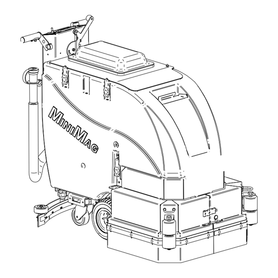
MACHINE INTRODUCTION 1. MAIN POWER SWITCH 2. BATTERY GAUGE 3. SCRUB DECK DOWN PRESSURE GAUGE 4. SPRAY JET SWITCH 5. SCRUB DECK SWITCH 6. KEY SWITCH (OPTIONAL) 7. CIRCUIT BREAKER - 2 AMP 8. CIRCUIT BREAKER - 25 AMP 9. CIRCUIT BREAKER - 40 AMP 10. - Page 18 MACHINE INTRODUCTION 24. TRACTION DRIVE 25. SOLUTION FLOW VALVE 26. SOLUTION FILTER 27. WALL ROLLERS 28. “PAD ASSIST” DRIVE ADJUSTMENT KNOB Mini-Mag Service Manual V1.0...
-
Page 19: Body
MACHINE INTRODUCTION BODY 29. DRIVE BUTTON 30. “DRAIN SAVER” STRAINER 31. VAC SCREEN 32. CASTER 33. MAIN TIRE 34. JAWS 35. TANK IN A TANK 36. SOLUTION FILL ID 37. RECOVERY LID 38. CLEAR COVER 39. CONTROL PANEL 40. SOLUTION LEVEL DRAIN TUBE 41. - Page 20 MACHINE INTRODUCTION 1. MAIN POWER SWITCH: Turns the machine on and off. 2. BATTERY GAUGE: Indicates the amount of battery charge remaining. 3. SCRUB DECK DOWN PRESSURE GAUGE: Indicates the amount of down pressure being applied to scrub deck. 4. SPRAY JET SWITCH (BLUE): Turns spray jet pump on, 5.
- Page 21 MACHINE INTRODUCTION 38. CLEAR COVER: Allows observation inside the recovery tank. 39. CONTROL PANEL: Houses machine controls and electrical components. 40. SOLUTION LEVEL INDICATOR & DRAIN TUBE: Indicates the level of solution in the tank and act as a drain. 41.
- Page 22 MACHINE INTRODUCTION BLANK THIS PAGE WAS INTENTIONALLY LEFT BLANK Mini-Mag Service Manual V1.0...
-
Page 23: Squeegee System
SQUEEGEE SYSTEM SQUEEGEE SYSTEM The MiniMAG’s squeegee system is designed to work with the recovery system to pick up water and dirt from the floor using airflow created by the vacuum motor. The front blade of the squeegee tool is designed with notches that allow the air ,water and dirt to pass through it while metering the air, increasing its speed through the tool and recovery system. -
Page 24: Squeegee Suspension Breakdown
SQUEEGEE SYSTEM A pitch adjustment that allows the operator to adjust the squeegee for different floor surfaces. This is used for creating more of a leak under the front blade for smooth floors or less of one for rough floors. SQUEEGEE SUSPENSION BREAKDOWN �... -
Page 25: Triangle Plate & Tow Bar
SQUEEGEE SYSTEM TRIANGLE PLATE & TOW BAR These parts cannot be bent at all. They must be completely straight and flat. If either is bent replace it. If you replace the triangle plate, adjust the clearance between the bottom of the plate and the top of the tow bar so clearance is 7/8”... -
Page 26: Ordering Blades
SQUEEGEE SYSTEM The front blade wears very well when properly adjusted, but it can get torn. It can be installed one of two ways: “3 notches down” for normal floors, and “5 notches down” for extremely smooth floors. REPLACING BLADES We stock individual blades or blade kits that include a blade set and new set of squeegee wheels. -
Page 27: Squeegee Adjustment
SQUEEGEE SYSTEM SQUEEGEE ADJUSTMENT A squeegee needs to be adjusted to the type of surface that it is operating on. This means the adjustments that pick up well on rough concrete will probably not work well on glass- smooth vinyl tile or ceramic tile. The reverse would hold true also, a squeegee set up for a smooth surface will not work well on rough surfaces. -
Page 28: Squeegee Adjustment Examples
SQUEEGEE SYSTEM SQUEEGEE ADJUSTMENT EXAMPLES ������ � ������ � � � � � � � ���� ������ �������� ������ ���� ��� ��� �������� �������� ��������� ����� ����� ��� ���� �� ��� ������ ���� �� ����� ��� �������� ���� �������� ��� ����� ���� ����� ��� �� �������� ���... - Page 29 SQUEEGEE SYSTEM The squeegee has trailing wheels that MUST touch the floor and roll as the machine is traveling forward. They MUST both be adjusted to the same height. You can check their adjustment by removing the squeegee from the machine, making sure the squeegee has good blades on it and setting the squeegee on a flat surface.
- Page 30 SQUEEGEE SYSTEM ������������������������ ������������������ ����������������� �������������������� �������������������������������������� ������������������������ ���������������������������������������������������������������������������� �������������������������� ����������������������������������������������������������������������������� ������������������������������������� ���������������������������������������������������� ��������������� ������������������������������������ ������������������������������������������������������������ ������������������ ������������������������������������������������������������������������������ ������������������� ����������������������������������������������������������������������������� ����������������������������������������������� �������������������� ���������������������������������� ������������������������������������������������������������������������������� ��������������������������������������������������������������������������������� ����������������������������������� ���������������������������������������������������������������������������� ������������������������������������������������������� �������������������������������������������������������������� ���������������������� ��������������������������������������������������������������������������������� ���������������������� ������������������������������������������� �������������������������������������������������������������������������� �������������������������������������������������� ������������������������������������������������ ������������������������������������������������������� ������������������������������������������������������������������������������� �������������������������������������������������������������������� �������������������������� ���������������������������������������������������������������������������������...
-
Page 31: Squeegee Lift System
SQUEEGEE LIFT SYSTEM SQUEEGEE LIFT SYSTEM The squeegee lift system on the Magnum was designed with simplicity in mind. It has very straight forward operation and minimal parts to assure consistent and highly reliable opera- tion. TO OPERATE Move the squeegee lift lever from right to left. The squeegee will drop and the vacuum motor will then run. -
Page 32: Traction Drive
SQUEEGEE LIFT SYSTEM TRACTION DRIVE Although the squeegee lift is a manual lift there is an electrical circuit that the lift lever is tied to. When the squeegee lever is moved it actuates a switch. This switch send a signal to the controller telling it that the squeegee is down on the floor. -
Page 33: Recovery System
RECOVERY SYSTEM RECOVERY SYSTEM The recovery system of the MiniMag series is powered by a 24 volt 650 watt vacuum motor. The recovery tank is designed with a large lid to facilitate 100% access for complete clean- ing out the recovery tank when use of the machine is finished. The vacuum motor draws air in through the squeegee tool, through the squeegee hose and into recovery tank. -
Page 34: Vacuum Float
RECOVERY SYSTEM VACUUM FLOAT The vacuum float assembly is located inside the RETAINING recovery tank and is accessed by opening the re- CLAMP covery tank lid. The float assembly stops the flow of air to the vacuum motor in the event that the recovery tank is filled to capacity. -
Page 35: Vacuum Motor
RECOVERY SYSTEM VACUUM MOTOR The vacuum motor used on the MiniMAG series scrubbers is a high efficiency, shunt wound motor. The motor runs a approximately 14,300 RPM. The motor is rated at 650 watts and has 72” of water lift. Although the motor has limited service parts available it is advised to replace the entire motor as all the motor parts have about the same life and repairs of the motor unit are usually cost prohibitive. - Page 36 RECOVERY SYSTEM MiniMAG – ALL RECOVERY SYSTEM FLOW CHART 1 of 3 Instruct customer on Machine is not Verify customer Is there a how to operate their picking up water. complaint problem? machine Retest the machine Is the recovery Empty tank and tank empty and the clean ”Drain “Drain Saver”...
- Page 37 RECOVERY SYSTEM MiniMAG – ALL RECOVERY SYSTEM FLOW CHART 2 of 3 FROM PAGE 1 Bill customer Adjust squeegee Instruct customer on and retest proper machine Is the squeegee machine Did this remedy maintenance adjusted properly? (See squeegee the problem? section for assistance) Install squeege...
- Page 38 RECOVERY SYSTEM MiniMAG – ALL RECOVERY SYSTEM FLOW CHART 3 of 3 FROM PAGE 2 Bill the customer Check inside the hose for obstructions Clean out Were any Did this remedy the obstructions or obstructions or problem? clogs and clogs found? retest machine.
-
Page 39: Solution System
SOLUTION SYSTEM SOLUTION SYSTEM The solution system on the MiniMag series consists of main body of the machine which is also the solution tank, the fill opening, sight gauge/drain, filter, potentiometer, controller on traction drive machines or switch on brush drive machines and the solution solenoid valve. BRUSH DRIVE When the solution switch on the central command is switched on the solution is turned on automatically when the brush deck is turned on and turns off automatically when the brush... -
Page 40: Solution System Electrical Circuit
SOLUTION SYSTEM SOLUTION SYSTEM ELECTRICAL CIRCUIT The two types of MiniMAGs have very different solution system circuits. BRUSH ASSIST The electrical circuit of the MiniMAG brush assist series is a very basic design. It consists of the handlebar button, the solution switch, the brush switch and the brush relay. When the brush switch and the solution switch are turned on and the handle bar button is depressed a signal is sent to the brush relay causing it to turn on. -
Page 41: Draining Solution Tank
SOLUTION SYSTEM DRAINING SOLUTION TANK Detach the solution drain / sight gauge hose from the upper barb and lower into a suitable drain or receptacle. When the solution has emptied reattach the hose to the upper barb. SOLUTION DRAIN/ SIGHT GAUGE CLEANING SOLUTION FILTER Drain solution tank with the drain hose. - Page 42 SOLUTION SYSTEM BLANK THIS PAGE WAS INTENTIONALLY LEFT BLANK Magnum Service Manual V1.0...
-
Page 43: Brush Drive System Disc
BRUSH DRIVE SYSTEM BRUSH DRIVE SYSTEM The brush drive system on the MiniMAG Series comes in three versions. The disc type, disc type with brush assist and the cylindrical type. Each one is different although they do the same thing which is turn the scrub brush or scrub pad. DISC The disc brush drive system consists of the controller, 1 or 2 brush drive motors, 1 or 2 brush... -
Page 44: Brush Drive Electrical Circuits
BRUSH DRIVE SYSTEM BRUSH DRIVE ELECTRICAL CIRCUITS BRUSH ASSIST MODELS The negative side of the battery connects directly to the scrub brush motor. The positive side of the battery passes through a relay, from the relay to the 30 amp push button circuit breaker located on the rear of the control panel and then to the scrub brush motor. -
Page 45: Traction Drive Models With Central Command Ii
BRUSH DRIVE SYSTEM TRACTION DRIVE MODELS with CENTRAL COMMAND II The scrub deck pressure is adjusted continuously while scrubbing. Using the brush pressure switch on the control panel you set the desired scrubbing pressure. The de- sired brush pressure is shown on a bar graph on the LCD display. There are 5 different settings to choose from. -
Page 46: Installing & Removing Brushes
BRUSH DRIVE SYSTEM INSTALLING & REMOVING BRUSHES DISC MACHINES With the machine turned on, turn off the brush deck switch. Turn machine power off. Open the two latches on the jaws and swing them aside or loosen the knob and slide the shroud off. -
Page 47: Brush Assist System
BRUSH DRIVE SYSTEM BRUSH ASSIST SYSTEM The brush drive system on the MiniMAG series is also a machine drive assist system. This means that the force created by the pad on the floor is also used to help propel the ma- chine forward when scrubbing. - Page 48 BRUSH DRIVE SYSTEM BLANK THIS PAGE WAS INTENTIONALLY LEFT BLANK Mini-Mag Service Manual V1.0...
-
Page 49: Brush Lift System
BRUSH LIFT SYSTEM BRUSH LIFT SYSTEM The brush lift system for the MiniMag comes in two configurations. The brush assist model uses one system and the traction drive model with Central Command II uses another. BRUSH ASSIST The brush lift system on the brush assist models consists of an actuator, a rocker switch, circuit breaker, lifting linkage and down pressure springs. -
Page 50: Down Pressure Adjustment
BRUSH LIFT SYSTEM DOWN PRESSURE ADJUSTMENT Down pressure is controlled manually by the operator raising or lowering the deck. The amount of down pressure is monitored using the brush pressure gauge located on the lower right corner of the control panel. This gauge should always be in the green when operating. -
Page 51: Traction Drive With Central Command Ii
BRUSH LIFT SYSTEM TRACTION DRIVE WITH CENTRAL COMMAND II The active brush lift system on the MiniMAG series consists of an actuator, down pressure springs, scrub switch and the controller. The brush deck is raised and lowered by the brush deck actuator which is driven by the controller. -
Page 52: Brush Lift System Adjustments
BRUSH LIFT SYSTEM BRUSH LIFT SYSTEM ADJUSTMENTS The brush lift system has two adjustments that can be made. The first adjustment is the length of travel of the actuator ram. This controls how far down it will allow the brush deck to go. -
Page 53: Linkage Adjustment
BRUSH LIFT SYSTEM LINKAGE ADJUSTMENT If the brush deck is out of adjustment and it can not be remedied with the limit switch ad- justment there is a provision for adjusting the linkage. At the top of the brush deck lift linkage there is a bolt that is secured with a jamb nut. - Page 54 BRUSH LIFT SYSTEM BLANK THIS PAGE WAS INTENTIONALLY LEFT BLANK Mini-Mag Service Manual V1.0...
-
Page 55: Traction Drive System
TRACTION DRIVE SYSTEM TRACTION DRIVE SYSTEM The MiniMAG TD series of scrubbers with Central Command II is powered by an and elec- tric transaxle system. The trans-axle is self contained and bolts to the bottom of the frame. The trans-axle is equipped with a 1/2 horsepower motor that transfers power through a shear key into the differential assembly. - Page 56 TRACTION DRIVE SYSTEM BLANK THIS PAGE WAS INTENTIONALLY LEFT BLANK Mini-Mag Service Manual V1.0...
-
Page 57: Chassis System
CHASSIS SYSTEM CHASSIS SYSTEM The chassis system on the Magnum series is built on a heavy duty 7 gauge powder-coated full frame. The frame gives the machine great strength and durability. Everything is fas- tened to the frame using stainless steel hardware allowing for easy servicing should a repair be needed. - Page 58 CHASSIS SYSTEM BLANK THIS PAGE WAS INTENTIONALLY LEFT BLANK 10-2 Mini-Mag Service Manual V1.0...
-
Page 59: Battery Safety
BATTERY SYSTEM BATTERY SAFETY DANGER OF EXPLODING BATTERIES Batteries contain sulfuric acid and produce explosive mixtures of hydrogen and oxygen. Because self-discharge action generates hydrogen gas even when the battery is not in op- eration. Make sure batteries are stored and worked on in a well ventilated area. ALWAYS wear ANSI Z87.1 (U.S. -
Page 60: Handling Battery Acid
BATTERY SYSTEM HANDLING BATTERY ACID Battery acid, or electrolyte, is a solution of sulfuric acid and water that can destroy clothing and burn the skin. Use extreme caution when handling electrolyte and keep an acid neu- tralizing solution - such as baking soda or house hold ammonia mixed with water - readily available. -
Page 61: Combination Terminal
BATTERY SYSTEM STUD TERMINAL The stud terminal is typically used on heavy duty batter- ies. The terminals have a stainless steel threaded stud embedded in them that the connections are made to. COMBINATION TERMINAL The combination terminals come in a few different configurations. -
Page 62: Battery System
BATTERY SYSTEM BATTERY SYSTEM The battery system for the MiniMAG series consists of 2 - 12 volt deep cycle batteries. They are offered in 2 different sizes of lead acid and 1 size of maintenance free AGM bat- teries. The batteries are the power source for all of the working parts of the machine and must be maintained properly to realize optimal run time as well as longevity. -
Page 63: Battery Cables & Terminals
BATTERY SYSTEM BATTERY CABLES & TERMINALS The battery cable connections must remain tight and corrosion free. In the event that the battery cables or terminals become corroded follow accepted battery safety precautions, disassemble and clean the terminals with a baking soda and water solution and a wire brush, making sure not to get any INSIDE the battery. - Page 64 BATTERY SYSTEM The state-of-charge of a lead acid battery can be determined by the specific gravity of the electrolyte (its weight compared to water). The specific gravity can be measured directly with a hydrometer or determined by the stabilizing voltage. A hydrometer is a bulb-type syringe which will extract electrolyte from a cell.
- Page 65 BATTERY SYSTEM When testing with a load tester you are looking for a difference between cells of the batter- ies. All the battery cells should have similar readings. Any battery that contains a cell that has a value lower than .050 of the rest of the cells indicates you have a bad battery. Load test with a load tester: Make sure batteries are fully charged.
-
Page 66: Battery Replacement
BATTERY SYSTEM BATTERY REPLACEMENT When replacing batteries in a machine it is important to replace them with quality batteries that are designed for high-output deep-cycle applications, such as the ones furnished by the factory when the machine was new. All batteries are NOT created equal. In the event you are considering other manufactures batteries make sure to compare their 75 AMP RESERVE CAPACITY. -
Page 67: Electrical System
ELECTRICAL SYSTEM ELECTRICAL SYSTEM The electrical system on the MiniMAG series is a 24 volt system. This is not a chassis ground system thnere is a seperate positive and ground wire that runs to each component. SWITCHES The switches we use all have a similar face but are configured differently internally. Major- ity of them interface directly with the machine controller and carry low voltage signals. -
Page 68: Vacuum Motor
ELECTRICAL SYSTEM VACUUM MOTOR The vacuum motor is a very high speed motor that develops vacuum for the recovery sys- tem. The motors are designed to give a service life of about 500 hours. See the “Recovery System” chapter 5 for more information. ACTUATORS The MiniMAG uses only one actuator. -
Page 69: Controller High Amp Output Terminals
ELECTRICAL SYSTEM REMOVAL TOOL MOLEX MINI-FIT JR. CRIMPING TOOL CONTROLLER HIGH AMP OUTPUT TERMINALS (Brush, Vacuum, Traction) The controller high amp output connectors are crimped with a special crimping tool at the factory. The tool is not practical to use in the field so in the event that a new terminal is needed a wire end kit is available that is field installable. - Page 70 ELECTRICAL SYSTEM PINK #130 ORANGE #71 RED #83 WHITE #131 BLACK #72 BLACK #184 ORANGE #242 ORANGE #243 RED #27 ORANGE #71 ORANGE #71 BLACK #72 BLACK #72 BLACK #72 PINK #130 PINK #130 RED/WHT #250 WHITE #131 WHITE #131 RED #20 RED/WHT #220 GREEN #221...
- Page 71 ELECTRICAL SYSTEM 12-5 Mini-Mag Service Manual V1.0...
- Page 72 ELECTRICAL SYSTEM 10 Ga. RED TO VACUUM MOTOR 10 Ga. RED TO BRUSH MOTOR PINK #130 ORANGE #71 RED #83 WHITE #131 BLACK #72 BLACK #184 ORANGE #71 RED #183 RED #35 RED #35 BLACK #72 WHITE #131 PINK #130 BLUE #135 RED #244 RED #244...
- Page 73 ELECTRICAL SYSTEM 12-7 Mini-Mag Service Manual V1.0...
- Page 74 ELECTRICAL SYSTEM ��������� �������� ����������� ���������� ���� �������������� � ����������������������������������� � ������������������������������ � ����������������������������� � ����������������������������� � ����������������������������� � ����������������������������� � ����������������������������������� � ����������������������������������� � ����������������������������������� �� ��������������� �� ��������������� �� ��������������� �� ��������������� ����� ���������� �� ������ ����������������������� �� �����������������������������...
- Page 75 ELECTRICAL SYSTEM ����� ��������������� �� ������������������������������� �� ���������������������������� �� �������������������������������������������� �� ������������������������������������ �� ������������������������������������������������������������������ �� ��������������������� �� ������������������������������� ������ ������������� �� ������������� �� �������������� �� �������������� �� �������������� �� ������������� �� �������������� �� ���������������������� �� ���������������������� USED ON ONLY 390, 420 and 430 ��...
- Page 76 ELECTRICAL SYSTEM ������� ������������������������������� ��� ������������������� ��� �������������������� ��� ������������������������������������ ��� ��������������������������������������� ��� ������������������� ��� ������� ��������������� ��� ������ ��������������� ��� ���������������������������������������������� ��� ���������������������������� ��� ���������������������������� ������� ����������������� ��� �������������������������� ��� �������������������������� ��� ������������������������� ��� ������������������������� ��� ����������������� ��� ���������������� ���...
- Page 77 ELECTRICAL SYSTEM ������� ������������� ��� ���������������������� ��� ������� ������������� ��� �������� ��� �������� ��� ������ ��� �������������� ��� ������������������ ��� ������ ����������� ��� ������ ����������� ��� ����������������������������� ��� ���������������������������� ��� ��������������������� ��� ������������������� ��� ����������������������� ��� ����������� ��� ���������������������� ��� �����������������������...
- Page 78 ELECTRICAL SYSTEM BLANK THIS PAGE WAS INTENTIONALLY LEFT BLANK 12-12 Mini-Mag Service Manual V1.0...
-
Page 79: Computer Control System
CENTRAL COMMAND CONTROLLER COMPUTER CONTROL SYSTEM The Magnum series of machines is equipped with the Central Command II control system. Central Command II is designed around a very powerful controller that is has a industrial computer integrated into it. The controller is linked to a Liquid Crystal Display (LCD) to relay information to the operator or the service technician. -
Page 80: Soft Start
CENTRAL COMMAND CONTROLLER SOFT START Three of the outputs; traction, brush & vacuum, have a soft start function on them. This function provides the ability to start and stop a motor gradually over a measured period of time, 0-10 seconds. This aids in the longevity of the motors and anything driven by them as it greatly decreases the shock load on them. -
Page 81: Lcd Display
CENTRAL COMMAND CONTROLLER LCD DISPLAY The LCD display is a multi function display that conveys machine information to the opera- tor about the operation state of the machine and diagnostic information in the event of a malfunction. The LCD display communicates to the controller on a serial data connection that is made via the 6 wire connector running from the display to the controller. -
Page 82: Screen 3
CENTRAL COMMAND CONTROLLER SCREEN 3 To access this from screen 1 press the green page button twice. 9: BATTERY METER - This meter shows the charge level of the batteries in the machine. This gauge is designed to read properly while the machine is in use and therefore will vary during usage of the machine. -
Page 83: On Board Diagnostics
CENTRAL COMMAND CONTROLLER ON BOARD DIAGNOSTICS The Central Command II control system utilizes a Diagnostic Code system that displays diagnostic codes on the LCD display should a malfunction of the machine occur. The diag- nostic code can be looked up in the diagnostic code chart and it will assist you in determin- ing the cause of malfunction. -
Page 84: Inputs- Variable Voltage
CENTRAL COMMAND CONTROLLER Decide what device there is a request for and how it should operate the device. TRI-STATE LOGIC The Central Command II system uses very low voltage throughout it’s control system. This voltage is less than battery voltage and the controller will be destroyed if battery volt- age is induced into the control circuits. -
Page 85: Programming
CENTRAL COMMAND CONTROLLER PROGRAMMING We use the same controllers on nearly all of our machines. The controller’s embedded computer needs a set of instructions to operate the machine. The instructions are the program the computer runs and we can modify this program by changing it’s “parameters”. This is what makes it possible to use the same controller in most of our machines but have each one of them react differently. - Page 86 CENTRAL COMMAND CONTROLLER MiniMAG - ALL BATTERY DIAGNOSTIC FLOW CHART 1 of 1 Operate machine BATTERIES are not Instruct owner on and verify the Do the batteries working properly / proper machine customers work properly? Diminished run time. operation complaint. Is the Are the Fill batteries following...
- Page 87 CENTRAL COMMAND CONTROLLER MiniMAG- ALL EMERGENCY STOP DIAGNOSIS 1 of 1 Operate machine Does the Instruct owner on “EMERGENCY STOP and verify the EMERGENCY proper machine SWITCH” does not work. customers STOP work operation complaint. properly? Replace the Can you EMERGENCY STOP depress the E- SWITCH ASSEMBLY...
- Page 88 CENTRAL COMMAND CONTROLLER MiniMAG – ALL RECOVERY SYSTEM FLOW CHART 1 of 3 Instruct customer on Machine is not Verify customer Is there a how to operate their picking up water. complaint problem? machine Retest the machine Is the recovery Empty tank and tank empty and the clean ”Drain...
- Page 89 CENTRAL COMMAND CONTROLLER MiniMAG – ALL RECOVERY SYSTEM FLOW CHART 2 of 3 FROM PAGE 1 Bill customer Adjust squeegee Instruct customer on and retest proper machine Is the squeegee machine Did this remedy maintenance adjusted properly? (See squeegee the problem? section for assistance) Install squeege...
- Page 90 CENTRAL COMMAND CONTROLLER MiniMAG – ALL RECOVERY SYSTEM FLOW CHART 3 of 3 FROM PAGE 2 Bill the customer Check inside the hose for obstructions Clean out Were any Did this remedy the obstructions or obstructions or problem? clogs and clogs found? retest machine.
- Page 91 CENTRAL COMMAND CONTROLLER MiniMAG – ALL SPRAY JET DIAGNOSTICS 1 of 2 Operate machine Is there Instruct owner on Spray Jet does not work and verify the something wrong proper machine properly customers with the Spray operation complaint. Jet? Turn on the Does the Is there Fill solution tank...
- Page 92 CENTRAL COMMAND CONTROLLER MiniMAG – ALL SPRAY JET DIAGNOSTICS 2 of 2 FROM PAGE 1 Call the factory “A” With a voltmeter set to the Was there Was there DC scale measure from battery battery the negative lead to the voltage? voltage? positive battery terminal.
- Page 93 CENTRAL COMMAND CONTROLLER MiniMAG – BRUSH ASSIST BRUSH ASSIST DIAGNOSIS 1 of 1 Is the Test machine / Drive assist is not machine Advise customer on Verify the working correctly operating proper machine operation complaint correctly? Reduce the amount of assist by rotating the Is there too assist knob...
- Page 94 CENTRAL COMMAND CONTROLLER MiniMAG – BRUSH ASSIST BRUSH DECK ACTUATOR FLOW CHART 1 of 2 Test machine / Does the Advise customer on Brush deck does not raise Verify the brush deck raise or proper machine or lower. complaint. lower? operation.
- Page 95 CENTRAL COMMAND CONTROLLER MiniMAG – BRUSH ASSIST BRUSH DECK ACTUATOR FLOW CHART 2 of 2 Find and repair FROM break in wiring. PAGE 1 Disconnect the wires at the actuator. Attach Do they one of your meter leads to each connector on both have good the wire harness side of the machine.
- Page 96 CENTRAL COMMAND CONTROLLER MiniMAG – BRUSH ASSIST BRUSH DRIVE MOTOR FLOW CHART 1 of 2 Is the Advise customer on Scrub brush motor not Test Machine / brush motor proper machine operating properly Verify Complaint operating operation. properly? Is the main power switch Turn on the main Check condition of...
- Page 97 CENTRAL COMMAND CONTROLLER MiniMAG – BRUSH ASSIST BRUSH DRIVE MOTOR FLOW CHART 2 of 2 FROM FROM PAGE 1 PAGE 1 “A” “B” Check for ( + ) battery voltage on Check for ( + ) battery Is there the other load voltage at the green wire ( + ) battery terminal of the...
- Page 98 CENTRAL COMMAND CONTROLLER MiniMAG – BRUSH ASSIST SOLUTION SYSTEM FLOW CHART 1 of 2 Advise customer on Test Machine / Does the machine proper machine NO Solution flow Verify Complaint dispense water? operation Is the water switch Turn on the water turned on? switch Is the ball...
- Page 99 CENTRAL COMMAND CONTROLLER MiniMAG – BRUSH ASSIST SOLUTION SYSTEM FLOW CHART 2 of 2 From Back out all the way and Previous install lock nut. Retest Call the factory Page machine Does the scrub deck See “Brush drive system” Use your meter to turn on when the green Was the screw backed section...
- Page 100 CENTRAL COMMAND CONTROLLER MiniMAG – BRUSH ASSIST VACUUM MOTOR FLOW CHART 1 of 2 Test machine / Does the Advise customer on Vacuum motor will Verify the vacuum motor proper machine not run complaint run? operation Repair the wiring from the batteries to the main power switch.
- Page 101 CENTRAL COMMAND CONTROLLER MiniMAG – BRUSH ASSIST VACUUM MOTOR FLOW CHART 2 of 2 FROM PAGE 1 Verify there is ( + ) Repair wiring battery voltage on one Do you have between the side of the load Is there ( + ) ( + ) battery batteries and the terminals (the large...
- Page 102 CENTRAL COMMAND CONTROLLER MiniMAG – TRACTION DRIVE w/CCII BRUSH DECK ACTUATOR FLOW CHART 1 of 1 Operate machine BRUSH DECK Instruct owner on and verify the Does the actuator ACTUATOR does not proper machine customers work properly? operate properly. operation complaint.
- Page 103 CENTRAL COMMAND CONTROLLER MiniMAG – TRACTION DRIVE w/CCII BRUSH MOTOR /SINGLE - FLOW CHART 1 of 1 Operate machine Does the Instruct owner on SCRUB MOTOR does and verify the motor work proper machine not work. customers properly? operation complaint. With a voltmeter Does set to the DC volt...
- Page 104 CENTRAL COMMAND CONTROLLER MiniMAG – TRACTION DRIVE w/CCII BRUSH MOTOR / DUAL - FLOW CHART 1 of 1 Operate machine Do both Instruct owner on SCRUB MOTOR does and verify the motors work proper machine not work. customers properly? operation complaint.
- Page 105 CENTRAL COMMAND CONTROLLER MiniMAG – TRACTION DRIVE w/CCII BRUSH PRESSURE SWITCH DIAGNOSIS 1 of 2 Operate machine Instruct owner on “BRUSH PRESSURE” and verify the Does the switch proper machine switch does not work. customers work properly? operation complaint. At the 20 pin Molex connector at the controller, back probe Using voltmeter set the meter to pin #16 with the positive probe...
- Page 106 CENTRAL COMMAND CONTROLLER MiniMAG – TRACTION DRIVE w/CCII BRUSH PRESSURE SWITCH DIAGNOSIS 1 of 2 Operate machine Instruct owner on “BRUSH PRESSURE” and verify the Does the switch proper machine switch does not work. customers work properly? operation complaint. At the 20 pin Molex connector at the controller, back probe Using voltmeter set the meter to pin #16 with the positive probe...
- Page 107 CENTRAL COMMAND CONTROLLER MiniMAG – TRACTION DRIVE w/CCII BRUSH PRESSURE SWITCH DIAGNOSIS 2 of 2 FROM FROM PAGE 1 PAGE 1 “A” “B” Place the ( + ) probe back on the center With a voltmeter set to the DC scale terminal of the switch.
- Page 108 CENTRAL COMMAND CONTROLLER MiniMAG – TRACTION DRIVE w/CCII BRUSH SWITCH DIAGNOSIS 1 of 2 Operate machine Instruct owner on “BRUSH SWITCH” and verify the Does the switch proper machine does not work properly. customers work properly? operation complaint. Turn on the scrub deck switch and then drive the machine.
- Page 109 CENTRAL COMMAND CONTROLLER MiniMAG – TRACTION DRIVE w/CCII BRUSH SWITCH DIAGNOSIS 2 of 2 FROM PAGE 1 “A” With a voltmeter set to the DC volt scale measure Is the voltage Did the voltage of the Replace the brush from the negative between 4.8 and 5.2 terminal raise to between 4.8 pressure switch...
- Page 110 CENTRAL COMMAND CONTROLLER MiniMAG – TRACTION DRIVE w/CCII BUSS RELAY DIAGNOSIS 1 of 2 Operate machine Is the (+) Instruct owner on “( + ) BUSS BAR” does and verify the buss bar receiving proper machine not power up. customers battery voltage? operation complaint.
- Page 111 CENTRAL COMMAND CONTROLLER MiniMAG – TRACTION DRIVE w/CCII BUSS RELAY DIAGNOSIS 2 of 2 From From Page 1- Page 2 Is there Repair break in the wiring battery voltage between terminal #86 (black wire) across these and the negative buss bar terminals? Is there Repair connection...
- Page 112 CENTRAL COMMAND CONTROLLER MiniMAG – TRACTION DRIVE w/CCII SOLUTION SOLENOID FLOW CHART 1 of 2 Operate machine Instruct owner on “DELTROL VALVE” does and verify the Does the valve proper machine not work properly. customers work properly? operation complaint. Turn on brush deck switch, set potentiometer to the full on position and scrub.
- Page 113 CENTRAL COMMAND CONTROLLER MiniMAG – TRACTION DRIVE w/CCII SOLUTION SOLENOID FLOW CHART 2 of 2 From Page 1 With a voltmeter set to the DC scale back probe between terminals 7 and the negative buss bar with the Did the icon machine turned on.
- Page 114 CENTRAL COMMAND CONTROLLER MiniMAG – TRACTION DRIVE w/CCII DRIVE MOTOR DIAGNOSTICS 1 of 1 Operate machine Does the Instruct owner on “DRIVE MOTOR” does and verify the drive motor work proper machine not work. customers properly? operation complaint. Does Address machine anything else not turning on first.
- Page 115 CENTRAL COMMAND CONTROLLER MiniMAG – TRACTION DRIVE w/CCII KEY SWITCH DIAGNOSTICS 1 of 1 Operate machine Instruct owner on “KEY SWITCH” does not and verify the Does the switch proper machine work. customers work properly? operation complaint. Using a voltmeter set to DC volts. Connect the ( -) probe of the meter to the ( - ) buss bar.
- Page 116 CENTRAL COMMAND CONTROLLER MiniMAG – TRACTION DRIVE w/CCII LCD DIAGNOSTICS 1 of 1 Operate machine Is there Instruct owner on LCD Window does not and verify the something wrong proper machine operate properly. customers with the display? operation complaint. Replace the display and 6 wire harness with a known Call tech support good or a new display and...
- Page 117 CENTRAL COMMAND CONTROLLER MiniMAG- TRACTION DRIVE w/CCII PAGE SWITCH DIAGNOSIS 1 of 1 Operate machine Instruct owner on “PAGE” switch is and verify the Does the switch proper machine in operative. customers work properly? operation complaint. Unplug the 20 pin connector from the back of the LCD display...
- Page 118 CENTRAL COMMAND CONTROLLER MiniMAG – TRACTION DRIVE w/CCII VACUUM MOTOR FLOW CHART 1 of 1 Operate machine Instruct owner on “VACUUM MOTOR” does and verify the Does the motor proper machine not run. customers work properly? operation complaint. Turn on the vac motor switch and depress foot pedal.
- Page 119 CENTRAL COMMAND CONTROLLER MiniMAG – TRACTION DRIVE w/CCII SOLUTION POTENTIOMETER DIAGNOSIS 1 of 3 Operate machine WATER Can you change Instruct owner on and verify the POTENTIOMETER does water volume with the proper machine customers not change water delivery. Potentiometer? operation complaint.
- Page 120 CENTRAL COMMAND CONTROLLER MiniMAG – TRACTION DRIVE w/CCII SOLUTION POTENTIOMETER DIAGNOSIS 2 of 3 FROM PAGE 1 “A” While it’s disconnected, Was there a measure the voltage at the smooth sweeping orange wire that was voltage from 0 to 5 connected to the center volts? terminal of the potentiometer.
- Page 121 CENTRAL COMMAND CONTROLLER MiniMAG – TRACTION DRIVE w/CCII SOLUTION POTENTIOMETER DIAGNOSIS 3 of 3 FROM PAGE 1 “B” Unscrew the solution screen and make sure Was there a good that water flows solid flow of water out freely out of the of the hose? filter when the bowl and filter are...
Need help?
Do you have a question about the MINI-MAG SERIES and is the answer not in the manual?
Questions and answers