Table of Contents
Advertisement
Quick Links
Advertisement
Table of Contents

Related Manuals for Cotek SR Series


Summary of Contents for Cotek SR Series
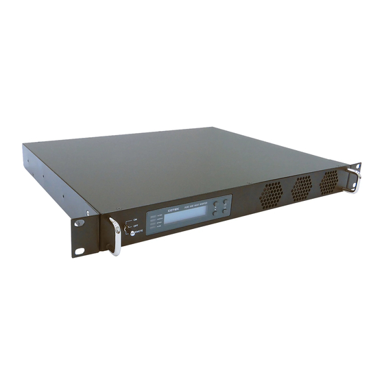
- Page 1 SR Series 1KW Pure Sine Wave Power Inverte User ’s Manual...
-
Page 2: Table Of Contents
SR Series Inverter Contents 1. Important Safety Instructions……………………………………………………………………. 3 1-1 General Safety Precaution…………………………………………………………………… 3 1-2 Other Safety Note………………………...…………………………………………………… 3 2. Introduction to Functional Characteristics……………………………………………………. 4 2-1 System...……………………………………………………………………………………….. 4 2-2 Block Diagram.…………………..……………………………………………………………. 5 2-3 Electrical Performance…..……………………………………………………………………. 6 2-4 Mechanical Drawings..………………………………………………………………………... 7 3. - Page 3 8-1 FCC (Class B) Declaration of Conformity………………………………………………… 8-2 EMC Declaration of Conformity……………….…………………………………………... 8-3 TUV(EN60950) Declaration of Conformity..…………….………………………………... © Copyright: This manual is the copyright of COTEK Electronic Industrial. Co., Ltd. And may not be reproduced or copied without the express permission of the owner.
-
Page 4: Important Safety Instructions
SR Series Inverter 1. Important Safety Instructions WARNING! SAVE THESE INSTRUCTIONS – This manual contains important instructions that should be followed during installation and maintenance of the inverter. 1-1. General Safety Precautions 1-1-1. Do not expose the inverter to rain, snow, spray or dust. -
Page 5: Introduction To Functional Characteristics
SR Series Inverter 1-2-7. Install the inverter in a well-ventilated area. Do not block the front air vents, or the rear air exhausts of the unit. 1-2-8. Wiring: Adequate input power must be supplied to the inverter for proper use; correct wiring sizes must be ensured. -
Page 6: Block Diagram
SR Series Inverter ▌ RS-232 communication. ▌ Dry contact terminal. ▌ Efficiency >90%. (Full linear load at 220VAC Output) ▌ Advanced Protection Features: Input over/under voltage protection. Internal over temperature protection. Input reverse polarity protection (Fuse). Output overload protection. Output short circuit protection AC input short circuit protection: Breaker (6 Amp or 12 Amp) 2-2. -
Page 7: Electrical Performance
SR Series Inverter 2-3. Electrical Performance Electrical Specification Model No. Item SR1000-124 SR1000-148 SR1000-224 SR1000-248 Voltage 24 VDC 48 VDC 24 VDC 48 VDC Input Over-Voltage Protection 30~34 VDC 60 VDC MAX. 30~34 VDC 60 VDC MAX. Input Characteristics Input Under-Voltage Protection... -
Page 8: Mechanical Drawings
SR Series Inverter 2-4. Mechanical Drawings REMOTE SR Series Inverter Ordering Information Model Input Output Voltage Output Voltage Frequency Number Voltage Nominal Range Range SR1000-124 24 VDC 110 VAC 100~120 VAC 47~63 Hz SR1000-224 24 VDC 230 VAC 200~240 VAC... -
Page 9: Installation And Maintenance
SR Series Inverter 3. Installation and Maintenance 3-1. Rear Panel ANEL OUTPUT AC INPUT NEG(-) POS(+) AC INPUT BREAKER Max. 60V 120Vac 120Vac CHASSIS REVERSE POLARITY WARNING: RS-232 10A 47-63Hz 10.3A max. GROUND INV. FAILURE WILL DAMAGE UNIT DC INPUT... - Page 10 SR Series Inverter 3-1-3. AC output socket: 110VAC 230VAC NEMA I.E.C 60320 C13 Wire color Wire length / Socket 120 VAC 230 VAC gauge Line (L) AC Output NEMA I.E.C C13 Neutral (N) Within 16 feet / AWG# 14~16 Line (L) AC Input I.E.C C14...
- Page 11 SR Series Inverter 1). Before installing the inverter, ensure that the main switch “OFF”. 2). Before using the remote function, ensure that the main switch pressed toward “REMOTE”. 3). Ensure that the remote contacts are off. 4). Use 20 ~ 24 #AWG wire to connect the remote control terminals.
- Page 12 SR Series Inverter Dry Contact Terminal Relay COM. Common contact N.C. Normally closed contact N.O. Normally open contact 3-1-7. DC Input Connection: Follow the instructions to connect the battery cables to the DC input terminals of the inverter. The cables should be as short as possible (less than 6 feet / 1.8 meters ideally) so that they can handle the...
- Page 13 SR Series Inverter M8 SCREW PVC WIRE RING (AWG#4 - #6) TERMINAL POSITIVE+ POSITIVE+ PVC WIRE RING (AWG#4 - #6) TERMINAL WARNING! The recommended inline fuse should be installed as close to the battery positive terminal as possible Failure to use a fuse on the “+” cable running Between the inverter and battery may cause damage to the cable / inverter and will void warranty.
-
Page 14: Deutsch Wichtige Sicherheitshinweise
SR Series Inverter 3-2. Wichtige Sicherheitshinweise Modelle: SR1000-224, SR1000-248 Nennwerte: DC Eingangs Spannung / Strom: 18.0 – 34.0 Vdc, 69 A.(für Modell SR1000-224) DC Eingangs Spannung / Strom: 36.0 – 60.0 Vdc, 35 A.(für Modell SR1000-248) AC Eingangs Spannung: 200 – 240 Vac, 50 Hz, 5 A. - Page 15 SR Series Inverter Modell Nummer Leitungs-Diameter [mm] SR1000-124 / 224 5.19 SR1000-148 /248 4.11 Den DC Eingang an eine 24V/48V Batterie oder am eine andere DC Spannungsquelle anschließen. [+] ist positiv, [-] ist negativ. Umgekehrter Anschluss kann zum durchbrennen der internen Sicherung fuhren und kann den Inverter dauerhaft beschädigen.
-
Page 16: Front Panel
SR Series Inverter 16. Vor Gebrauch muss dieses Gerät an einen zuverlässigen Schutzleiter angeschlossen werden. 17. Dieses Gerät ist vorgesehen für Installation in eine Betriebsstätte mit beschränktem Zutritt und der DC Eingangsanschluss muss an die Rückseite des Baugruppenträgers angebracht werden um zu verhindern das es durch qualifiziertes Service-Personal berührt wird. -
Page 17: Maintenance
SR Series Inverter Data pertaining to the DC input voltage, AC output voltage, AC output frequency, AC output current, etc. and system status can be shown sequentially on the LCD display by pressing these buttons. Please refer to chapter 5 for more information. -
Page 18: Protection Features
SR Series Inverter status LED’s will turn “Green”, The LCD Display will display “Vi, Vo, FQ, Io“. THE, inverter will start operating normally. ▌Set the power switch to the “OFF” position. THE, inverter stops and all the lights that are on will, go off. - Page 19 SR Series Inverter Section 5-3-3). ▌INVERTER: Displays DC-AC inverter status. DC-AC Inverter LED Status Power OK Green Power Not Good ▌BYPASS: Displays Bypass relay status. Bypass LED Status AC Output (Load) Orange AC Input From DC-AC inverter (On-line Mode) DC-AC Inverter...
-
Page 20: Startup Sequence And Standby Status
SR Series Inverter menus or to select the value for set up under setting mode. . Function <Page Up>: You can use the “Page Up” button to scroll through the menus. Function <Page Down>: You can use the “Page Down” button to scroll through the menus. -
Page 21: Setup Menu Operation And Instructions
SR Series Inverter POWER SWITCH SR-1000 INVERTER LCD OFF INITIALIATION .. FAILURE ALARM CHECK INVERTER Vi =XX.X Vo=XXX Vi =XX.X Shutdown FQ=XX.X Io =X.X 1Sec Exchange Vi =XX.X Vo=XXX Vi =XX.X Shutdown FQ=XX.X Io =X.X Alert: Undervoltage!! Vi =XX.X Shutdown... - Page 22 SR Series Inverter Vi =XX.X Vo=XXX Main Menu: FQ=XX.X Io =X.X Select Select Menu: Select Menu: Select Menu: Select Menu: User interface I/P Parameter O/P Parameter RST to default Menu: Function 9 10 11 12 13 14 15 Code: Select...
- Page 23 SR Series Inverter Menu Status Buzzer Message Power ON or Push Keypad Alert FAN Fail or UV Alarm or Overload Alarm Shutdown OVP or UVP or OLP or OTP Disable 4). Alert Setup: When alert occurs, the internal Dry Contact Relay will open / close.
- Page 24 SR Series Inverter Model Setting Value Range 24 V 23 VDC ~ 27 VDC 48 V 46 VDC ~ 54 VDC 10). UV Alarm: Sets Under Voltage (UV) alarm. When the input voltage is lower than the set value, the unit will sound “beep” to remind that the unit is going to shutdown.
- Page 25 SR Series Inverter 14). Bypass Relay: The setup is provided in one of the following two ways: On line Mode or Off line Mode (Exacting, Normal, Haphazard). Default= Normal (Off line). Bypass Relay Mode Menu Switching Feature The bypass relay will switch “ON”...
-
Page 26: Rs232 Communication And Operation
SR Series Inverter 15). Overload Alarm: Sets the overload alarm. When the output power is higher than the set value, the unit will sound “beep” to remind that the unit is going to shutdown. At the same time, the internal Dry Contact Relay will open/close (See details in Section 3-1-6). -
Page 27: Interface Command
SR Series Inverter 6-1-3. The RS232 interface of this unit employs ASCII code to implement the asynchronous serial transmission control. The byte structure is START-BIP – 8 BIT DATA-STOP BIT. Baud rate: 1200/2400/4800/9600(See details in Section 5-3-1). 6-1-4. Coupled with PC software application port. Operation is as detailed in Section 6-2. - Page 28 SR Series Inverter 6-3-2. Command format: This unit supports the following command format. There should always be a CR (0DH) and a LF (0AH) appended to the command while sending the command to this unit. 1). Command to switch the Power ON/OFF: Format: Power <value>...
- Page 29 SR Series Inverter <Function Code> Setting Menu <Function Code> Setting Menus LCD Contrast UVP Recovery LCD Auto-off UV Alarm RS232 Baud-rate O/P Voltage Buzzer Setting O/P Frequency Alert Setting Sync Frequency NOT USED Bypass Relay OVP Setting Overload Alarm OVP Recovery...
- Page 30 SR Series Inverter FUNC 3: Buzzer Setting Setting Menu SETT <value> Buzzer (Beep sound) Disable Shutdown Alert Alert , SHDN Buzzer Setting Message Message , SHDN Message , Alert Msg , Alert , SHDN FUNC 4: Alert Setting Setting Menu SETT <value>...
- Page 31 SR Series Inverter FUNC 9: UVP Recovery Setting Menu SETT <value> Model SR1000-124 23~27 SR1000-224 UVP Recovery SR1000-148 46~54 SR1000-248 FUNC 10: UV Alarm Setting Menu SETT <value> Model SR1000-124 19~23 SR1000-224 UV Alert SR1000-148 38~46 SR1000-248 FUNC 11: O/P Voltage Setting Menu SETT <value>...
-
Page 32: Information
Please note that Cotek is only responsible for ensuring our products are operational before delivering. This warranty will be considered void if the unit has been misused, altered, or accidentally damaged. Cotek is not liable for anything that occurs as a result of the user’s fault. - Page 33 SR Series Inverter...
- Page 34 SR Series Inverter...
- Page 35 SR Series Inverter No. 33, Rong Hsin Rd., Pa Teh City, Tao Yuan County, Taiwan Phone:886-3-3661581 FAX:886-3-3676029 E-mail:sales@cotek.com.tw http:// www.cotek.com.tw 2011.04 A0...
Need help?
Do you have a question about the SR Series and is the answer not in the manual?
Questions and answers