Table of Contents
Advertisement
Quick Links
Download this manual
See also:
User Manual
Advertisement
Table of Contents

Related Manuals for Cotek SR series


Summary of Contents for Cotek SR series
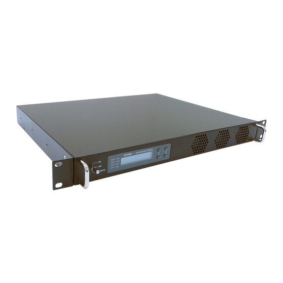
- Page 1 SR Series 1KW Pure Sine Wave Power Inverte User ’s Manual...
-
Page 3: Table Of Contents
Contents 1. Important Safety Instructions……………………………………………………………………. 3 1-1 General Safety Precautions..………………………………………………………………… 3 1-2 Other Safety Notes..……………………...…………………………………………………… 3 Rack-Mounted Installation …………...…………………………………………………..2. Functional Characteristics Introduction ...……………………………………………………. 5 2-1 System...……………………………………………………………………………………….. 2-2 Block Diagram.…………………..……………………………………………………………. 2-3 Electrical Performance…..……………………………………………………………………. 2-4 Mechanical Drawings..………………………………………………………………………... 3. Installation and Maintenance….…………………………………………………………………. 9 3-1 Rear Panel…...…..……………………………………………………………………………. -
Page 4: Troubleshooting
7. Information………………………………………………………………………………………….. 29 7-1 Troubleshooting……………………………………………………………………………….. 29 7-2 Warranty……………………………………………………………………………………..29 Copyright: This manual is the copyright of COTEK Electronic Industrial. Co., Ltd. And may not be reproduced or copied without the express permission of the owner. -
Page 5: Important Safety Instructions
SR Series Inverter 1. Important Safety Instructions WARNING! SAVE THESE INSTRUCTIONS – This manual contains important instructions that should be followed during installation and maintenance of the inverter. 1-1. General Safety Precautions 1-1-1. Do not expose the inverter to rain, snow, spray or dust. -
Page 6: Rack-Mounted Installation
SR Series Inverter 1-2-2. Do not operate near water or in excessive humidity. 1-2-3. Do not open or disassemble the inverter, warranty may be voided. 1-2-4. The DC side connections should be firm and tight. 1-2-5. Grounding: Reliable grounding of rack-mounted equipment should be maintained. -
Page 7: Functional Characteristics Introduction
SR Series Inverter 2. Functional Characteristics Introduction 2-1. System The unit is a highly reliable DC-AC inverter system, designed with advanced power electronic and microprocessor technology offering the following features: The inverter is equipped with a self diagnosis microprocessor that is able to identify and show all failure messages on the LED/LCD display, with associated visual/audio alarms. -
Page 8: Block Diagram
SR Series Inverter RS-232 communication. Dry contact terminal. Efficiency >90%. (Full linear load at 220VAC Output) Advanced Protection Features: Input over/under voltage protection. Internal over temperature protection. Input reverse polarity protection (Fuse). Output overload protection. Output short circuit protection. AC input short circuit protection: Breaker (6 Amp or 12 Amp) 2-2. -
Page 9: Electrical Performance
SR Series Inverter 2-3. Electrical Performance Specification Model No. Electrical SR1000T-124 SR1000T-148 SR1000T-224 SR1000T-248 Item Continuous Output Power 1000W Maximum Output Power 1100W (3 Min) Surge Power 2000W Frequency 47~63Hz ± 0.5% (User-selectable) Output Output Voltage 97~123VAC (User-selectable) 194~246VAC (User-selectable) -
Page 10: Mechanical Drawings
M3*6 39.3[1.55] 39.3[1.55] R3.5[R0.14] PURE SINE WAVE INVERTER AC GRID INVERTER 10.0[0.39] BYPASS REMOTE ALARM 5.9[0.23] 465.0[18.31] 483[19.02] SR Series Inverter Ordering Information Output Voltage Frequency Model Input Output Voltage Voltage Range Range Number Nominal SR1000T-124 24 VDC 110 VAC... -
Page 11: Installation And Maintenance
SR Series Inverter 3. Installation and Maintenance 3-1. Rear Panel ANEL AC OUTPUT AC INPUT AC INPUT BREAKER NEG(-) POS(+) CHASSIS REVERSE POLARITY WARNING: OUTPUT RS-232 GROUND INV. FAILURE WILL DAMAGE UNIT 3-1-1. AC Input Breaker: The AC input circuit breaker protects the unit from overload. When an overload condition occurs, the circuit breaker trips and disconnects the AC grid power input. - Page 12 SR Series Inverter Wire color Wire length / Terminal 120 VAC 230 VAC gauge Line (L) Black Brown AC Output Neutral (N) White Blue Within 16 feet / AWG# 14~16 Line (L) Black Brown AC Input 26~32 feet / Neutral (N)
- Page 13 SR Series Inverter Remote Control Terminal: 1). Before installing the inverter, ensure that the main switch “OFF”. 2). Before using the remote function, ensure that the main switch pressed toward “REMOTE”. 3). Ensure that the remote contacts are off. 4). Use 20 ~ 24 #AWG wire to connect the remote control terminals.
- Page 14 SR Series Inverter Remote Control Terminal: Dry Contact Terminal Relay COM. Common contact N.C. Normally closed contact N.O. Normally open contact 3-1-7. DC Input Connection: Follow the instructions to connect the battery cables to the DC input terminals of the inverter. The cables should be as short as possible (less than 6 feet / 1.8 meters ideally) so that they can handle the required...
- Page 15 SR Series Inverter NEGATIVE- PVC WIRE RING TERMINAL (AWG#4 - #6) PVC WIRE RING TERMINAL POSITIVE+ (AWG#4 - #6) WARNING! The recommended inline fuse should be installed as close to the battery positive terminal as possible Failure to use a fuse on the “+” cable running Between the inverter and battery may cause damage to the cable / inverter and will void warranty.
-
Page 16: Front Panel
SR Series Inverter 3-2. Front Panel RONT ANEL Vi =24.0 Vo=115 FQ=60.0 Io =8.5 REMOTE 3-2-1. Main Switch: These are the 3-stage rocker switches for turning on, turning off and remote mode. 3-2-2. LED’s Indicators: See details in Section 5-1. -
Page 17: Connecting The Loads
SR Series Inverter 4-2. Connecting the loads Calculate the total power consumption(W) of the output load. Make sure that the total power consumption does not exceed the rated load. Should the total load exceed the rated capacity of the inverter, remove the non-critical. - Page 18 SR Series Inverter 5-1-2. LED Indications: AC GRID: Displays AC input status. AC Input LED Status AC input and DC-AC Inverter Green Output are Synchronous AC input ON Orange AC input OFF Note. Synchronous means that the: grid AC input frequency and DC-AC inverter output frequency or phase are the same (See details in Section 5-3-3).
-
Page 19: Startup Sequence And Standby Status
SR Series Inverter Function of Various Keys : Function <Up>: You can use the “up” button to scroll through the menus. or to select the value for set up under setting mode. Function <Down>: You can use the “Down” button to scroll through the menus or to select the value for set up under setting mode. -
Page 20: Setup Menu Operation And Instructions
SR Series Inverter POWER SWITCH SR-1000 INVERTER INITIALIATION .. FAILURE ALARM CHECK INVERTER Vi =XX.X Vo=XXX Vi =XX.X Shutdown FQ=XX.X Io =X.X 1Sec Vi =XX.X Vo=XXX Exchange Vi =XX.X Shutdown FQ=XX.X Io =X.X Alert: Undervoltage!! Vi =XX.X Shutdown Alert: Overload!! Vi =XX.X... - Page 21 SR Series Inverter Vi =XX.X Vo=XXX Main Menu: FQ=XX.X Io =X.X Select Select Menu: Select Menu: Select Menu: Select Menu: User interface I/P Parameter O/P Parameter RST to default Menu: Function 9 10 11 12 13 14 15 Code: Select...
- Page 22 SR Series Inverter Menu Status Buzzer Message Power ON or Push Keypad Alert FAN Fail or UV Alarm or Overload Alarm Shutdown OVP or UVP or OLP or OTP Disable 4). Alert Setup: When alert occurs, the internal Dry Contact Relay will open / close.
- Page 23 SR Series Inverter Model Setting Value Range 24 V 23 VDC ~ 27 VDC 48 V 46 VDC ~ 54 VDC 10). UV Alarm: Sets Under Voltage (UV) alarm. When the input voltage is lower than the set value, the unit will sound “beep” to remind that the unit is going to shutdown.
- Page 24 SR Series Inverter 14). Bypass Relay: The setup is provided in one of the following two ways: On line Mode or Off line Mode (Exacting, Normal, Haphazard). Default= Normal (Off line). Transfer Relay Mode Menu Switching Feature The transfer relay will switch “ON”...
-
Page 25: Rs232 Communication And Operation
SR Series Inverter 15). Overload Alarm: Sets the overload alarm. When the output power is higher than the set value, the unit will sound “beep” to remind that the unit is going to shutdown. At the same time, the internal Dry Contact Relay will open/close (See details in Section 3-1-6). -
Page 26: Interface Commands
SR Series Inverter 6-1-3. The RS232 interface of this unit employs ASCII code to implement the asynchronous serial transmission control. The byte structure is START-BIP – 8 BIT DATA-STOP BIT. Baud rate: 1200/2400/4800/9600(See details in Section 5-3-1). 6-1-4. Coupled with PC software application port. Operation is as detailed in Section 6-2. - Page 27 SR Series Inverter 6-3-2. Command format: This unit supports the following command format. There should always be a CR (0DH) and a LF (0AH) appended to the command while sending the command to this unit. 1). Command to switch the Power ON/OFF: Format: Power <value>...
- Page 28 SR Series Inverter <Function Code> Setting Menu <Function Code> Setting Menus LCD Contrast UVP Recovery LCD Auto-off UV Alarm RS232 Baud-rate O/P Voltage Buzzer Setting O/P Frequency Alert Setting Sync Frequency NOT USED Bypass Relay OVP Setting Overload Alarm OVP Recovery...
- Page 29 SR Series Inverter FUNC 3: Buzzer Setting Setting Menu SETT <value> Buzzer (Beep sound) Disable Shutdown Alert Alert , SHDN Buzzer Setting Message Message , SHDN Message , Alert Msg , Alert , SHDN FUNC 4: Alert Setting Setting Menu SETT <value>...
- Page 30 SR Series Inverter FUNC 9: UVP Recovery Setting Menu SETT <value> Model SR1000T-124 23~27 SR1000T-224 UVP Recovery SR1000T-148 46~54 SR1000T-248 FUNC 10: UV Alarm Setting Menu SETT <value> Model SR1000T-124 19~23 SR1000T-224 UV Alert SR1000T-148 38~46 SR1000T-248 FUNC 11: O/P Voltage Setting Menu SETT <value>...
- Page 31 Please note that Cotek is only responsible for ensuring our products are operational before delivering. This warranty will be considered void if the unit has been misused, altered, or accidentally damaged. Cotek is not liable...
- Page 32 No. 33, Sec. 2, Renhe Rd., Daxi Township, Taoyuan County 33548, Taiwan Phone +886-3-3891999 FAX +886-3-3802333 E-mail sales@cotek.com.tw http // www.cotek.com.tw 2014.11 A1...
Need help?
Do you have a question about the SR series and is the answer not in the manual?
Questions and answers