Akai MPC User Manual
Hide thumbs
Also See for MPC:
- Quick start manual ,
- User manual (373 pages) ,
- Reference manual (136 pages)
Table of Contents
Advertisement
Quick Links
Advertisement
Table of Contents

Subscribe to Our Youtube Channel
Related Manuals for Akai MPC


Summary of Contents for Akai MPC
-
Page 1: User Guide
User Guide English Manual Version 1.5... -
Page 2: Table Of Contents
Step Sequencer ..........................35 Drum Loops and Chop Mode ......................36 Pad Muting and Track Muting ......................38 Sample Recording ........................... 40 Sample Editing ..........................41 Automating Parameters with the Q-Link Knobs ................412 Using MPC as a Plugin ........................42... - Page 3 Operation (Software) ..........................43 General Features ..........................44 Adjusting the Controls ........................44 Program Types ..........................46 File Browser ............................. 55 Mode Tab Section ........................... 58 Transport Section ..........................61 The Grid ............................64 Software Menus ..........................71 Main Mode............................83 Q-Link Section ..........................
- Page 4 Pad Bank Section .......................... 126 Next Sequence Section ......................... 127 Project Information Section ......................128 Sample Record Mode ........................129 Setting Up to Record with MPC Renaissance ................130 Waveform Display ......................... 131 Record Control Section ......................... 132 Project Information Section ......................135...
- Page 5 Sample Edit Mode ..........................136 Waveform Display ......................... 137 Edit Section............................ 138 Pad Section ........................... 140 Settings Section ..........................141 Process Section ..........................142 Project Information Section ......................145 Chop Mode ............................ 145 Song Mode ............................153 Sequence Playlist Section ......................154 Pad Bank Section ..........................
- Page 6 Operation (Plugin) ..........................178 Differences Between the MPC Plugin and Standalone Application ..........178 Appendix ..............................179 Keyboard Shortcuts .......................... 179 Effects and Parameters ........................181 Glossary ............................. 213 Trademarks and Licenses ........................ 218...
-
Page 7: Welcome To The Mpc
MPC Studio offers the most streamlined MPC experience yet. At under one-inch thin, with low-profile controls and a brushed aluminum body, it's made to move. MPC Studio merges real MPC pads, iconic workflow, and the same MPC software used by MPC Renaissance to give you a fully integrated portable production solution. -
Page 8: About This Manual
This manual was written to help you get familiar with the MPC hardware and software. To avoid confusion, the terminology in this manual is based on the MPC parameter names. You will find the various terms explained in the Glossary at the end of this manual. -
Page 9: Important Notes
Installation section for more information. Installation Before installing the MPC software, make sure your computer meets the system requirements described at akaiprompc.com. This applies whether you'll use MPC software as your host software or as a plugin. ® Windows From a DVD: Power on your computer and operating system, and insert the DVD into your DVD drive. - Page 10 Double-click the file to extract it. Double-click the MPC installer icon. This launches a special installation program. Follow the on-screen instructions. Important: After installing the MPC software, you need to unlock the program on your computer. Please refer to Unlocking the MPC Software. ®...
- Page 11 Unlocking the MPC Software Follow these steps to unlock the MPC software before using it. Connect your MPC hardware to a USB port on your computer. If you are using MPC Renaissance, connect it to a power source, too. Power on the MPC hardware.
-
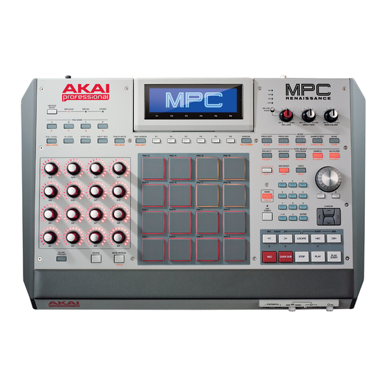
Page 12: Mpc Hardware Overview
MPC Hardware Overview This chapter explains the features and functions of your MPC hardware: the MPC Renaissance or the MPC Studio. MPC Renaissance Top Panel 43 44 11 11 2 2 2 2 2 20 21 22 23 25 26... - Page 13 Navigation and Data Entry Controls Display: This LCD shows all the information relevant to MPC Renaissance's current operation. Much of this information is also shown in the software. Use the Cursor Buttons to navigate through the display, and use the Data Dial, and -/+ buttons to adjust the currently selected setting/parameter.
- Page 14 12. Pad Assign / Pad Copy: Press this button to assign a sample to a pad. In the display, the 4 x 4 grid that appears represents the 16 pads. Use the Cursor Buttons to navigate through the grid, and use the Data Dial or -/+ buttons to select a Program (when the Program field is highlighted) or a sample (when a pad is highlighted).
- Page 15 18. Browser / Save: Press this button to view the File Browser in the display. Hold down Shift and press this button to save the current Project (including its samples, Programs, Sequences, and Songs). 19. Prog Edit / Q-Link: Press this button to enter Program Edit Mode in the display and software. Hold down SHIFT and press this button to assign a parameter to a Q-Link Knob: use the Cursor Buttons to select the desired Q-Link Knob, then use the Data Dial or -/+ buttons to select the desired parameter.
- Page 16 30. Program / Folder 3: Press this button to view only Program files in the File Browser. Hold down Shift and press this button to select the File Browser's Folder 3 shortcut. 31. Sample / Folder 4: Press this button to view only Sample files in the File Browser. Hold down Shift and press this button to select the File Browser's Folder 4 shortcut.
-
Page 17: Front Panel
I/O and Level Controls 43. Mic In / Phono In Switch: Use this switch to select the Mic In or Phono In jacks on the rear panel. If you are using a mic or other line-level audio source connected to the Mic In jacks, select Mic In. If you are using a phono-level device like a turntable connected to the Phono In jacks, select Phono 44. -
Page 18: Rear Panel
Stereo Out: Connect these 1/4" TRS outputs to your speaker system (not included). The signal sent out of these outputs is the main mix. In the MPC software, you can set what is routed to these outputs in the Program Mixer tab, by selecting 1,2 as the Out for one pad or multiple pads. - Page 19 15. MIDI In: Use a five-pin MIDI cable to connect the MIDI Out of an optional external MIDI device to the MIDI In of MPC Renaissance. 16. MIDI Out: Use a five-pin MIDI cable to connect the MIDI Out of MPC Renaissance to the MIDI In of an optional external device.
-
Page 20: Mpc Studio
MPC Studio Top Panel 16 16 16 17 19 29 30 31 24 25 26 27 28 33 34 35 36 37 43 45 44 44 41 42 40 38 39... - Page 21 Power and I/O Computer USB Port: Use the included USB cable to connect this high-retention-force USB port to an available USB port on your computer. This connection allows MPC Studio to send/receive MIDI and audio data to/from the MPC software.
- Page 22 Pad and Q-Link Knob Controls 12. Q-Link Knobs: Use these touch-sensitive knobs to adjust various parameters and settings. The knobs can control one column of parameters at a time. Use the Scroll Knob above them to change which column or row of parameters they currently control. In modes where the display shows a "4 x 4"...
- Page 23 17. Pad Assign / Pad Copy: Press this button to assign a sample to a pad. In the display, the 4 x 4 grid that appears represents the 16 pads. Use the Cursor Buttons to navigate through the grid, and use the Data Dial or -/+ buttons to select a Program (when the Program field is highlighted) or a sample (when a pad is highlighted).
- Page 24 23. Browser / Save: Press this button to view the File Browser in the display. Hold down Shift and press this button to save the current Project (including its samples, Programs, Sequences, and Songs). 24. Prog Edit / Q-Link: Press this button to enter Program Edit Mode in the display and software. Hold down Shift and press this button to assign a parameter to a Q-Link Knob, use the Cursor Buttons to select the desired Q-Link Knob, then use the Data Dial or -/+ buttons to select the desired parameter.
- Page 25 35. Program / Folder 3: Press this button to view only Program files in the File Browser. Hold down Shift and press this button to select the File Browser's Folder 3 shortcut. 36. Sample / Folder 4: Press this button to view only Sample files in the File Browser. Hold down Shift and press this button to select the File Browser's Folder 4 shortcut.
-
Page 26: Quick Start / Tutorial
Quick Start / Tutorial This chapter should help you to familiarize yourself with some basic MPC features. To get the most out of this tutorial, we recommend reproducing each of the described steps. The MPC hardware's display reflects what it is controlling in the software, but due to space and character limitations, the hardware display is slightly different (e.g., parameter names may be abbreviated, the... -
Page 27: Creating A Drum Kit
Creating a Drum Kit Let's start by making a simple drum kit. The Browser display of the MPC hardware Hardware: Press the Browser button and use Cursor Buttons to navigate to where your drum sounds are located: • Use the Up or Down Cursor Buttons to move through a list •... -
Page 28: Recording A Drum Sequence
Recording a Drum Sequence Let's record a drum Sequence. Hardware: Press the Rec button to activate Record Mode. To start the actual recording, press the Play button. The pre-count will count one measure before the software starts to record. We recommend recording only one sound (pad) at a time, especially if you are not familiar with playing on the pads. -
Page 29: Organizing Samples And Editing Note Events
Organizing Samples and Editing Note Events We recommend doing some naming and editing before recording further. Let's use the software, which is easier for editing. The collection of drum samples you loaded earlier (and their respective pad assignments) are arranged in a Program. -
Page 30: Making Basic Sound Edits
Making Basic Sound Edits Let's make sure the samples are properly tuned and have good levels. Hardware: Press the Prog Mix button to enter Program Mixer Mode. Press the F1 button (Level) to control the volume for each pad. You can use the hardware's Q-Link Knobs as well as the corresponding faders in the software. -
Page 31: Recording A Bass Track
Recording a Bass Track Let's try recording a bass line. Unlike a drum kit, it's important to be able to play and record a bass sound chromatically, so this will be slightly different than setting up the drum kit. Adding a bass line over the drum part means we need to add a new Track. A Track is simply a layer of a Sequence;... - Page 32 Tip: On your MPC hardware, press the Pad Bank D button to switch to Pad Bank D and hit Pad 13. You should hear the bass sample played back with its original pitch. You can use the other pads to play your sample chromatically.
- Page 33 You can edit your recording just like we've done earlier. Once you've recorded it, let's tweak it a bit in the Filter section of the Program Edit menu. For this, let's use the MPC hardware. Hardware: Press Prog Edit to enter Program Edit Mode, and press F4 (Flt Env) to enter the Filter page.
-
Page 34: Creating A Song
Creating a Song This section explains how to make a Song out of your Sequences. Before starting, make sure that you have recorded some Sequences (which we described earlier in this chapter)! Click the Song tab to open Song Mode. Each of the Sequences you've created in this Project is assigned to a pad. -
Page 35: Other Features Explained
This chapter describes various advanced features. These sections explain how to perform these operations by using mostly the MPC hardware, but all of them are also possible in the software. For a fuller explanation of these features, please refer to their corresponding sections in the Operation (Software) chapter. -
Page 36: Drum Loops And Chop Mode
Use the Data Dial to select the loaded drum loop. You can scroll through all loaded samples seen the top of your MPC hardware display. Press F1 (Chop) to enter the Chop Mode where the drum loop will be cut into slices. - Page 37 Hardware: Now, let's create a new Program containing all of these slices as individual samples. It will also automatically create corresponding note events to play back these slices sequentially. Press F5 (Convert) to enter the Convert Slices page. Use the Cursor Buttons to navigate to the following parameters and use the Data Dial or -/+ buttons select the value indicated as follows: Convert to Sliced Samples, Crop Samples to On, Create New Program to On, Create Events to On, and Number Of Bars to the bar length of your recorded Track (if you're working with the same one from the earlier tutorial, set it to 2).
-
Page 38: Pad Muting And Track Muting
Pad Mute Mode and Track Mute Mode let you silence different pads and Tracks to see what the Sequence sounds like without those samples or parts. The Pad Mute display of the MPC hardware Hardware: Select your basic drum Track. - Page 39 You can also mute entire Tracks by using the similar Track Mute function. The Track Mute display of the MPC hardware Hardware: Press the Track Mute button to enter Track Mute Mode. Press Play to play the Sequence. Mute a Track by hitting the corresponding pad once. The muted pad will be lit red. You can mute multiple pads at the same time.
-
Page 40: Sample Recording
Sample Recording This section describes recording new samples of your own, which you can use in your Projects. Important: To record any audio, you need to connect an audio source to your MPC Renaissance or to your computer's audio interface. -
Page 41: Sample Editing
Use Q-Link Knobs Q2, Q6, Q10, or Q14, to define a suitable end point for your sample. To hear your edits, press Pad A15 to play the sample from the new start point to the new end point. The Process Sample display of the MPC hardware Let's apply some transformations to the sample. -
Page 42: Automating Parameters With The Q-Link Knobs
Using MPC as a Plugin If you're working with other audio software, you can use the MPC software as an instrument plugin (VST, AU, or RTAS format) within your host software. The MPC plugin offers the same features and functionality as the standalone software version but with some notable differences, which are discussed in the Operation (Plugin) chapter. -
Page 43: Operation (Software)
This chapter explains the complete features and functions of the MPC software. Important: When using the MPC software as a plugin, its features and functions are very similar to how it is described in this chapter but with some notable differences, discussed in the Operation (Plugin) chapter. -
Page 44: General Features
If you hold down your keyboard's Shift key while doing this, you can increase the resolution. The MPC software uses the following types of control elements: Knobs To set a value, click the knob, hold the mouse button, and drag the knob up and down. - Page 45 Switches Switches are represented by "LEDs." If a function is active, its LED will be lit red. To activate a function, click it. Any other LEDs in its set will be automatically deactivated. Buttons Click a button to activate or deactivate its function. Buttons are red when they are activated.
-
Page 46: Program Types
MIDI keyboard or the MPC hardware pads). Two other kinds of Programs use MIDI data only: Plugin Programs and MIDI Programs. This section covers how to create each Program type. To learn about editing your Programs to your preference, see the Program Edit Mode chapter. - Page 47 F6 (Open) to load it. The sample is now "placed" on that pad. The Browser display of the MPC hardware Hardware: Press the Prog Edit button, and then press F1 (Master). With the Q9, Q5, and Q1 Q-Link Knobs, you can assign additional samples to the selected pad.
- Page 48 Keygroup Program To create a Keygroup Program in the software: Click the Main Mode tab to enter Main Mode. In the Track Section, click the Type drop-down menu and select Keygroup. If the Project does not contain a Keygroup Program yet, a new Keygroup Program will automatically be added to the Project.
- Page 49 In the software, click the Program Edit tab. With the Sample drop-down menus for Layer 2 to Layer 4, you can assign up to four samples (loaded into the Project Information beforehand) to create velocity layers or make other layer-dependent adjustments. Hardware: Press the Prog Edit button.
- Page 50 MIDI Program To create a MIDI Program: Click the Main Mode tab to enter Main Mode. In the Track Section, click the Type drop-down menu and select Midi. If the Project does not contain a MIDI Program yet, a new MIDI Program will automatically be added to the Project.
- Page 51 Plugin Program A Plugin Program lets you send your Tracks' MIDI data through a loaded plugin. This lets you route multiple Tracks through the same plugin instead of loading an instance of a plugin on every Track (which can be cumbersome and CPU-intensive).
- Page 52 (Select) to select it or F5 (Back) to cancel. Repeat Steps 2-5 for every Track you want to route to a Plugin. The Edit Program window in the MPC hardware display You can also adjust the volume levels and panning of your Tracks' Plugin Programs. Please see the...
- Page 53 Next, adjust the volume levels and panning of your Tracks' Plugin Programs: In the software, click the Track Mixer icon. Channel strips for the Tracks will be on the left and for the Plugin Programs on the immediate right. Above each channel strip's Pan knob, you will see where its audio is routed.
- Page 54 Important: By default, some plugins do not support MIDI volume and pan. In this case, adjust volume levels and panning on the Track. Track view in Track Mixer Mode in the MPC hardware display Plugin view in Track Mixer Mode in the MPC hardware display...
-
Page 55: File Browser
File Browser The File Browser lets you navigate through your computer's internal and external hard disks to load samples, Sequences, Songs, etc. Using filter buttons and user-definable folders, you can easily adapt the File Browser to your preferred workflow. You can also preview (audition) your samples before loading them. - Page 56 To load a Project, double-click its corresponding .xpj file in the File Browser. To load a single sample or multiple samples into a Project, click and drag the files onto the Pad Bank Section, the grid, or the Project Information section. You can select a single file or multiple files in the following ways: •...
- Page 57 The Browser display of the MPC hardware With the Parent Directory arrow button ( , in the software, to the right of the file path) you can exit the current folder. Hardware: Use the left and right Cursor Buttons to enter or exit a folder.
-
Page 58: Mode Tab Section
Mode Tab Section The Mode Tab Section contains tabs that let you switch between the software modes as well as further control for selecting Programs, Sequences, Songs, etc. depending on the selected mode tab on the left. This section is always visible. The different modes are described in detail in the following sections of this chapter. - Page 59 Depending on the selected mode, some Mode Tab Section menus and functions can change, described here: Click the Program drop-down menu to select one of your Programs in the currently loaded Project. A Project can hold up to 128 Programs. The Program drop-down menu is available only when Program Edit or Program Mixer tab is selected.
- Page 60 Click the Screen Scroll button to switch between Scroll Mode and Page Mode. • Depending on the zoom setting, Scroll Mode will make the screen scroll along in the background, keeping the position marker centered. • Page Mode will make the grid display "turn over" to follow the position marker. Click the View button to switch between Split View and Full-Screen View.
-
Page 61: Transport Section
Tip: If the CPU meter is very high, software response may slow down. Triple-clicking the Stop button (in this Transport Section or on your MPC hardware) will send a "MIDI panic" message. This will halt all messages the software is currently sending, and you can resume normal operation. - Page 62 You can also use the numeric buttons to enter a value and confirm by pressing Enter. Note: The transport controls can be found on the MPC hardware as well as in the software, so the descriptions below apply to both.
- Page 63 MPC Renaissance: Press the Vintage Mode button to switch between the different audio quality emulations. This works only if the MPC Renaissance is set up as the audio output in the Preferences. You can select to emulate the particular sonic qualities of the MPC3000, the MPC60, Other and of course...
-
Page 64: The Grid
The Grid The grid is where you record, program, and edit your Sequences and arrange your Songs. The grid is visible in Main Mode, Program Edit Mode, Program Mixer Mode, Pad Mute Mode, and Step Sequencer Mode. Furthermore, the grid has two different appearances, depending on the selected Program type; Drum Programs appear one way while Keygroup Programs, MIDI Programs, and Plugin Programs appear another way. - Page 65 Command + D (Mac OS X). The selected note events will be automatically copied and pasted, starting from the step just after the last selected note event. When Hitting Pads Select Events is selected, you can hit a pad on your MPC hardware to select all events on that pad in the currently shown Sequence.
- Page 66 Hardware: • Press the Main button and use the Cursor Buttons to navigate to the Trk field. Use the Data Dial or the -/+ buttons to select the desired Track. You can also use the F3 (Track-) or F4 (Track+) buttons.
- Page 67 Grid for Keygroup Programs, MIDI Programs, and Plugin Programs When a Keygroup Progam, MIDI Program, or Plugin Program is selected, the grid looks like this: The only difference from the Drum Program view is the vertical miniature keyboard ("piano roll") in the left grid window section.
- Page 68 Sequence. Press the Stop button when you're finished recording. Tip: Whenever possible, we recommend recording note events with your MPC hardware's pads, which are velocity- and pressure-sensitive, providing a faster and more intuitive recording process.
- Page 69 Command + V (Mac OS X). Tip: Press your MPC hardware's 16 Level button to activate/deactivate 16 Level. When activated, the last pad that was hit will be temporarily copied to all 16 pads. The pads will now output the same note number as the initial pad, but a selectable parameter will be fixed at values that increase as the pad numbers increase (e.g., Pad 1 is the minimum, Pad 16 is the maximum), regardless of how hard you hit them.
- Page 70 Recording/Entering and Editing Automation In the software, follow these steps to record automation data: Tip: Whenever possible, use your MPC hardware (especially the Q-Link Knobs) when recording automation data for faster results. Click the Main Mode tab to enter Main Mode.
-
Page 71: Software Menus
• Use the Select Box Tool (Select Mode) to select several adjacent anchor points for simultaneous editing. • You can add multiple automation parameters using this procedure. Software Menus Some of the software's menu items let you access features that cannot be accessed with the MPC hardware. Important: •... - Page 72 Save Current Sequence saves only the current Sequence. Export lets you export your Project or Sequence data in various formats: MPC formats, a standard MIDI file, a single Project Archive file, or as an audio mixdown file. Select the desired option from the sub- menu.
- Page 73 Exit closes the software. If you have not saved any changes made to a currently open project, it will prompt you to do so before quitting. Mac OS X users: The Exit command is named Quit MPC and located in the MPC menu. Edit Menu Undo undoes the last action you performed.
- Page 74 Delete Unused Samples deletes any samples not assigned to a pad from the Project. Important: The samples will be deleted immediately from the project. The software will not ask for confirmation or allow you to cancel, but you can undo this action (i.e., with the Undo command or hardware button), if needed.
- Page 75 Click the corresponding tab on the left to select it (e.g., MIDI or Sequencer). Click the OK button to close the Preferences window. Preferences will be automatically saved. Mac OS X users: Preferences is located in the MPC menu. • Preferences: Audio Tab...
- Page 76 Hardware: When the MPC hardware is connected and powered on, the available ports as well as the MPC public port are displayed. o Midi Mapping: Click each drop-down menuy to define the Midi Out Port A to D.
- Page 77 Tip: You can "bypass" or ignore the template by opening the MPC software while holding down your computer's Shift key. This will open an empty Project instead of your selected Auto Load file.
- Page 78 Record Pad Aftertouch Events: If this option is enabled, pad aftertouch data (from MPC hardware's pressure-sensitive pads) can be recorded. o Place Events recorded during Count-In at start-point: If this option is enabled, hitting a pad during the recording's pre-count will record that note event at the start of the recording. (This is the MPC3000 worked.)
- Page 79 MIDI Clock or MIDI Time Code (MTC) to the individual ports of the MPC hardware or any connected MIDI interface. Make sure to check the port(s) over which you want to send this information.
- Page 80 Other tab are available through the MPC hardware display. o Tap Tempo: Click this drop-down menu to set how many times you have to press your MPC hardware's Tap Tempo button until the new tempo is recognized. o Filter 'All Notes Off' CC: Check this box to filter out All Notes Off data. If you have connected another device to your MPC hardware's MIDI In, checking this box will cause the software to ignore "All Notes Off"...
- Page 81 Metronome offers the settings for the metronome. • Off disables the metronome. • Play enables the metronome sound during playback only. • Record enables the metronome sound during recording only. • Record + Play enables the metronome to happen in both Record and Playback Modes. Rate lets you to select the metronome click's time division: 1/4, 1/4T, 1/8, 1/8T, 1/16, 1/16T, 1/32 or 1/32T ("T"...
- Page 82 Internet connection to use this function. Set Up MMC Control opens a PDF with instructions on how to allow your MPC hardware's transport buttons to send MMC (MIDI Machine Control) messages from the MPC plugin to your host software. This allows you to use your MPC hardware to control your host software's transport.
-
Page 83: Main Mode
To enter Main Mode, click the Main Mode tab in the Mode Tab Section of the software window. Hardware: Press the Main / Track button. Important: The MPC hardware cannot display as many parameters at the same time as the software. Some of the MPC hardware functions are located on different pages than in the software. - Page 84 Click the Trig drop-down menu and select Min or Max. When you hold down the Q-Link Trigger button on your MPC hardware and touch the top of one the Q-Link Knobs, the corresponding parameters will jump to either its minimum (Min) or maximum (Max) value.
- Page 85 Click the Pad drop-down menu and select the desired pad you want to control. We recommend using Q1 for Pad A01, Q2 for Pad A02 etc., so your controller mapping is easy to remember. Click the Param (Parameter) drop-down menu and select the parameter you want to assign to the Q-Link Knob: o Sample Layer allows you to switch between Sample Layers 1 to 4.
-
Page 86: Pad Bank Section
Click the Trig drop-down menu and select Min or Max. When you hold down the Q-Link Trigger button on your MPC hardware and touch the top of one the Q-Link Knobs, the corresponding parameters will jump to either its minimum (Min) or maximum (Max) value. -
Page 87: Sequence Section
Sequence Section This section gives you an overview of parameters relevant to the current Sequence. In the software, click the Sequence drop-down menu and select a Sequence or click the icon in the lower-right corner of the drop-down menu and select an unused Sequence from the list that appears. Hardware: Move the cursor to Seq and use the Data Dial or the -/+ buttons to select the desired Sequence. -
Page 88: Track Section
Click the Swing field to change the groove of your Sequence. Values range from 50% to 75% and let you "shuffle" your beats—from subtle to extreme. Hardware: Press F1 (T.C) to locate the Swing parameter. It can be changed by using the Data Dial or the -/+ buttons to set the desired value. - Page 89 Click the Type drop-down menu to select what kind of Program the Track will use: a Drum Program, Keygroup Program, Midi Program or a Plugin Program. Track Section for Drum Programs and Keygroup Programs Click the Program drop-down menu to select which Program you want to use. To create a new Program, click the + icon next to the drop-down menu.
- Page 90 127 or to Off. Press F4 (Close) to close the window. The Program Change window in the display of the MPC hardware Track Section for Plugin Programs When the Track's Program Type is set to Plugin, the Track Section will...
- Page 91 Plg field, and then use the Data Dial or -/+ buttons to select the desired plugin. Press F4 (Select) to select it or F5 (Back) to cancel. The Edit Program window in the MPC hardware display Important: Please see Plugin Programs in the Program Types section of this manual to learn how to...
-
Page 92: Project Information Section
Project Information Section The Project Information section shows the Project name as well as all Programs and samples loaded into software's current project. You can simply drag and drop a sample from the Project Information section onto any pad to assign it. How a sample can be played and edited depends Program. - Page 93 Hardware: Press the Window button to open the Edit Current Program display page: • Press F2 (Delete) to delete the selected Program. To avoid accidental deletion, a window opens for you to confirm or cancel the operation. • Press F3 (New) to create a new Program. Use the Data Dial or -/+ buttons to select the type of Program you want to create, and then press F5 (Do It) to confirm or F4 (Cancel) to cancel.
-
Page 94: Program Edit Mode
Important: • MPC Renaissance users: All parameters of Program Edit Mode are arranged in a grid of up to 16 parameters. These parameters correspond to the 16 Q-Link Knobs of the MPC Renaissance. The "4 x 4" grid lets you adjust the parameters shown in MPC Renaissance's display, quickly and intuitively. -
Page 95: Master Section
• In the software, click the pad row in the grid in Program Edit Mode. • On your MPC hardware, hit the desired pad. Master Section In the Master Section, you can set the playback mode and tuning for the overall Program. -
Page 96: Mute Target Section (Drum Programs Only)
Mute Target Section (Drum Programs Only) For the currently selected pad, you can select up to four pads as Mute Targets. When the pad is played, it will immediately silence its Mute Targets. Click each Pad drop-down menu to select the desired Mute Target. -
Page 97: Key Group Section (Keygroup Program Only)
Pad D13. • In a Keygroup Program, you can also use the pads on your MPC hardware to play samples assigned to Keygroups. The 128 pads (A01 to H16) correspond to MIDI notes from from note number 0 to 127, allowing you to easily play a melody with a single sample over a wide range. -
Page 98: Edit Layers Section
Pan controls the overall panning of the loaded sample(s) in the stereo field. Note Range lets you restrict the key range used for a sample's playback. Only notes with a key number higher or equal (Lo) or lower and equal (Hi) to the selected value will trigger a sound. The settings for Lo and Hi are also shown in the virtual keyboard in the Edit Layers section. - Page 99 • On your MPC hardware, press the F3 button and changed the displayed values with the Data Dial or -/+ buttons. A range from 0 to 127 lets the layer respond to the entire velocity range which is input from the respective pad while, for example, a range from 100 to 127 lets the layer respond only to higher velocity levels.
- Page 100 In the software, you can select pads directly in Program Edit Mode by clicking with your computer mouse. On your MPC hardware, you can select pads by striking them.
-
Page 101: Filter Section
Filter Section The Filter Type drop-down menu lets you select a filter for the selected pad. See the Filter definition in the Glossary for an explanation of the available filter types. Cutoff controls the cutoff frequency for low-pass and high-pass filter types or the center frequency for band-pass and band-stop filter types. - Page 102 The Filter Envelope controls affect the filter frequency. The knobs control the envelope shape or time- variant modulation output. Adjust envelope's influence on the filter frequency with the Env knob. See the following Anatomy of an Envelope below to learn about the envelope parameters. The Amp Envelope controls affect level changes over time.
- Page 103 Anatomy of an Envelope An envelope creates a variable control signal. It can be used, for instance, to modulate the filter settings of a sound over a given period of time. For Drum Programs, the software offers two envelope types comprised of separately controllable parameters.
-
Page 104: Pad Play Modes Section (Drum Programs Only)
Pad Play Modes Section (Drum Programs Only) Here, you can set the behavior for each pad's samples in a Drum Program. Mute Groups let you assign the selected pad to one of the 32 available groups. When pads assigned to the same Mute Group receive MIDI notes, the last pad played will silence all other pads in that Mute Group. -
Page 105: Velocity Sensitivity Section
Velocity Sensitivity Section Here, you can set how much velocity affects various sound parameters: Pitch, Filter Envelope Attack (Atk), Amplifier (Amp) and Panning (Pan). When you hit a pad softly, only minimal modulation is applied. When you hit it harder, the modulation amount also gets stronger depending on the setting of the corresponding dial. -
Page 106: Controller Mod Section (Keygroup Program Only)
The LFO modulation Destinations determine the amount of effect of the LFO has on Pitch, Filter Cutoff frequency (Filter), Volume (Amp) and Panning (Pan). Hardware: To edit the LFO parameters, press the F5 button (Lfo Mod). For Drum Programs, use Q-Link Knobs Q1 –... -
Page 107: Pad Insert Effects Section
Pad Insert Effects Section Here, you can select up to four insert effects for each pad. You can use various effects included in your MPC software as well as other VST and AU plugins installed on your computer. Tip: A list of all available MPC software effects and their parameters is in the Effects and Parameters chapter of the Appendix. -
Page 108: Program Edit Mode For Midi Programs And Plugin Programs
Hardware: To edit virtual instrument parameters, press the corresponding F button (Page1 to Page6). Use the MPC hardware Q-Link Knobs for direct access of all 16 parameters that are displayed. You can use the Cursor Buttons to navigate to a desired parameter location in the display and change the... -
Page 109: Program Mixer Mode
Program Mixer Mode In Program Mixer Mode, you can set the levels, stereo panning, and effects for a Program: • For Drum Programs, this mode shows a channel strip for each individual pad (of 128). • For Keygroup Programs, MIDI Programs, or Plugin Programs, this mode shows a channel strip for one channel only. -
Page 110: Routing
16 channels. Use the Data Dial or -/+ buttons to select the desired output. (MPC Renaissance users: Out 1,2 are routed to the Stereo Out jacks. Out 3,4 are routed to the Assignable Mix Out jacks.) Levels In the software, click the channel fader and drag it up or down to set the level. -
Page 111: Panning
Panning In the software, click the channel's Pan knob and drag it up or down to set the position. To view more mixer channels, use the scroll bar under the channel faders at the bottom of the window. Hardware: To set the panning for a channel, press F3 (Pan) and use the corresponding Q-Link Knob for editing. -
Page 112: Insert Effects
Hardware: To load a pad send effect and set its return level: Press Shift + Seq Edit / Effects. Use the Cursor Buttons to select the desired slot. Use the Data Dial or the -/+ buttons to open another page to select an effect. Click F4 (Select) to load it, or click F3 (Back) to close the page. - Page 113 If a loaded project has outputs routed that do not exist on your audio hardware, these will appear in red. Remember: The MPC Renaissance offers the following physical outputs: 1,2 (main out) and 3,4 (assignable).
-
Page 114: Track Mixer Mode
Track Mixer Mode In Track Mixer Mode, you can set the levels, stereo panning, and effects for each Track. In the software, click the Track Mixer tab in the Mode Tab Section. Hardware: To enter Track Mixer Mode, press Shift + Prog Mix / Track Mix. While Program Mixer Mode lets you control the mix of individual pads and sounds within a Program, Track Mixer Mode lets you mix your Tracks within a Sequence. -
Page 115: Routing
Select the output (e.g., Submix 1 or Out 3,4). The software will route the audio signal directly to this selected output. You can select output pairs only if your audio interface supports them. MPC Renaissance: Out 1,2 are routed to the Stereo Out jacks. Out 3,4 are routed to the Assignable Mix Out jacks. - Page 116 Remember: You have to specify where your plugins are located. This can be done in the software's Preferences. See the Preferences: Plugins Tab section for more information. • If your Project already contains the desired plugin, click the Program drop-down menu to select it.
- Page 117 The Edit Program window in the Main Mode section in the display of the MPC hardware The New Program window in the Main Mode section in the display of the MPC hardware From here, you can route Tracks to different plugins by clicking the downward arrow ( ) of the drop-down menu above the Pan knob.
-
Page 118: Levels
Knob for editing. You can use the Pad Bank buttons to select different sets of 16 channels. The Level tab's Track view in the Track Mixer Mode in the display of the MPC hardware The Level tab's Plugin view in the Track Mixer Mode in the display of the MPC hardware... -
Page 119: Panning
Note: MIDI Programs' and Plugin Programs' levels will initially appear as ?. This indicates that the Program is not sending any volume changes, which allows certain plugins to load with their optimal default settings. If you copy a Sequence, the level values will be copied with that Sequence. -
Page 120: Mute And Solo
Mute and Solo In the software, click the channel's Mute button (M). To view more mixer channels, use the scroll bar under the channel faders at the bottom of the window. Hardware: To mute a channel, press F4 (Mute) and press the top of the corresponding Q-Link Knob to toggle between mute and mute off. -
Page 121: Insert Effects
Use the Data Dial or the -/+ buttons to open another page to select an effect. Click F4 (Select) to load it, or click F3 (Back) to close the page. Use the Cursor Buttons to select the effect's Level parameter. Use the Data Dial or -/+ buttons to set the return effect level. -
Page 122: Master Effects
Use the Data Dial or the -/+ buttons to open another page to select an effect. Click F4 (Select) to load it, or click F3 (Back) to close the page. You can repeatedly press F5 (Insert) to cycle through the four available insert effect slots. The small squares below the tab indicate the currently selected slot. -
Page 123: Track View Mode
Track View Mode Track View Mode gives you an overview of the Tracks of each Sequence. Use this mode to edit Tracks and Sequences simultaneously. Tip: Use Track View Mode want to switch quickly between Tracks in a Sequence. This allows for a faster editing workflow. - Page 124 Track View: Drum Program Track View: Keygroup Program...
-
Page 125: Next Sequence Mode
Next Sequence Mode Next Sequence Mode lets you trigger different Sequences simply by playing the pads. This is useful for live performances, letting you change a Song's structure in real time. In the software, click the Next Seq tab in the Mode Tab Section. Hardware: To enter Next Sequence Mode, press the Next Seq button. -
Page 126: Sequence Playlist
Sequence Playlist The Sequence Playlist window in Next Sequence Mode shows a list- style overview of all used Sequences in your Project: • The Sequence column shows the name of the Song's Sequences. • The Length column shows the bar length of a Sequence. •... -
Page 127: Next Sequence Section
Press F3 (Next Bar) to change the Sequence at the beginning of the next bar. This lets you select the next Sequence without having to hit a pad or button in perfect time. The Next Sequence section in the display of the MPC hardware... -
Page 128: Project Information Section
When playback is stopped, this section gives you the following options: • Copy to Song opens a drop-down menu to select a Song the Sequence playlist is copied to. To read more about Song Mode, please see the Song Mode chapter. •... -
Page 129: Sample Record Mode
• the Record Control section (which includes the controls). Important: To record audio, you need to connect an audio source to your MPC Renaissance or to your computer's audio interface. MPC Studio users: This section describes recording using MPC Renaissance as your sound card. MPC Studio cannot be used in this way, but you can use a separate audio interface connected to your computer to record audio. -
Page 130: Setting Up To Record With Mpc Renaissance
"pops" or feedback. Connect your audio source (e.g., a microphone, instrument, etc.) to the Mic In jacks of your MPC Renaissance. If a connected microphone requires phantom power, make sure the Phantom Power switch is set to On. -
Page 131: Waveform Display
Waveform Display The Waveform Display shows the entire waveform of your recorded sample with a timeline at the top. While this is just for reference during in Sample Record Mode, it is the focus of Sample Edit Mode. Please see the Sample Edit Mode section to learn about editing your recorded samples. -
Page 132: Record Control Section
Record Control Section The Record Control section offers all the relevant controls for recording. Threshold In Record Mode, the software automatically starts recording when the level of the incoming source exceeds the Threshold (Thresh). If you set the threshold too high, the recording may not start when you play the input source, or the start of the material you wanted to record may be missing. - Page 133 Data Dial or -/+ buttons to switch it to On. Important: Make sure the Direct Monitoring, Input Monitoring, etc. control of your audio interface or MPC Renaissance is set appropriately so you can hear the incoming signal rather than just the signal from your computer.
- Page 134 • To save the sample, click Keep. To delete the recording and try again, click Retry. To listen to the sample before deciding, click Play. Hardware: When the recording is finished, the MPC hardware's display will show new options. Use the Cursor Buttons to select a field, and use the Data Dial or -/+ buttons to change the setting: •...
-
Page 135: Project Information Section
Project Information Section This section is identical to the Project Information Section in Main Mode. For more information, please see the Project Information Section part of the Main Mode chapter. Newly recorded samples will be shown in the Sample area of Project Information. To use them in your production, you must load them into Programs first. -
Page 136: Sample Edit Mode
Sample Edit Mode Sample Edit Mode lets you edit samples using various functions. In the software, click the Sample Edit tab in the Mode Tab Section. To select a sample to edit, click the Edit Sample drop-down menu in the left section below the waveform display and select a sample from the Project. -
Page 137: Waveform Display
Waveform Display The Waveform Display is divided into two sections: • The top of the display shows an overview of the entire sample waveform. A shaded rectangle outlines the currently shown part of the sample. • The main part of the display shows the "active" section of the sample waveform. Use the scroll bar under the waveform to move through it. -
Page 138: Edit Section
In the main Waveform Display, a start point and end point are marked by green lines. These two points define the portion of the sample data which will be played. Click and drag either of these lines to move it. The most recently moved line will be red instead of green. Tip: A recorded sample may have some silence at the beginning or end, which makes it difficult to time it correctly in a musical context. - Page 139 Hardware: • To adjust the start point of the sample, use Q-Link Knobs Q13, Q9, Q5, or Q1. The smaller the Q- Link Knob number, the more precise the adjustment of the start point. • To adjust the end point of the sample, use Q-Link Knobs Q14, Q10, Q6, or Q2. The smaller the Q- Link Knob number, the more precise the adjustment of the end point.
-
Page 140: Pad Section
Pad Section You can use the pads to play certain parts of the selected sample, regardless of the selected Pad Bank. Trigger the following playback options by hitting the corresponding pad: • Play Loop (Pad 13) plays the sample repeatedly from the loop point to the end point. -
Page 141: Settings Section
Enter. The Sample Edit section in the display of the MPC hardware In the software, you can activate the loop and samples options by clicking the corresponding button: •... -
Page 142: Process Section
Hardware: • Press F4 (Loop) to activate the loop function, which will repeat the part of the sample between the loop point and the end point. • Press F3 (0 Snap) to activate the snap-to-zero function. For easier sample editing, the software will "force"... - Page 143 Data Dial or -/+ buttons to adjust them. To execute a selected option, press F5 (Do It), or cancel your changes by pressing F4 (Cancel). The Process Sample display for Pitch Shift of the MPC hardware The following sample editing options are available: •...
- Page 144 o Log fades the audio in with a logarithmic curve—quickly rising at the start and flattening out towards the end. o Exp fades the audio in with an exponential curve—slowly rising in the beginning and growing steeper towards the end. •...
-
Page 145: Project Information Section
Project Information Section This section is identical to the Project Information Section in Main Mode. For more information, please see the Project Information Section part of the Main Mode chapter. Newly recorded samples will be shown in the Sample area of Project Information. To use them in your production, you must load them into Programs first. - Page 146 Edit Section in Chop Mode In the software: • Use Q-Link Knobs Q13, Q9, Q5, or Q1 to adjust the start point of the sample. The smaller the Q-Link Knob number, the more precise the adjusting of the start point. •...
- Page 147 Pad Section in Chop Mode In Chop Mode you can use the pads to play the sample in the following ways: • Play Loop (Pad 13) plays the sample from the loop point to the end point repeatedly. • Play All (Pad 16) plays the whole sample regardless of any editings.
- Page 148 Use the Cursor Buttons to select a field (Slice, Link, Start, and End). Use the Data Dial or the -/+ buttons to change the value. • Press F4 (Audition) to activate Audition. The Chop Mode display of the Sample edit section in the MPC hardware...
- Page 149 Chop To Section in Chop Mode This section determines the slicing process. You can select between three slicing modes: • Threshold uses an adjustable detection algorithm that derives the number of regions created from the volume levels present in the sample. Click and drag the Threshold field up or down to set the threshold level.
- Page 150 Process Section in Chop Mode This section gives you various editing options for the selected sample. In the software, click the desired sample editing option (described below). A new window will open (which may have some additional parameters). To execute a selected option, click Do It, or cancel your changes by clicking Cancel.
- Page 151 • Sliced Samples creates individual samples from the slices of the current sample. If Crop Samples is activated, each slice results in a new sample. If Create New Program is activated, you will create a new Program in which each slice results in a sample and is automatically assigned to a pad.
- Page 152 Project Information in Chop Mode This section is identical to the Project Information in Trim Mode.
-
Page 153: Song Mode
Song Mode Song Mode lets you arrange Sequences in a specific order and/or repetition to create songs. You can edit the structure of a Song during playback for easy, on-the-fly composing. A Project can contain up to 32 Songs, each consisting of up to 999 "steps," each of which can have an assigned Sequence as well as the number of times that Sequence will repeat. -
Page 154: Sequence Playlist Section
Sequence Playlist Section The Sequence Playlist Section (to the left of the pads in the software) is the list of the steps of a Sequence. Each step in a Song has: • an assigned Sequence • the tempo of the Sequence •... -
Page 155: Pad Bank Section
Pad Bank Section In this section, all Sequences are assigned to a pad. Unused empty Sequences are marked (unused). You can use the Pad Bank buttons to show the Sequences assigned to pads in other banks. You can easily click and drag Sequences from this section and drop them onto the Sequence playlist. -
Page 156: Edit Step
• BPM indicates the Sequence's tempo in beats per minute. Hardware: When a Song is playing, the following buttons are available in the MPC hardware's display: • Sudden switches to the next Sequence before the software has finished playing back the current Sequence. -
Page 157: Project Information Section
Project Information Section This section is identical to the Project Information Section in Main Mode. For more information, please see the Project Information Section part of the Main Mode chapter. -
Page 158: Pad Mute Mode
Pad Mute Mode Pad Mute Mode lets you easily mute pads within a Program or set Mute Groups for each pad. In the software, click the Pad Mute tab in the Mode Tab Section. Hardware: To enter Pad Mute Mode, press Shift + Track Mute / Pad Mute. Pad Mute You can mute or unmute individual sounds (on a single Track) in real time by hitting the pads. - Page 159 Muted pads are lit red; unmuted pads are lit yellow. Unused pads do not show a sample name. The Pad Mute section in the display of the MPC hardware Time Correct lets you quantize Pad Mutes. This is useful when you want your mutes to line up with a specific time division.
-
Page 160: Pad Group
Pad Group The Pad Group feature extends the concept of Pad Mutes: you can mute or unmute multiple pads (on a single Track) by hitting one pad that you have assigned to a Mute Group. This is useful if you want to hear a Track without a particular group of sounds or if you want to isolate specific sounds in various combinations. -
Page 161: Project Information Section
Project Information Section This section is identical to the Project Information Section in Main Mode. For more information, please see the Project Information Section part of the Main Mode chapter. -
Page 162: Track Mute Mode
Track Mute Mode Track Mute Mode lets you easily mute Tracks within a Sequence or set Track Mute Groups to use with the pads. In the software, click the Track Mute tab in the Mode Tab Section. Hardware: To enter Track Mute Mode, press the Track Mute button. -
Page 163: Track Mute Mode
Track. Use the Pad Bank buttons to switch between the 16 banks, if necessary. • Muted pads are lit red; unmuted pads are lit yellow. Unused pads do not show a sample name. The Track Mute section in the display of the MPC hardware... -
Page 164: Track Group Mode
Time Correct lets you quantize Track Mutes. This is useful when you want your mutes to line up with a specific time division. Click the Time Correct drop-down menu and select a value from 1/16th (sixteenth notes) to 2 bar (2 bars). For example, with Time Correct set to 1 bar, your mutes will always align with the beginning of the measure immediately after you press the pad. -
Page 165: Project Information Section
Hardware: Press F2 (TrkGroup) to activate Track Group. Hit a pad to select it. Use the Pad Bank buttons to switch between the 16 banks, if necessary. Use the Data Dial or -/+ buttons to select the desired Mute Group number. •... -
Page 166: Step Sequence Mode
Step Sequence Mode Step Sequence Mode lets you create or edit Sequences by using the pads as "step buttons," simulating the experience of a traditional step-sequencer-style drum machine. In your software, click the Step Seq tab in the Mode Tab Section. Hardware: To enter Step Sequence Mode, press the Step Seq button. -
Page 167: Pad Section
Pad Section This section lets you quickly create and delete note events as "steps" by using the pads of your MPC hardware or MPC software. Tip: Using Step Sequence Mode is most useful for programming drums, emulating the step recording of drums as it was done with various drum machines from the 1980s. - Page 168 Hit an unlit pad to enter a note event at that step. The pad will light up with a color corresponding to its velocity. • Click a lit pad to delete the note event from that step. The pad will be unlit. Working with Step Sequence Mode in the MPC hardware display...
-
Page 169: Midi Control Mode
This custom "control map" will then work whenever you are in MIDI Control Mode. This is useful when using MPC as a plugin: you can use MIDI Control Mode to use your MPC hardware to control your host software, and then switch back to any other mode to control the MPC plugin. - Page 170 To edit a control: Select it by doing one of the following: • clicking it in the software • pressing or moving it on your hardware In the Edit panel on the left side of the software window, set that controls' parameters to your preference.
- Page 171 When you have set all of the parameters as desired, you can select another control or enter another mode. Remember: The edits you make in MIDI Control Mode will be retained with the current MPC Project. If you want to use the same control map for all of your Projects, we recommend saving your control map in your template file.
-
Page 172: Effects
Effects The MPC software offers various effects for processing samples and sound Programs. These same instructions for loading and editing effects are also described in the Program Mixer Mode and Track Mixer Mode chapters, but this section can help you get a good overall understanding of how you can apply these effects. -
Page 173: Pad Effects
If a loaded project has outputs routed that don't exist on your audio hardware, these will appear in red. Remember: The MPC Renaissance offers the following physical outputs: 1,2 (main out) and 3,4 (assignable). - Page 174 Pad Send Effects Important: To use a send effect, you have to load an effect into the corresponding send effect slot in Track Mixer Mode. To load and edit a pad send effect and set its levels: In the software, click the Track Mixer tab in the Mode Tab Section.
-
Page 175: Track Effects
After loading a send effect and setting its return level, set the level the pad sends to it: Enter Program Mixer Mode by pressing the Prog Mix button. Press F4 (Send) to view the pads' channels' send effect levels. (To show another set of 16 pads, use the Pad Bank buttons to select another bank. - Page 176 Track Send Effects Important: To use a send effect, you have to load an effect into the corresponding send effect slot in Track Mixer Mode. To load and edit a Track send effect and set its levels: In the software, click the Track Mixer tab in the Mode Tab Section.
-
Page 177: Master Effects
After loading a send effect and setting its return level, set the level the Track sends to it: Enter Track Mixer Mode by pressing Shift + Prog Mix / Track Mix. Press F4 (Send) to view the channels' send effect levels. (To show another set of 16 channels, select the Track field in the upper-right corner and use the Data Dial or the -/+ buttons. -
Page 178: Operation (Plugin)
Differences Between the MPC Plugin and Standalone Application Saving: Make sure to save your work in the MPC software plugin as well as saving all of your work in your host application. For ease of use, we recommend saving your host application projects and their associated MPC projects in the same folder. -
Page 179: Appendix
Appendix Keyboard Shortcuts You can use the following computer keyboard shortcuts for the MPC software. Cubase users: When running MPC as a plugin in Cubase, all keyboard shortcuts need to be combined with Alt. Control Alt+Control (Windows) (Windows) Function Shift... - Page 180 File Menu Function Control Command (Windows) (Mac OS X) New Project Control + N Command + N New From Template Control + Shift + N Command + Shift + N Control + S Command + S Save Project Control + , Command + , Open Preferences Edit Menu...
-
Page 181: Effects And Parameters
Effects and Parameters This chapter lists the available effects in the software. To learn more about how effects work in the software, please see the Effects chapter. Note: Some of these effects have a "sync" version (e.g., Flanger Sync, Autopan Sync, etc.) whose rates will be affected by the current tempo. - Page 182 Reverb Medium This is a spatial effect, designed to emulate a medium room. Parameter Value Range Default Value Q-Link Knob Number Dry/Wet 0 (dry) – 100 (wet) Pre-Delay 1 – 100 Early Reflection 0 – 100 Density 0 – 100 Diffuse 0 –...
- Page 183 Reverb Large 2 This is a less CPU-intensive spatial effect, emulating the sound of a large hall. Parameter Value Range Default Value Q-Link Knob Number Dry/Wet 0 (dry) – 100 (wet) Pre-Delay 1 – 100 Early Reflection 0 – 100 Density 0 –...
- Page 184 Reverb In Gate This is a hall reverb with an additional control. The reverb effect is cut off when the input drops below the level set in the Gate In parameter. Parameter Value Range Default Value Q-Link Knob Number Dry/Wet 0 (dry) –...
- Page 185 Reverb Out Gate This is a hall reverb that has an additional control. The reverb effect is cut off when the output drops below the level set in the Gate Out parameter. Parameter Value Range Default Value Q-Link Knob Number Dry/Wet 0 (dry) –...
- Page 186 Delays Delays the original signal for a specified period of time and plays it back over an adjustable period of time. Delay Mono Parameter Value Range Default Value Q-Link Knob Number Dry/Wet 0 (dry) – 100 (wet) Time 2 – 2000 ms Feedback 0 –...
- Page 187 Delay Stereo Stereo Delay operates similarly to Mono Delay but in true stereo. Parameter Value Range Default Value Q-Link Knob Number Dry/Wet 0 (dry) – 100 (wet) Time 2 – 2000 ms Feedback 0 – 100 Damping 0 – 100 Delay Sync (Stereo) Stereo Delay operates similarly to Mono Delay but in true stereo.
- Page 188 Delay LP LP Delay is identical to the Mono Delay, but it uses a resonant low-pass filter in the delay line. Parameter Value Range Default Value Q-Link Knob Number Dry/Wet 0 (dry) – 100 (wet) Time 2 – 2000 ms Feedback 0 –...
- Page 189 Delay Analog Analog Delay is similar to Mono Delay, except that it's designed to sound like an analog "Bucket Brigade"- style delay. This delay has a unique character to it that gives a warmer sound by adding subtle inaccuracies in phase and timing. Parameter Value Range Default Value...
- Page 190 Delay Tape Sync Tape Delay emulates a delay system using an analog tape loop and a series of tape heads to produce an echo effect. This delay type yields a very distinct echo sound often heard in reggae and dub-style music. Parameter Value Range Default Value...
- Page 191 Delay Multi-Tap This delay is a mono delay which has three delay generators with independently adjustable delay times and stereo position. Parameter Value Range Default Value Q-Link Knob Number Dry/Wet 0 (dry) – 100 (wet) Time 1 2 – 2000 ms Time 2 2 –...
- Page 192 Flangers A flanger is a modulated delay to emulate the sound created when running two analog tape machines in parallel with a slight time disalignment. Slow Rate settings can produce a "whooshing" jet engine sound, while faster rates result in more of a "warble." Flanger Parameter Value Range...
- Page 193 Chorus A chorus effect uses an LFO to modulate the pitch and a delay of the input signal, which are then added to the dry signal. In small amounts, this creates the illusion of multiple voices playing at once. Turn up the Feedback and Depth for more pronounced "shimmering"...
- Page 194 Autopans This effect uses an LFO to move the incoming signal back and forth across the stereo field, creating a rotary effect. Autopan Parameter Value Range Default Value Q-Link Knob Number Dry/Wet 0 (dry) – 100 (wet) Rate 0 – 100 Autopan Sync Parameter Value Range...
- Page 195 Tremolos This effect uses an LFO to increase and decrease the volume of the signal. Depending on the LFO shape, this can produce a smooth wave effect (sine wave) or a stuttering "on-off" effect (square wave). Tremolo Parameter Value Range Default Value Q-Link Knob Number Dry/Wet...
- Page 196 Phasers The phaser is a classic effect, created by multiple ganged all-pass filters to create "notches," or sharp spikes, in the frequency spectrum. The frequencies of these all-pass filters are usually modulated by an LFO to create a sweeping sound. Phaser 1 Parameter Value Range...
- Page 197 HP Filters HP Filter This effect is a static filter without modulation. Parameter Value Range Default Value Q-Link Knob Number Frequency 10 – 19999 Hz 1500 Resonance 0 – 100 HP Filter Sweep This effect is a high-pass filter with its cutoff frequency modulated by an LFO. Parameter Value Range Default Value...
- Page 198 HP Filter Sync This effect is a high-pass filter with its cutoff frequency modulated by an LFO. Parameter Value Range Default Value Q-Link Knob Number Dry/Wet 0 (dry) – 100 (wet) Low Frequency 0 – 100 High Frequency 0 – 100 Resonance 0 –...
- Page 199 LP Filters LP Filter This effect is a static filter without modulation. Parameter Value Range Default Value Q-Link Knob Number Frequency 10 – 19999 Hz 1500 Resonance 0 – 100 LP Filter Sweep This effect is a low-pass filter with its cutoff frequency modulated by an LFO. Parameter Value Range Default Value...
- Page 200 LP Filter Sync This effect is a low-pass filter with its cutoff frequency modulated by an LFO. Parameter Value Range Default Value Q-Link Knob Number Dry/Wet 0 (dry) – 100 (wet) Low Frequency 0 – 100 High Frequency 0 – 100 Resonance 0 –...
- Page 201 Parametric EQs PEQ 2-Band, 2-Shelf This effect is a combination of one two-band parametric equalizer and two shelving filters. Parameter Value Range Default Value Q-Link Knob Number Low Frequency 22 – 1000 Hz Frequency 1 82 – 3900 Hz Frequency 2 220 –...
- Page 202 PEQ 4-Band This effect is a powerful four-band parametric equalizer with four independent EQ ranges. Parameter Value Range Default Value Q-Link Knob Number Low Frequency 22 – 1000 Hz Frequency 1 82 – 3900 Hz Frequency 2 220 – 10000 Hz 2200 High Frequency 560 –...
- Page 203 Distortions Distortion Amp This effect is designed to reproduce the sound of a tube amplifier at high volumes. Parameter Value Range Default Value Q-Link Knob Number Dry/Wet 0 (dry) – 100 (wet) Drive 0 – 100 Tone 0 – 100 Dynamics 0 –...
- Page 204 Distortion Grimey This is a unique distortion effect that distorts a frequency range in a selectable band. Parameter Value Range Default Value Q-Link Knob Number Dry/Wet 0 (dry) – 100 (wet) Drive 0 – 100 Grime 0 – 100 Center 0 –...
- Page 205 Distortion Custom This effect is a highly customized distortion, capable of a wide range of useable sounds. Parameter Value Range Default Value Q-Link Knob Number Dry/Wet 0 (dry) – 100 (wet) Drive 0 – 100 +Soft 5 – 75 +Clip 5 –...
- Page 206 Compressors A compressor is an effect that changes the dynamic range of a signal by automatically reducing its gain. Compressor Master This is the most transparent compressor, able to perform substantial volume adjustments without artifacts. Parameter Value Range Default Value Q-Link Knob Number Dry/Wet 0 (dry) –...
- Page 207 Compressor Opto The Opto Compressor is modeled after a vintage compressor type using an optical circuit to control the volume reduction of the input signal. These compressors are usually associated with soft and unobtrusive attack and release characteristics. Parameter Value Range Default Value Q-Link Knob Number Dry/Wet...
- Page 208 Compressor VCA This compressor is more modern-sounding, with a slightly more transparent sound. A VCA Compressor tends to have quicker attack and release times than an Opto Compressor. Parameter Value Range Default Value Q-Link Knob Number Dry/Wet 0 (dry) – 100 (wet) Input -6 –...
- Page 209 Compressor Vintage This compressor has a sound similar to classic tube compressors, with their gentle yet pumping response and a dash of tube saturation. Parameter Value Range Default Value Q-Link Knob Number Dry/Wet 0 (dry) – 100 (wet) Input -6 – 18 dB Attack 0 –...
- Page 210 Bit Reducers Decimator Decimator down-samples the incoming signal by removing bits from the digital signal. The difference between decimation and resampling is that Decimator does not use any filtering to mask or correct digital artifacts. The result is an effect ranging from mild to almost completely pure digital distortion, depending on the setting and the source material.
- Page 211 Other Auto Wah This effect is a low-pass filter modulated by an envelope that yields a classic funky "wah-wah"- like sound. The envelope is triggered by the incoming signal's amplitude. The amount of the envelope on the cutoff frequency is user-definable. Parameter Value Range Default Value...
- Page 212 Frequency Shifter A frequency shifter changes the frequencies of an input signal by a fixed amount and alters the relationship of the original harmonics. This can produce a chorus-like effect as well as very crazy artificial timbres. Parameter Value Range Default Value Q-Link Knob Number Dry/Wet...
-
Page 213: Glossary
Glossary A lot of the terms in this manual are based on the MPC parameter names. This glossary briefly explains many of the technical terms used throughout. Aftertouch: The majority of contemporary keyboards are capable of generating aftertouch messages. On this type of keyboard, when you press harder on a key you are already holding down, a MIDI Aftertouch message is generated. - Page 214 Control Change (Controllers): MIDI messages enable you to manipulate the behavior of a sound generator to a significant degree. This message essentially consists of two components: • The controller number, which defines the parameter to be influenced. It can range from 0 to 127. •...
- Page 215 MIDI: MIDI stands for musical instrument digital interface. Developed in the early 1980s, MIDI enables interaction between various types of electronic music instruments from different manufacturers. At the time a communications standard for heterogeneous devices did not exist, so MIDI was a significant advance.
- Page 216 Program: A Program is a file that contains a list of all samples to be used, and settings for each sample (e.g., pad assignments, loop points, pitch tuning, effects, etc.) MPC's Program Edit Mode is where you can edit and assign samples. The software can have a total of 128 Programs in a Project.
- Page 217 Sample: When you tap the pads on your MPC hardware, you can trigger sounds that we call samples. Samples are digitized snippets of audio that can either be recorded using the recording function of your MPC software or loaded from the File Browser.
-
Page 218: Trademarks And Licenses
Trademarks and Licenses Akai Professional and MPC are trademarks of inMusic Brands, Inc., registered in the U.S. and other countries. ASIO, Cubase, and VST are trademarks of Steinberg Media Technologies GmbH. Mac and OS X are trademarks of Apple Inc., registered in the U.S. and other countries. - Page 219 akaiprompc.com...
Need help?
Do you have a question about the MPC and is the answer not in the manual?
Questions and answers