Akai MPC Service Manual
Hide thumbs
Also See for MPC:
- Quick start manual ,
- User manual (373 pages) ,
- Reference manual (136 pages)
Advertisement
Quick Links
SERVICE MANUAL
HARDWARE
Display
Display
Display
Display
Dimensions
Dimensions
Dimensions
Dimensions
Weight
Weight
Weight
Weight
Power Supply
Power Supply
Power Supply
Power Supply
Power Requirement
Power Requirement
Power Requirement
Power Requirement
AUDIO & MIDI I/O
Sample Rates
Sample Rates
Sample Rates
Sample Rates
Monitoring
Monitoring
Monitoring
Monitoring
Record input (L & R)
Record input (L & R)
Record input (L & R)
Record input (L & R)
Max. Input level
Max. Input level
Max. Input level
Max. Input level
Digital Input
Digital Input
Digital Input
Digital Input
4 Audio Outputs
4 Audio Outputs
4 Audio Outputs
4 Audio Outputs
Max. output level
Max. output level
Max. output level
Max. output level
Phones
Phones output
output
Phones
Phones
output
output
Digital output
Digital output
Digital output
Digital output
MIDI inputs
MIDI inputs
MIDI inputs
MIDI inputs
MIDI outputs
MIDI outputs
MIDI outputs
MIDI outputs
USB
USB
USB
USB
F F F F o o o o o o o o t t t t s s s s w w w w i i i i t t t t c c c c h h h h e e e e s s s s
SPECIFICATIONS
360 x 96 dot graphic LCD w/backlight
19.75" x 12.9" x 2.75" (4.9" at max display angle)
502 mm x 328 mm x 70 mm (124 mm at max display angle)
10.5 lbs. / 4.8 kg
External, 12VDC, 2A, center pin positive
24 W max
Up to 24-bit, 96 kHz
Zero-latency hardware monitoring via adjustment knob
XLR/ 1/4" combo x 2 (balanced -40 dBu; input impedance 11 kΩ)
RCA stereo (with phono preamp)
+10 dBu
24-bit RCA-pin x 1 S/PDIF
1/4" phone x 4 (balanced +11 dBu, output impedance 1 kΩ)
+18 dBu
1/4" stereo phone x 1 (200 mW / 100 Ω)
1/8-inch stereo phone x 1 (200 mW / 100 Ω)
24-bit RCA-pin x 1 S/PDIF
5-pin DIN x 2
5-pin DIN x 4
USB 2.0 to computer x 1, plus 2-port, powered USB hub
1/4" x 2
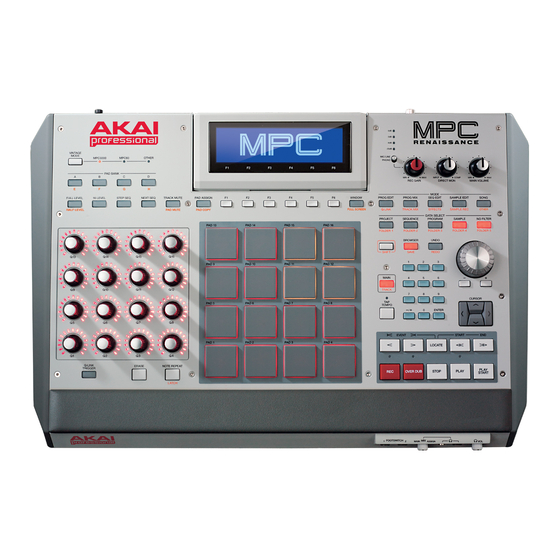
MODEL: MPC
Advertisement

Related Manuals for Akai MPC


Summary of Contents for Akai MPC
- Page 1 SERVICE MANUAL MODEL: MPC SPECIFICATIONS HARDWARE 360 x 96 dot graphic LCD w/backlight Display Display Display Display 19.75" x 12.9" x 2.75" (4.9" at max display angle) Dimensions Dimensions Dimensions Dimensions 502 mm x 328 mm x 70 mm (124 mm at max display angle) 10.5 lbs.
-
Page 2: Disassembly Procedures
DISASSEMBLY PROCEDURES DISASSEMBLE THE BOTTOM CHASSIS. (A)REMOVE 23 SCREWS FROM THE BOTTOM CHASSIS. (B)REMOVE 4 SCREWS FROM THE TOP PANEL. (Fig1) DISASSEMBLE THE REAR PCB ASS’Y. (A)REMOVE 3 SCREWS FROM THE REAR DIGITAL PCB ASS’Y. (B)REMOVE 5 SCREWS FROM THE REAR ANALOG PCB ASS’Y. (C) REMOVE 5 SCREWS FROM THE REAR ANALOG PCB ASS’Y. - Page 3 DISASSEMBLE THE HEADPHONE PCB ASS’Y. (A)REMOVE 2 SCREWS FROM THE HEADPHONE PCB ASS’Y. (Fig3) DISASSEMBLE THE TOP PCB ASS’Y. (A) REMOVE 19 PCS KNOBS AND 1 PC JOG WHEEL FROM THE SUBCHASSIS. (B) REMOVE 8 SCREWS FROM THE PAD HOLDER. (C) REMOVE PAD HOLDER FROM THE TOP PCB ASS’Y.
- Page 4 DISASSEMBLE THE LCM MODULE. (A) REMOVE 4 SCREWS FROM THE SUBCHASSIS. (B) REMOVE 6 SCREWS FROM THE LDM BOTTOM. (Fig5)
-
Page 5: Wiring Diagram
WIRING DIAGRAM (US/EU/UK/JIS/AUS NZ) -
Page 6: Packing Diagram
PACKING DIAGRAM (US/EU/UK/JIS/AUS NZ) -
Page 7: Explode Diagram
EXPLODE DIAGRAM (US/EU/UK/JIS/AUS NZ) - Page 8 EXPLODE DIAGRAM (US/EU/UK/JIS/AUS NZ) EQUENCIAL NO EXPLODE DIAGRAM WILL BE MARKED ON REF.COLUMM OF BOM LIST...
- Page 9 ACV0AKA01 DESCRIPTION LEVEL 0 ACV0AKA01 ACV0 100-240V USA 1 AA821801X Shield LCD(2) 1 AL7-10-1215 Switching ADAPTOR(UL/JIS) DC12V/2A 1 BACR-0012 Foot 1 BACTHG436-1B Hinge 1 BAGL-40A Clip 1 BART-K00702 VR Knob 1 BAW-1136 Washer(Teflon) 1 CA040218004 USB 2.0 1.8M A/B Black CORE 1 CN0100000506 Flat Cable GND Wire Black φ3.2 Length 50mm Line/Female...
- Page 10 1 PT1110685 Button Medium 1 PT1304315 Power Cable Retainer 1 PT150430702 LED Master Ring 1 PT1504309 LED Lens 1 PT1504311 Lamp Guide(1PCS) 1 PT1504425 PAD Holder 1 PT1504426 Fit Washer 1 PT1510610201 Big buttom(8) 2 PT15106102 Big button(8) 1 PT1510610301 Big button(2) 2 PT15106103 Big button(2)
- Page 11 1 TWPT15300200102 LCM module 2 AA821801X Shield LCD(2) 2 EVA1504428 Sponge 2 PT150140801 LCD LENS 3 PT1501408 LCD Lens 2 PT153002002 LCD Panel 3 PT1530020 LCD Panel 2 PT153030703 LCD Bottom 3 PT1530307 LCD Bottom 2 SC2608PBNI Screw M2.6*8 PPN Tapping 1 WR112820032W1 Isolation Cable 12P 200MM PITCH 2MM 1 WS114009605IN...
- Page 12 D374,402~416 3 EC10616TS Capacitor Electrolytic 10uF/16V 4*5mm C19,20 3 EC22616TS Capacitor Electrolytic 22uF/16V 5*5mm C4,5 3 EC47616TS Capacitor Electrolytic 47uF/16V 5*5mm 12 C97,120,125~128,132,133,137,139,170,172 FCN Down Touch ZIF SMD Pitch=1.0mm FCN1T1002602 3 FCN2R1001001 FCN Dual Touch SMD Pitch=1.0mm 10P 3 IC74HC253DR IC 74HC253DR SOIC-16 U12,15 3 IC74HC595...
- Page 13 3 RS024910F03 RES 249 1% SMD 0603 R298 3 RS027010F03 RES 270 1% SMD 0603 16 R48,65,88,99,108,114,116,118,128,130,132 R134,144,146,148,150 3 RS036K10F03 RES 36K 1% SMD 0603 3 RS047010F03 RES 470 1% SMD 0603 R237,249,283,293 3 RS047K10F03 RES 47K 1% SMD 0603 R4,16,41 3 RS04K708F05 RES 4.7K 1% SMD 0805...
- Page 14 2 AL2-54-6306 Mosfet FDC6306P P-CH SSOT-6 Q18,U8 2 AL2-71-0074 IC TL074 QUAD OPAMP SOP-14 2 AL2-71-0163 IC OP-AMP SINGLE INA163 SOP-14 U5,6 2 AL2-71-3079 IC MC33079 QUAD OP-AMP SOP-14 U2,11,12 2 AL4-00-0002 MIDI Jack 8P 90° Female J1,6,11,14,15,16 2 AL4-05-0028 JACK XLR 3-PIN FEM STEREO-COMBO J2,4 PCB/PANEL-MNT 90°...
- Page 15 2 RS010K10F03 RES 10K 1% SMD 0603 12 R30,31,40,48,91,93,103,136,167,260,262,263 2 RS015K10F03 RES 15K 1% SMD 0603 R13~17,34~36 2 RS01K310F03 RES 1.3K 1% SMD 0603 12 R42,68,85,89,96,118,122,129,130,141,142,147 2 RS01K408F05 RES 1.4K 1% SMD 0805 R70,73,79,82,120,135 2 RS022008F05 RES 220 1% SMD 0805 R71,72,74,80,81,83,84,90 2 RS022010F03 RES 220 1% SMD 0603...
- Page 16 C31,32 2 CS180J5003NPO CCAP SMD 18pF/50V 5% 0603 NPO C46,47 2 CS220J5003NPO CCAP SMD 22pF/50V 5% 0603 NPO 2 CS225K1605X7R CCAP SMD 2.2uF/16V 10% 0805 X7R C93~95,98,101,102 2 CS330J5003NPO CCAP SMD 33pF/50V 5% 0603 NPO C52,70,110~114 2 CS333K2502X7R CCAP SMD 0.033UF/25V 10% 0402 X7R C67,71,72,75~77 2 CS471J5003NPO CCAP SMD 470pF/50V 5% 0603 NPO...
- Page 17 R95~98,114 R8,10,12,19,22,112 2 RS010K10F03 RES 10K 1% SMD 0603 2 RS015K10F03 RES 15K 1% SMD 0603 R46,50,51,122 2 RS01K110F03 RES 1.1K 1% SMD 0603 R36,80 2 RS01K310F03 RES 1.3K 1% SMD 0603 2 RS030010F03 RES 300 1% SMD 0603 2 RS033208F05 RES 332 1% SMD 0805 R90,113 2 RS047K10F03...
- Page 18 R372,374 2 RS010K10F03 RES 10K 1% SMD 0603 R263,264 2 RS01K408F05 RES 1.4K 1% SMD 0805 R214,215 2 RS2K8710F03 RES 2.87K 1% SMD 0603 Q90,91 2 TR2SD2114KSM Transistor 2SD2114K NPN SOT-23 R292 2 VRR10301523 Potentiometer Rotary 10K15A Shaft Length 15mm Dual-Unit R291 2 VRR10401504 Potentiometer Rotary 100K3B Shaft Length...
- Page 19 ACV0 Performance Testing Instructions Shane Hazleton 6/18/2012 Ver 8 Overview The ACV0 performance test is done with the ACV0 Tester application which checks the quality of Midi I/O, audio quality, and can be used to serialize a unit. Required Hardware/Software ACV0 with latest FW MPC5000 or IO26 ACV0 USB Audio Driver installed –...
- Page 20 Navigate to the dspControl window in the bottom right and configure the settings to look like this, You don’t need to match everything. The important fields are selecting the correct audio driver and sample rate, which should be done automatically. Midi Tests Knob/Button /LED Tests Turn all knobs their full range up and down.
- Page 21 PAD Bank Butons, TRACK MUTE, MODE Buttons, MAIN Pads Press the pads all the way until the aftertouch value (in top left of app) reaches 127 to pass LED Visual Test Enabling LEDs ON will cause all the LEDs to light with the exception of the INPUT METER LEDs which are analogue and will be checked during the AUDIO TEST.
- Page 22 in the USB HUB ports. Hit TEST USB HUB and the app will see if these files exist on the drives and generate a pass if two drives are found with these files. 5 Pin MIDI Plug 1 MIDI cable from Out A to IN 1 and the other from Out B to IN 2. Hit Test 5 Pin MIDI Group 1.
- Page 23 First connect some speakers or headphones to one of the headphone outs. You will use this to monitor. You should have Windows set to use the MPC as the audio driver too so you can hear the USB device connected “ding”...
- Page 24 DIRECT MON and MAIN VOL are all the way up, maxed. Calibration The user may need to calibrate the Unit, which is much like other recent testers. the password is “numark” This unit requires every routing to be calibrated, these are the values that worked in Rhode Island on newer hardware.
- Page 25 Calibration –in detail for each routing (copied from earlier product , for general info and reference) The pale blue boxes in the top row allow you to set the levels for each routing. You will wish to raise or lower the value in the yellow box “Out Level (For THD Tests)” to get the best (lowest) values in the THD Results boxes at the bottom.
- Page 26 In the Pink Box we see the realtime THD. The XLR connects to inputs 1+2 for AUX in Out XLR so we want to get the best reading for inputs 1+2. The grey boxes in are the test result values, which will display after clicking “Test Aux in out XLR”...
- Page 27 Routing 4 – Assignable Mix Out to RCA, with the top switch set to PHONO and the back switch set to LINE Routing 5 – Headphone Out to Combo Jack with the top set to MIC/LINE and the back set to LINE INPUT LEDs With the audio routings set up for the headphones test, the user will turn the signal on and then now turn up the REC GAIN Knob and watch the INPUT LEDs...
- Page 28 SPIDIF Using MPC5000 Output will be routed from the S/PDIF out to the MPC5000 and then Back to the S/PDIF. MPC5000 setup: -In INPUT THRU page, set Input Thru = ON and set Src = DIGITAL -Go to REC SAMPLE mode -In REC SAMPLE page, set Input = DIGITAL Using IO/26 Load included SPDIF Loopback.hdm to the Alesis iO Hardware Direct Monitoring...
- Page 29 C121 0.1uF 0.1uF 0.1uF 0.1uF 0.1uF 0.1uF 0.1uF 0.1uF 0.1uF 0.1uF R104 47 ohm 47 ohm 1000pF 1000pF 0.1uF C115 100pF C114 100pF C176 100pF C175 100pF 0.1uF 1000pF 1000pF C119 0.1uF...
- Page 30 100K 100K 1000pF 1000pF...
- Page 32 R249 0 ohm 0 ohm...
Need help?
Do you have a question about the MPC and is the answer not in the manual?
Questions and answers