Advertisement
Quick Links
Models Covered in this Manual:
D1
Domestic
D1A
Domestic
D1B
Domestic
D2
Domestic
D2B
Domestic
Customer Service Toll Free Number (800) 908-8726
Copyright February 15, 1995 TurboChef, Inc., All Rights Reserved
TurboChef
INCORPORATED
Service Manual
for
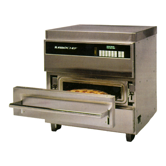
Model D Ovens
D1-EC
European
D1B-EC
European
D2-EC
European
D2B-EC
European
Revision A February 16, 1996
Revision B February 27, 1997
Please See Inside for Important
Steps before Operating Oven.
Advertisement

Subscribe to Our Youtube Channel
Related Manuals for TurboChef D1


Summary of Contents for TurboChef D1
- Page 1 Please See Inside for Important Domestic D2-EC European Steps before Operating Oven. Domestic D2B-EC European Customer Service Toll Free Number (800) 908-8726 Copyright February 15, 1995 TurboChef, Inc., All Rights Reserved Revision A February 16, 1996 Revision B February 27, 1997...
-
Page 2: Table Of Contents
TABLE OF CONTENTS Contents Page IMPORTANT SAFETY INSTRUCTIONS - READ FIRST ....4, 5 RF INTERFERENCE CONSIDERATIONS ......GROUNDING INSTRUCTIONS . - Page 3 FILTER DOOR SWITCH LOCATION / ASSEMBLY ... . 44 CONTROL ..........Electrical Enclosure Assembly .
-
Page 4: Important Safety Instructions - Read First
DO NOT use the cavity for storage purposes. DO NOT leave paper products, cooking utensils, or food in the cavity when not in use. SAVE THESE INSTRUCTIONS TurboChef, Inc. 700-0655.DOC Rev B February 15, 1997 Page 4 of 62... -
Page 5: Microwave Energy
7. A microwave leakage check to verify compliance with the Federal Performance Standard MUST BE performed on each oven prior to release to the owner. SAVE THESE INSTRUCTIONS TurboChef, Inc. 700-0655.DOC Rev B February 15, 1997 Page 5 of 62... -
Page 6: Rf Interference Considerations
If the power supply cord is damaged, it MUST BE replaced by the manufacturer or its service agent or a similarly qualified person in order to avoid a hazard. SAVE THESE INSTRUCTIONS TurboChef, Inc. 700-0655.DOC Rev B February 15, 1997 Page 6 of 62... -
Page 7: Installation
The machined door flange on the previous model became a formed part. D2-EC Oven (European) Serial Numbers 10141 through 10210. Extension of D1-A. The height of the cook chamber increased from 4” to 5.25” to allow cooking of a greater variety of foods. Heater element terminals extend through the top cover of the heat exchanger rather than the left side, for easier assembly. -
Page 8: Installation Instructions
WARNING a) DEATH, INJURY, AND EQUIPMENT DAMAGE could result from improper installation of the TurboChef oven or installation of a unit which has been damaged during shipment or storage. Either of these conditions could void the equipment warranty. b) DO NOT INSTALL a TurboChef oven suspected of damage. -
Page 9: Specifications
Specifications 1.3.1 Physical characteristics: D1 Models D2 Models Width: 31.5” 31.5” Height: 39.0” 41.3” Depth: 35.5” 35.5” Weight: 534 lb. 540 lb. 1.3.2 Electrical Characteristics: Characteristic Domestic Models EC Models Voltage: 208-240 Volts AC, 60 Hz 400-415 Volts AC, 50 Hz... -
Page 10: Operating Instructions
RESUME - Continues Cook Cycle if interrupted such as by opening oven door. TW - Percent of Microwave used during a Cook Event. WARM-UP Mode - Mode that brings the oven up to the Cook Temperature Set Point. TurboChef, Inc. 700-0655.DOC Rev B February 15, 1997 Page 10 of 62... -
Page 11: Basic Operation Instructions (Version R Software)
3. Close cooking chamber door by pushing forward on the handle until the door shuts, then push the handle down to latch into place. 4. Press the desired food (group) Cook Setting button. TurboChef, Inc. 700-0655.DOC Rev B February 15, 1997 Page 11 of 62... - Page 12 The "STOP" key can be utilized to stop the Cook Setting at any point in the cook cycle. The Cook Setting may be continued by pressing the "RESUME" key. The "STOP" key is also used to exit other modes such as "EDIT" or "MAINTENANCE". TurboChef, Inc. 700-0655.DOC Rev B February 15, 1997 Page 12 of 62...
-
Page 13: Developing Cook Settings And Programming
When you get a list of cook settings you are happy with, write them down and store the list in a safe place. 1. TurboChef uses a moving shroud of hot air to surround the food. This locks in the food’s moisture. - Page 14 6. Observe the three parameters for cook event 1. The blinking cursor indicates the Event Duration is selected for editing. Use the left/right arrow keys to select the other parameters, blower power (AIR) or microwave power (TW). TurboChef, Inc. 700-0655.DOC Rev B February 15, 1997 Page 14 of 62...
- Page 15 TEMP TOO LOW message. CAUTION: DO NOT leave the heaters on for long periods, as the oven will rapidly heat to maximum allowed temperature (Approximately 700° ° ° ° F(371°C)). TurboChef, Inc. 700-0655.DOC Rev B February 15, 1997 Page 15 of 62...
- Page 16 If the EC thermocouple is open or missing, “EC THERMO OPEN” is displayed. The EC temperature should not exceed 140°F(60°C) under normal conditions. TurboChef, Inc. 700-0655.DOC Rev B February 15, 1997 Page 16 of 62...
- Page 17 OFF, the blower controller is returned to the ON or operational state and the air flow is set to the IAF setting before returning to normal cooking operation. TurboChef, Inc. 700-0655.DOC Rev B February 15, 1997 Page 17 of 62...
-
Page 18: Control Panel Layout
* LED 11 is not connected on early “B” Version Ovens, LED 11 is connected on ovens with Serial Numbers greater than 100,000. † LED’s 12 and 13 are connected on “B” Version Ovens only. TurboChef, Inc. 700-0655.DOC Rev B February 15, 1997 Page 18 of 62... -
Page 19: Troubleshooting
6. “Mag 1 (2) CURRENT LOW” 5.4 7. “Mag 1 (2) RF FLUC LOW” 8. “Mag 1 (2) THERMO SW” 9. “Oven Door Open” 10. “Filter Door Open” 11. “Keypad DEFECTIVE” TurboChef, Inc. 700-0655.DOC Rev B February 15, 1997 Page 19 of 62... - Page 20 Page 1. “BMSC DEFECTlVE” 2. “COOK TEMP TOO LOW” 4.7 3. “EC Temp ___ °F” 4. “Mag CURRENT LOW” 5. “Mag RF FLUC LOW” 6. “Mag THERMO SW” TurboChef, Inc. 700-0655.DOC Rev B February 15, 1997 Page 20 of 62...
-
Page 21: Self Test Flow Chart
3.3 Self Test Flow Chart TurboChef, Inc. 700-0655.DOC Rev B February 15, 1997 Page 21 of 62... - Page 22 TurboChef, Inc. 700-0655.DOC Rev B February 15, 1997 Page 22 of 62...
-
Page 23: On-Line Flow Chart
3.4 On-Line Flow Chart TurboChef, Inc. 700-0655.DOC Rev B February 15, 1997 Page 23 of 62... -
Page 24: Convection System
8-32 X .25 LG. SET SCREW, SOCKET HD, SS 700-1177 GRAPHITE BLOCK, BEARING SEAL 101733 SPRING, COMPRESSION, SS 700-1179 CLAMP, BEARING SPRING 101005 10-32 NUT, LOCK, CRES 102140 # 10 FLAT WASHER 102350 #10 SPLIT LOCK TurboChef, Inc. 700-0655.DOC Rev B February 15, 1997 Page 24 of 62... -
Page 25: Blower Motor Controller Tests
Note: The Blower Shaft rotates in the clockwise direction when viewed from front of oven. Blower Defective Messages The TurboChef oven will display a defective (fail) message, “BMSC DEFECTIVE”, if the RUN status from the Blower Motor Speed Controller is absent during self-test or while cooking. -
Page 26: Blower Motor Controller Defective Messages
Check Blower shaft to see if it freely turns. Check the Oven Air Filter and verify the Floor Fan is operating (If the oven is hot). Refer to the blower motor/controller test. TurboChef, Inc. 700-0655.DOC Rev B February 15, 1997 Page 26 of 62... - Page 27 Codes Action AdPF, CH, diSc, EErd, EEOU, EPCH, FSF, In00, In02, In04, Replace the SP500 controller. In06, In08, In10, In15, noAd, OLP2, rSF, rEF1, rEF2, SELU, UnOP, 7rAP TurboChef, Inc. 700-0655.DOC Rev B February 15, 1997 Page 27 of 62...
-
Page 28: Blower Adjustments
230 ** 230 ** F-14 F-29 ---- ---- ---- F-49 ---- ---- 3.01 * 3.10 * * Read only setting. ** Factory set. Do not change. *** PW=257 (Password) TurboChef, Inc. 700-0655.DOC Rev B February 15, 1997 Page 28 of 62... -
Page 29: Heat Exchanger
CAUTION: DO NOT leave the heaters on for long periods, as the oven will rapidly heat to maximum allowed temperature (approximately 720° ° ° ° F (382° ° ° ° C)). REAR VIEW OF OVEN TurboChef, Inc. 700-0655.DOC Rev B February 15, 1997 Page 29 of 62... - Page 30 BUSS BAR, NEUTRAL, Y, 415 V 700-0454-3 BUSS BAR, REAR, 3 PHASE, Y, 415 V 700-0455-3 BUSS BAR, CENTER, 3 PHASE, Y, 415 V 700-0456-3 BUSS BAR, FRONT, 3 PHASE, Y, 415V TurboChef, Inc. 700-0655.DOC Rev B February 15, 1997 Page 30 of 62...
- Page 31 700-0380 BUSS BAR, NEUTRAL, Y, 415 V 700-0456-1 BUSS BAR, INPUT, REAR, 3 PHASE 700-0455-1 BUSS BAR, INPUT, CENTER, 3 PHASE 700-0454-1 BUSS BAR, INPUT, FRONT, 3 PHASE TurboChef, Inc. 700-0655.DOC Rev B February 15, 1997 Page 31 of 62...
-
Page 32: Heat Exchanger Defective Messages
1. Display Reading 77°(25° ° ° ° C) (Room Temperature) Acceptable condition from a cold start. 2. Display Reading 999°(999° ° ° ° C) Indicates related thermocouple is open. Check thermocouple connections. TurboChef, Inc. 700-0655.DOC Rev B February 15, 1997 Page 32 of 62... -
Page 33: Microwave System
If further information is required for this test, please call the TurboChef, Inc. Customer Service Toll Free Number listed on the front of this manual. -
Page 34: How To Turn Magnetrons On/Off For Testing
10 seconds. If the difference between the maximum sample and minimum sample is less than 50 units during self-test or 20 units during cooking, the error message “RF FLUC LOW” will be displayed. TurboChef, Inc. 700-0655.DOC Rev B February 15, 1997 Page 34 of 62... -
Page 35: Microwave Component Locations
WASHER, LOCK, SPLIT, SS, #6 102380 WASHER, SPLIT LOCK, SS, #6 101590 SCREW, PPH, SS, #6-32 X.38 102170 WASHER, FLAT, SS, #6 101590 SCREW, PPH, SS, #6-32 X.38 100690 INSULATOR, THERMAL SWITCH TurboChef, Inc. 700-0655.DOC Rev B February 15, 1997 Page 35 of 62... -
Page 36: Microwave Error Messages
3. Check Air Filter to see if is 212°F (100°C). stopped up or dirty. 4. Check proper operation of magnetron blower (Note: Mag. operates only when magnetrons are on.) TurboChef, Inc. 700-0655.DOC Rev B February 15, 1997 Page 36 of 62... -
Page 37: Magnetron
3. An ohmmeter connected between the filament terminals (F, FA) should indicate a reading of less than 1 Ohm. 4. A continuity check between either filament terminal and the magnetron chassis should indicate an infinite resistance (open). TurboChef, Inc. 700-0655.DOC Rev B February 15, 1997 Page 37 of 62... -
Page 38: High Voltage Magnetron Transformer
2. Isolate the transformer from the circuit. (Wires are labeled but remember where they 3. Check impedance of the primary and secondary windings. ( See above.) 4. Filament winding should read less than 0.1 ohms. 5. Reconnect wires. TurboChef, Inc. 700-0655.DOC Rev B February 15, 1997 Page 38 of 62... -
Page 39: High Voltage Diode
Caution: After removing the oven from power and prior to servicing the oven, discharge the capacitor. Never assume the discharge resistor internal to the capacitor has completely discharged the capacitor. TurboChef, Inc. 700-0655.DOC Rev B February 15, 1997 Page 39 of 62... -
Page 40: Microwave Mode Stirrer
The stirrer motor is a 240 VAC synchronous motor that turns at 7.2 rpm (6 rpm in 50 Hz units). MICROWAVE MODE STIRRER ASSEMBLY TurboChef, Inc. 700-0655.DOC Rev B February 15, 1997 Page 40 of 62... -
Page 41: Magnetron Over-Temperature Switch
50 units to pass self-test and 20 units to pass the on-line tests (while cooking). The Mode Stirrer rotates once every 8.3 seconds (10 seconds for 50 Hz units). RF OUTPUT MONITOR CIRCUIT TurboChef, Inc. 700-0655.DOC Rev B February 15, 1997 Page 41 of 62... -
Page 42: Cook Door Assembly
4-40 X .25 LG. SCREW, PPH, SS 700-0422-1 RAIL, SLIDE, FRONT 700-1169 DOOR PIN RETAINING PLATE 102400 WASHER, LOCK, SPLIT, SS, 1/4 * SOME MODELS USE DIFFERENT HARDWARE TO ATTACH COVER. TurboChef, Inc. 700-0655.DOC Rev B February 15, 1997 Page 42 of 62... -
Page 43: Cook Door And Interlock Switch Adjustments
1/2 WASHER, FLAT, SMALL PATTERN 700-0567 BEARING, FLANGE, MODIFIED 101550 SCREW, PPH, SS, #4-40 X .625 102370 WASHER, LOCK, SPLIT, SS, #4 102240 WASHER, FLAT, SMALL PATTERN, SS, #4 TurboChef, Inc. 700-0655.DOC Rev B February 15, 1997 Page 43 of 62... -
Page 44: Filter Door Switch Location / Assembly
10-32 X .75 LG. SCREW, PPH, SS 102350 #10 WASHER, LOCK, SPLIT 102140 #10 WASHER, FLAT 100400 BEARING 700-0530-1 STIFFENER PLATE, FILTER DOOR RIGHT 102015 MICROSWITCH NOTE: SHOWN WITH FILTER DOOR, 700-0615, REMOVED. TurboChef, Inc. 700-0655.DOC Rev B February 15, 1997 Page 44 of 62... -
Page 45: Control
RELAY, POWER 101017 SWITCH, THERMAL LIMIT, 600°F, OT1 700-0399 CABLE, EXTENSION, RS-232 100440 CONTROLLER, MOTOR, SP 500 100660 I/O CIRCUIT CARD ASSY, D1/D1A/D2 SERIES 80849 I/0 CIRCUIT CARD ASSY, D1B/D2B SERIES 101205 POWER SUPPLY 102085 THERMOSTAT 120°F, OT2 100490 DISTRIBUTION BLOCK, MB4/6.L3... -
Page 46: Electrical Enclosure Diagnostic Message
ITEM PART NO. DESCRIPTION 700-0269 CONTROLLER, ENCLOSURE 700-0328 KEYPAD 100430 CONTROLLER CIRCUIT CARD ASSY, D1/D1A/D2 SERIES 80846 CONTROLLER CIRCUIT CARD ASSY, D1B/D2B SERIES 4 ** 700-0650 IC, EPROM, SOFTWARE NOTE: PLEASE SPECIFY SOFTWARE VERSION WHEN ORDERING 101520 4-40 X .25 LG. SCREW, PPH, SS... -
Page 47: Mag. Fan/Cooling Fan/Transformers/Diodes/Caps
WASHER, FLAT, SMALL PATTERN, #6 102687 CAPACITOR, RUN, 4.0 uF, 400V ** NOTE: MAGNETRON CAPACITORS, C1 & C2, ARE LOCATED ON TOP OF MAGNETRON COOLING FAN ASSEMBLY ON LATER OVENS. TurboChef, Inc. 700-0655.DOC Rev B February 15, 1997 Page 47 of 62... -
Page 48: Where And How To Obtain Parts
SERIAL NUMBER OF THE OVEN (REFER TO 1.1 FOR HELP). 2. WE WILL SHIP PREPAID AND INVOICE YOU FOR THE CHARGES. 3. TURBOCHEF WILL ADD APPLICABLE SHIPPING CHARGES FOR ALL PURCHASE PARTS. 4. PLEASE CIRCLE DESIRED METHOD OF SHIPMENT: •... -
Page 49: Returning Critical Components
TurboChef, Inc. by giving the model and serial number of the oven and a brief description of the part. If there is any question about substitute parts, feel free to contact the Customer Service Toll Free Number given on the front cover for assistance. -
Page 50: Case History
CHECK FOR A POSSIBLE SHORT IN THE CIRCUIT FOR THE POWER SUPPLY (CHASSIS IS 24 VDC GROUND). CHECK FOR LOOSE CONNECTORS OR WIRES. CHECK FOR PROPER INSTALLATION OF SOFTWARE (EPROM). TurboChef, Inc. 700-0655.DOC Rev B February 15, 1997 Page 50 of 62... - Page 51 CHECK POWER SUPPLY INPUT & OUTPUT. CHECK ALL CONNECTIONS AT THE INTERLOCK SWITCHES FOR ANY ERRATIC BEHAVIOR (SUCH AS LOOSE WIRES OR OPEN SWITCHES). CHECK INCOMING POWER TO THE OVEN. TurboChef, Inc. 700-0655.DOC Rev B February 15, 1997 Page 51 of 62...
-
Page 52: Diagnostic Information (Including Schematics)
Schematic Title D1B/D2B 700-0357 Schematic, D1B/D2B Oven, 3Ø, 4W, 208-240 VAC D1B-EC/D2B-EC 700-0358 Schematic, D1B-EC/D2B-EC Oven, 3Ø, 5W, 400-415 VAC D1-EC/D2-EC 700-0398 Schematic, Oven, 3Ø, 5W, 400-415 VAC, 50 HZ D1/D1A/D2 700-0425 Schematic, Oven, 3Ø, 4W, 208-240 VAC TurboChef, Inc. - Page 53 TurboChef, Inc. 700-0655.DOC Rev B February 15, 1997 Page 53 of 62...
- Page 54 TurboChef, Inc. 700-0655.DOC Rev B February 15, 1997 Page 54 of 62...
- Page 55 TurboChef, Inc. 700-0655.DOC Rev B February 15, 1997 Page 55 of 62...
- Page 56 TurboChef, Inc. 700-0655.DOC Rev B February 15, 1997 Page 56 of 62...
- Page 57 TurboChef, Inc. 700-0655.DOC Rev B February 15, 1997 Page 57 of 62...
- Page 58 TurboChef, Inc. 700-0655.DOC Rev B February 15, 1997 Page 58 of 62...
- Page 59 TurboChef, Inc. 700-0655.DOC Rev B February 15, 1997 Page 59 of 62...
- Page 60 TurboChef, Inc. 700-0655.DOC Rev B February 15, 1997 Page 60 of 62...
-
Page 61: Limited Warranty For "D" Series Ovens
(including negligence), product liability or otherwise, even if TurboChef or its representatives have been advised of the possibility of such damages and even if a remedy set forth herein is found to have failed in its essential purpose. Such damage includes any act or omission by a party other than TurboChef, which causes undue or accelerated component wearing, operational complications, and/or general component/system failure. -
Page 62: Appendix A
DB9 Female DB9 Female TX DATA > < RX DATA < SIG GND > Data Format: RS 232, 1 Start Bit, 8 Data Bits, 1 Stop Bit, 19,200 Baud. TurboChef, Inc. 700-0655.DOC Rev B February 15, 1997 Page 62 of 62...
Need help?
Do you have a question about the D1 and is the answer not in the manual?
Questions and answers