Table of Contents
Advertisement
Advertisement
Table of Contents

Related Manuals for Novus NV-DVR5009


Summary of Contents for Novus NV-DVR5009
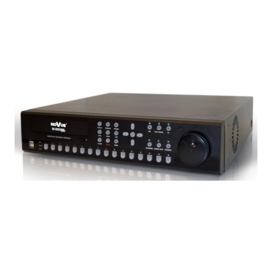
- Page 1 U s e r ’s m a n u a l NV-DVR5009 NV-DVR5016...
- Page 2 ACCORDING TO DEVICE OPERATION RULES BASED ON CMOS/MOSFET SYSTEMS. INFORMATION All the data included in this manual are up to date at the moment of printing this manual. Novus Security Sp. z o.o. reserves the right to amend this manual. The producer reserves the right to modify recoreder’s parameters and change its design without notice.
- Page 3 4. The recorder has to be protected against humidity and dust. In case the recorder had a contact with water react immediately: switch off the power supply and contact the authorised Novus service. If the device gets dirty it might get damaged or electrocute someone.
-
Page 4: Table Of Contents
NV-DVR5009 / NV-DVR5016 1.0 version - User’s manual TABLE OF CONTENTS 1. FOREWORD INFORMATION....................6 1.1 Main Characteristics......................6 1.2 Recorder’s technical data ....................7 2. STARTING THE DEVICE....................... 8 2.1 Getting the device ready to work ..................8 2.2 Electrical connection and other back panel elements ............9 2.3 Connecting of peripheral equipment................ - Page 5 NV-DVR5009 / NV-DVR5016 1.0 version - User’s manual TABLE OF CONTENTS 4.6 Image adjustment ......................52 4.7 Event monitoring ......................53 4.8 Covert cameras ........................ 53 4.9 Spot monitors........................53 4.10 Using a mouse ....................... 53 4.11 Recording video......................55 4.12 Recording audio......................
-
Page 6: Foreword Information
FOREWORD INFORMATION FOREWORD INFORMATION NV-DVR5009 (9-channel) and NV-DVR5016 (16-channel) recorders were designed especially for CCTV systems. A very efficient MPEG4 compression is used in this device that guarantees high quality, detailed images. The device allows high quality recording for a long period of time. It also allows to flexibly adjust recording parameters depending on system requirements. -
Page 7: Recorder's Technical Data
Operating system: Linux PTZ functions: Possibility of PTZ camera controlling (48 protocols NOVUS-C among others) from the level of recorders without the necessity to use an additional keyboard, and through the computer network with the help of RAS software Video inputs:... -
Page 8: Starting The Device
NV-DVR5009 / NV-DVR5016 1.0 version - User’s manual STARTING THE DEVICE STARTING THE DEVICE 2.1. Getting the device ready to work Unpack the device carefully. After unpacking make sure that there are the following elements: IR remote control. NV-DVR5009 or NV-DVR5016 rcorder. -
Page 9: Electrical Connection And Other Back Panel Elements
NV-DVR5009 / NV-DVR5016 1.0 version - User’s manual STARTING THE DEVICE 2.2. Electrical connection and other back panel elements NV-DVR5016 View Fan cooling power supply unit, it shouldn’t be covered! VIDEO IN/LOOP: video inputs to hook up camera video signal with arterial outputs of video signal, 16 or 9 depending on the model. - Page 10 NV-DVR5009 / NV-DVR5016 1.0 version - User’s manual STARTING THE DEVICE 13 14 NV-DVR5016 View to USB ports of the device (one port in the back panel and two in the front USB Port panel) you can connect external HHDs, external CD-RW recorders or Flash memory for archiving.
- Page 11 NV-DVR5009 / NV-DVR5016 1.0 version - User’s manual STARTING THE DEVICE Ultra Wide SCSI external disk array is connected to this port. The array is used for recording or archiving camera images. The device, together with external memory, can address up to 9 TB of memory, connect Ultra Wide SCSI port to the disk array by means of a 68-pin cord not longer than 1.5 m.
-
Page 12: Connecting Of Peripheral Equipment
NV-DVR5009 / NV-DVR5016 1.0 version - User’s manual STARTING THE DEVICE 2.3. Connecting of peripheral equipment System connecting should be done by a qualified staff. Before connecting system elements you need to familiarise yourself with the diagram presented below, which is a pictorial diagram. Depending on requirements, specific system will consist of a different number peripheral devices. -
Page 13: Front Panel Description
NV-DVR5009 / NV-DVR5016 1.0 version - User’s manual STARTING THE DEVICE 2.4. Front panel description 7 8 9 Widok NV-DVR5016 Some buttons of the front panel are used for different functions. Remote control buttons, even though placed in a different way, fully correspond to the functions attributed to the front panel functions. Below, you have the description of all buttons and their functions. - Page 14 NV-DVR5009 / NV-DVR5016 1.0 version - User’s manual STARTING THE DEVICE Flickering of a green HDD LED (light-emitting diode) means that a process of recording or searching / playback is in progress. Flickering of a green NETWORK LED means that the device is connected to Ethernet or external modem.
- Page 15 NV-DVR5009 / NV-DVR5016 1.0 version - User’s manual STARTING THE DEVICE When in the playback mode, you can play video forward image- by-image by turning the Jog Dial clockwise and backward image- by-image by turning the Jog Dial counterclockwise. When in the...
- Page 16 NV-DVR5009 / NV-DVR5016 1.0 version - User’s manual STARTING THE DEVICE Pressing the PTZ button enters the PTZ (Pan/Tilt/Zoom) mode which allows you to control properly configured cameras. FREEZE Pressing the FREEZE button freezes the current live screen. SEQUENCE When in the live mode, pressing the SEQUENCE button displays live channels sequentially.
-
Page 17: Recorder's Menu
RECORDER’S MENU RECORDER’S MENU NV-DVR5009 and NV-DVR50016 recorders have multilevel menus displayed on the screen. The menu is multilingual. Depending on the implemented firmware version, it is displayed in English, German, Spanish, French and Italian, or English, Polish, Russian, Hungarian and Czech. -
Page 18: System Menu
NV-DVR5009 / NV-DVR5016 1.0 version - User’s manual RECORDER’S MENU 3.1. System menu After pressing Menu and putting in user password the following screen appears: There are six sub-menus concerning recorder’s system settings in the System menu. 3.1.1. Information After choosing this sub-menu and pressing Enter the following screen appears: Highlight the Site box and press the button. -
Page 19: System Log
NV-DVR5009 / NV-DVR5016 1.0 version - User’s manual RECORDER’S MENU Highlight the box beside Language and press button. A drop-down menu displays the available languages. Highlight the desired language and press the button. To upgrade the software, connect a USB device containing upgrade package file to the DVR. Highlight Upgrade…... -
Page 20: System Status
NV-DVR5009 / NV-DVR5016 1.0 version - User’s manual RECORDER’S MENU 3.1.1.2 System status Highlight Show Event Status and press the button to display the Event Status screen: The Event Status screen displays the status of the DVR’s systems and inputs. Events will be highlighted, and related channels or events will be flickered for five seconds when detected. -
Page 21: Recording Range
NV-DVR5009 / NV-DVR5016 1.0 version - User’s manual RECORDER’S MENU 3.1.1.3. Recording range In the recording range section you can find time frames of the recorded camera images. Highlighting Clear All Data… and pressing the button will clear all video data. -
Page 22: Disks
NV-DVR5009 / NV-DVR5016 1.0 version - User’s manual RECORDER’S MENU NOTE: Holidays that do not fall on the same date each year should be updated once the current year’s holiday has passed. You can set up holidays by highlighting + and pressing the button. - Page 23 NV-DVR5009 / NV-DVR5016 1.0 version - User’s manual RECORDER’S MENU The information in the Type column describes the storage device (internal disk, external disk with USB interface). The capacity of the storage device is displayed in the Capacity column. The Format column displays whether the device is used for recording (Record) or archiving (Archive).
- Page 24 NV-DVR5009 / NV-DVR5016 1.0 version - User’s manual RECORDER’S MENU Highlight the Status tab, and the Storage Status screen displays. The Type column displays the type of storage device. The Disk Bad column displays the percentage of bad sectors. Unformatted indicates the device is not formatted.
-
Page 25: Users
NV-DVR5009 / NV-DVR5016 1.0 version - User’s manual RECORDER’S MENU 3.1.4. Users Highlight User in the System menu and press the button. The User setup screen displays the authorized groups and users. You can add and delete groups and users. When adding a group, you can assign authority levels to the group. - Page 26 NV-DVR5009 / NV-DVR5016 1.0 version - User’s manual RECORDER’S MENU A group of users can obtain the following rights: Shutdown — The user can shut the system down on a local system. • Upgrade — The user can upgrade the software on a local system or a PC running RAS •...
-
Page 27: System Shutdown
NV-DVR5009 / NV-DVR5016 1.0 version - User’s manual RECORDER’S MENU 3.1.5. System shutdown Highlight Shutdown in the System menu and press the button. The Shutdown screen displays asking you to confirm whether or not you want to shut the system down:... -
Page 28: Network
NV-DVR5009 / NV-DVR5016 1.0 version - User’s manual RECORDER’S MENU 3.2. Network In the Main screen, use the Left or Right arrow buttons to display the Network menu. 3.2.1.1. Network Highlight Network in the Network menu and press the button. The Network setup screen displays. -
Page 29: Lan
NV-DVR5009 / NV-DVR5016 1.0 version - User’s manual RECORDER’S MENU 3.2.1.2. Highlight the LAN tab, and the LAN screen displays. Highlight the box beside Type and press the button. You can select the type of network configuration from: Manual, DHCP and ADSL (with PPPoE). Select the desired type and press the button. -
Page 30: Modem
NV-DVR5009 / NV-DVR5016 1.0 version - User’s manual RECORDER’S MENU The factory default Port settings are: Remote Admin: 8200 Remote Call-back: 8201 Remote Watch: 8016 Remote Search: 10019 NOTE: Do NOT use the same port number for two different programs, otherwise, the DVR cannot be connected with a PC running RAS. -
Page 31: Notifying
NV-DVR5009 / NV-DVR5016 1.0 version - User’s manual RECORDER’S MENU 3.2.2. Notification The DVR can be set up to send emails or to contact a computer running RAS (Remote Administration System) when an event occurs. 3.2.2.1. E-mail Highlight Notification in the Network menu and press the button. -
Page 32: Devices
NV-DVR5009 / NV-DVR5016 1.0 version - User’s manual RECORDER’S MENU 3.3. Devices You can configure the video, audio, alarm, display and remote control devices connected to the DVR. 3.3.1. Cameras Highlight Camera in the Devices menu and press the button. The Camera setup screen appears. - Page 33 485 port. To connect the keyboards and speed domes cameras simultaneously you need to use RS232 / RS485 converter. In the Product box choose a telemetry protocol from the ones which are available (e.g. Novus-C, Pelco- P and Pelco-D) and which is in accordance with PTZ camera settings.
-
Page 34: Audio
NV-DVR5009 / NV-DVR5016 1.0 version - User’s manual RECORDER’S MENU 3.3.2. Audio Highlight Audio in the Devices menu and press the button. The Audio setup screen appears. The DVR can record up to four audio inputs. In the Associated Camera box a chosen audio channel can be attributed to any vision channel. The connection has a logical character - physically audio signal can come from a microphone of another camera or from a separate microphone. - Page 35 NV-DVR5009 / NV-DVR5016 1.0 version - User’s manual RECORDER’S MENU Each alarm output can be given its own title by highlighting the box under the Title heading and pressing the button. A virtual keyboard appears allowing you to enter the title.
-
Page 36: Display
NV-DVR5009 / NV-DVR5016 1.0 version - User’s manual RECORDER’S MENU 3.3.4. Display Highlight Display in the Devices menu and press the button. The Display screen allows you to select what information will be displayed on the monitor. Highlighting an item and pressing the button toggles that item On and Off. - Page 37 NV-DVR5009 / NV-DVR5016 1.0 version - User’s manual RECORDER’S MENU You can adjust the transparency of the setup screens by highlighting Transparency and using the Left and Right arrow buttons. Once the tab OSD Margin is highlighted, the following screen will appear: With the help of slide bars Horizontal and Vertical You can adjust the horizontal and vertical margins so that text and icons will not be hidden beyond the edges of the monitor.
-
Page 38: Keyboard
NV-DVR5009 / NV-DVR5016 1.0 version - User’s manual RECORDER’S MENU Highlight the Spot monitor tab and the following screen will appear: You can define which cameras display sequentially on the Spot Monitors. Highlight the box in the Channels column for the desired Spot Monitor and press the button. -
Page 39: Recording
NV-DVR5009 / NV-DVR5016 1.0 version - User’s manual RECORDER’S MENU 3.4. Recording In the Recording menu there are 4 submenus concerning recording settings. 3.4.1. Record Highlight Record in the Record menu and press the button. The Record setup screen appears. - Page 40 NV-DVR5009 / NV-DVR5016 1.0 version - User’s manual RECORDER’S MENU Resolution settings are defined globally for the complete system. NOTE: Recording speed decreases by half when resolution is increased from standard 360 x 288 to 720 x 288 . Highlight the Event Record Dwell box and set the length of time you would like to record for the associated event.
-
Page 41: Schedule
NV-DVR5009 / NV-DVR5016 1.0 version - User’s manual RECORDER’S MENU 3.4.2. Schedule Highlight the Schedule submenu and the following screen will appear: This DVR allows you to create very complex recording schedules in order to adjust recording settings to the specificity of the object and to save disk space. The Schedule is presented as a easy to read table. -
Page 42: Pre-Event
NV-DVR5009 / NV-DVR5016 1.0 version - User’s manual RECORDER’S MENU Under the Settings heading, recording speed should be defined in the range between 0.1 to 25 frames per second, as well as recording quality: Highest, High, Standard and Low. By choosing the X option, a selected point of the Schedule may be erased. -
Page 43: Archive
NV-DVR5009 / NV-DVR5016 1.0 version - User’s manual RECORDER’S MENU 3.4.4. Archive Highlight Archive in the Record menu and press the button, and the Archive setup screen appears. Highlight Archive On and press the button to toggle between On and Off. -
Page 44: Event
NV-DVR5009 / NV-DVR5016 1.0 version - User’s manual RECORDER’S MENU 3.5. Event Your DVR can be set to detect many different events. You can also determine how it reacts to these events. 3.5.1. Alarm-in. Highlight Alarm-In in the Event menu and press the button. - Page 45 NV-DVR5009 / NV-DVR5016 1.0 version - User’s manual RECORDER’S MENU Highlight the Actions tab, and the Actions setup screen appears In the Actions tab, the user may set the DVR response to the activation of a chosen alarm-in. Highlight the desired box under the Record heading, and press the button.
-
Page 46: Motion Detection
NV-DVR5009 / NV-DVR5016 1.0 version - User’s manual RECORDER’S MENU 3.5.2. Motion detection Highlight Motion Detection in the Event menu and press the button. The Motion Detection setup screen appears: His DVR has a built-in video motion detection. In the No. column this motion detection can be turned on and off for each camera. -
Page 47: Video Loss
NV-DVR5009 / NV-DVR5016 1.0 version - User’s manual RECORDER’S MENU Reverse All — Activates inactive blocks and deactivates active blocks. • OK — Accepts changes and closes Zone setup. • Cancel — Exits Zone setup with saving changes. • You can adjust the minimum number of detection blocks that must be activated to trigger a motion alarm. -
Page 48: System Event
NV-DVR5009 / NV-DVR5016 1.0 version - User’s manual RECORDER’S MENU 3.5.4. System event Highlight System Event in the Event menu and press the button. The System Event setup screen appears. The DVR can be configured to run self-diagnostics and report the results. - Page 49 NV-DVR5009 / NV-DVR5016 1.0 version - User’s manual RECORDER’S MENU Highlight the box beside Check Time, and press the button. You can select from Monthly, Weekly and Daily. If you select Monthly, you will be asked to set the Day of the Month and Time. If you select Weekly, you will be asked to set the Day of the Week and Time.
-
Page 50: Recorder's Operation
NV-DVR5009 / NV-DVR5016 1.0 version - User’s manual RECORDER’S OPERATION MULTIPLEXER’S OPERATION 4.1. Live monitoring As soon as the DVR completes its initialization process, it will begin showing live video on the attached monitor and playing live audio through attached speakers. The default mode is to display all cameras at once (16 or 9 depending on the DVR model). -
Page 51: Active Cameo Mode
NV-DVR5009 / NV-DVR5016 1.0 version - User’s manual RECORDER’S OPERATION 4.2. Active Cameo Mode You can enter the Active Cameo mode by pressing the button in any multi-view format. The yellow outline surrounding the video indicates the active cameo, and pressing the arrow buttons moves the active cameo. -
Page 52: Image Adjustment
NV-DVR5009 / NV-DVR5016 1.0 version - User’s manual RECORDER’S OPERATION To program a preset, direct the camera at a selected scene and press Enter. When the PTZ dialog box appears, select the number you want to assign to the preset and press the button. -
Page 53: Event Monitoring
NV-DVR5009 / NV-DVR5016 1.0 version - User’s manual RECORDER’S OPERATION 4.7. Event monitoring When an event occurs, the DVR will display the camera associated with the event if Event Monitoring On is selected in the Display setup screen (OSD tab). - Page 54 NV-DVR5009 / NV-DVR5016 1.0 version - User’s manual RECORDER’S OPERATION Clicking the right mouse button during live monitoring displays the following menu: Selecting Freeze, PTZ… and Spot Monitor… is the same as pressing the FREEZE, PTZ and SPOT buttons as described above in the Live Monitoring section of this chapter.
-
Page 55: Recording Video
NV-DVR5009 / NV-DVR5016 1.0 version - User’s manual RECORDER’S OPERATION 4.11. Recording video Maximum recording speed of images in 360 x 288 resolution (PAL) is 200 images / s. for the complete system. Maximum recording speed of images in 720 x 288 resolution (PAL) is 100 images / s. for the complete system. -
Page 56: Searching Video
NV-DVR5009 / NV-DVR5016 1.0 version - User’s manual RECORDER’S OPERATION SEARCH / STOP - Pressing the SEARCH/STOP button while in the Playback mode returns the DVR to the Live Monitoring mode. Pressing the SEARCH/STOP button while in the Live Monitoring mode returns the DVR to the Search mode. -
Page 57: Go To The Date/Time
NV-DVR5009 / NV-DVR5016 1.0 version - User’s manual RECORDER’S OPERATION Calendar Search… — Searches using a calendar (see below for more details); • Event Log Search… — Selects video from the event log (see below for more details) • Text-In Search… — Searches text input strings (see below for more details) •... -
Page 58: Event Log Search
NV-DVR5009 / NV-DVR5016 1.0 version - User’s manual RECORDER’S OPERATION Days with recorded video display are displayed in the calendar in white. You can highlight the days with recorded video by using the arrow buttons. Once you have highlighted a day, press the button to select it. - Page 59 NV-DVR5009 / NV-DVR5016 1.0 version - User’s manual RECORDER’S OPERATION You can search video from the first to last recorded images, or you can set the start and stop times and dates. For this last purpose serve the From and To options.
-
Page 60: Motion Search
NV-DVR5009 / NV-DVR5016 1.0 version - User’s manual RECORDER’S OPERATION 4.14.4. Motion search Once his function is selected, the following screen will appear: The Motion Search can be selected from the Search menu while the DVR displays the camera full screen. -
Page 61: Clip Copy
NV-DVR5009 / NV-DVR5016 1.0 version - User’s manual RECORDER’S OPERATION 4.15. Clip Copy The Clip-Copy screen can be used to copy video clips to an internal CD-RW drive, or external USB hard disk drive, CD-RW drive or flash drive. The copied video clips can be viewed on computers running Microsoft Windows 98, ME, 2000 or XP. -
Page 62: Print Screen
NV-DVR5009 / NV-DVR5016 1.0 version - User’s manual RECORDER’S OPERATION Once you have given the video clip a file name, highlight the Start button and press the button to start clip copy. When the storage device does not have enough space, the DVR will ask if you want to copy as much of the video clip as possible on the available space. -
Page 63: Playback
NV-DVR5009 / NV-DVR5016 1.0 version - User’s manual RECORDER’S OPERATION 4.17. Playback You do not need to install any special software on your personal computer to review the video clips. The copied video clip contains the ClipPlayer program. NOTE: It is suggested that the computer used for the ClipPlayer program has at least a 800MHz Pentium III. - Page 64 NV-DVR5009 / NV-DVR5016 1.0 version - User’s manual RECORDER’S OPERATION And then select Advanced Troubleshoot then set the Hardware Acceleration to “Full”. Please make sure that DirectX version 8.0 or higher has been installed if the display problem continues to occur. To check the version of DirectX, click Start à RUN and type “dxdiag” then hit the enter key which will display DirectX Diagnostic Tool dialog box.
- Page 65 NV-DVR5009 / NV-DVR5016 1.0 version - User’s manual RECORDER’S OPERATION Program functions description: Clicking the X exits the Player program. Click the to go to the beginning of the video clip. Click the to play the video clip in fast reverse.
-
Page 66: Appendix 1 Ptz Cameras Control And Connection
NV-DVR5009 / NV-DVR5016 1.0 version - User’s manual PTZ CAMERAS CONTROL AND CONNECTION Appendix 1: Novus camera connection Recorder To RS-485+ and RS-485– ports Control cable Rx+(Tx+) Rx- (Tx -) Rx+(Tx+) Rx- (Tx -) Przewód wizyjny Novus Novus CAMA I... -
Page 67: Appendix 2 Connecting Devices To Alarm Inputs And Outputs
Appendix 2: Connecting devices to alarm inputs and outputs. NV-DVR5009 and NV-DVR5016 recorders have 9 or 16 alarm inputs and out allowing you to connect external devices. Connectors to plug in cables are equipped with handy clamp terminals. NOTE: Both alarm inputs and outputs are not protected against any results of atmospheric discharges. -
Page 68: Keyboard
Appendix 3: Recorder’s control from the level of NV-KBD60 system keyboard NV-DVR5009 and NV-DVR5016 recorders can be remotely controlled from the level of NV-KBD60 system keyboard. The control is done through the RS-422 port. Thanks to that, it is possible to control many recorders (up to 10) by using just one keyboard. -
Page 69: Appendix 4 Displaying Text On The Image
Appendix 4: Displaying text on the image NV-DVR5009 and NV-DVR5016 Series recorders are able to link and simultaneously display re- corded images and text in ASCII format by means of peripheral devices such as cash registers, cash machines or PCs with installed access control software. The recorder can work with up to 10 pe- ripheral devices that generate text and are connected to RS-232, RS-485 and USB ports (the possibility of connecting 8 devices through a divider). - Page 70 NV-DVR5009 / NV-DVR5016 1.0 version - User’s manual DISPLAYING TEXT ON THE IMAGE After highlighting the above menu the below image will be displayed on the screen. NV-DVR5009 and NV-DVR5016 s can be programmed in such a way that when they re- recorder ceive a defined string form peripheral devices, they should undertake specific actions e.g.
- Page 71 NV-DVR5009 / NV-DVR5016 1.0 version - User’s manual DISPLAYING TEXT ON THE IMAGE After highlighting Settings the below tab appears on the screen: In the Port position you need to define a type of an input, where text data will come. You can choose from RS-232, RS-485 or 8 USB ports.
- Page 72 NV-DVR5009 / NV-DVR5016 1.0 version - User’s manual DISPLAYING TEXT ON THE IMAGE In the Ignore position you define strings, whose detection is totally ignored by the system. If there are both small and capital letters of different characteristic in the system you need to tick off Case Sensitive.
- Page 73 NV-DVR5009 / NV-DVR5016 1.0 version - User’s manual DISPLAYING TEXT ON THE IMAGE After choosing a required result and choosing Enter the first image of a registered transaction with a keyword is displayed. By choosing PLAY you start playback of the registered material connected with the transaction.
- Page 74 NV-DVR5009 / NV-DVR5016 1.0 version - User’s manual NOVUS Security Sp. z o.o. ul. Puławska 431, 02-801 Warszawa tel.: (22) 546 0 700, fax: (22) 546 0 719 www.novuscctv.com v. 1.0 2006-02-08 All rights reserved © NOVUS Security Sp. z o.o.
Need help?
Do you have a question about the NV-DVR5009 and is the answer not in the manual?
Questions and answers