Table of Contents
Advertisement
Quick Links
Quick Guide
XX249-41-00
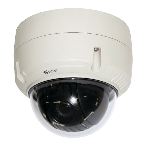
Cruiser™ SN663V-A Outdoor PTZ
Network Camera Dome
Vicon Industries Inc.
Tel: 631-952-2288 Fax: 631-951-2288 Toll Free: 800-645-9116
24-Hour Technical Support: 800-34-VICON (800-348-4266) UK: 44/(0) 1489-566300
Vicon Industries Inc. does not warrant that the functions contained in this equipment will meet your requirements or that the
operation will be entirely error free or perform precisely as described in the documentation. This system has not been designed
to be used in life-critical situations and must not be used for this purpose.
www.vicon-security.com
Document Number: 8009-8249-41-00
Issued: 215
Product specifications subject to change without notice.
Copyright © 2015 Vicon Industries Inc. All rights reserved.
Advertisement
Table of Contents

Related Manuals for Vicon Cruiser SN663V-A


Summary of Contents for Vicon Cruiser SN663V-A
- Page 1 24-Hour Technical Support: 800-34-VICON (800-348-4266) UK: 44/(0) 1489-566300 Vicon Industries Inc. does not warrant that the functions contained in this equipment will meet your requirements or that the operation will be entirely error free or perform precisely as described in the documentation. This system has not been designed to be used in life-critical situations and must not be used for this purpose.
- Page 3 1 Introduction The SN663V-A network camera is an outdoor PTZ camera dome that includes a 1080p high resolution camera lens combination that provides video transmission over a network. It is fully featured for security surveillance and remote monitoring needs. The network camera supports H.264 compression technology as well as M-JPEG compres- sion.
-
Page 4: Key Features
1.2 Key Features Brilliant video quality The network camera offers the highly efficient H.264 video compression, which drasti- cally reduces bandwidth and storage requirements without compromising image qual- ity. Motion JPEG is also supported for increased flexibility. Dual or Triple Streams The network camera can deliver dual or triple video streams simultaneously at full frame rate in all resolutions up to Full-HD (1920 x 1080p) using Motion H.264 and JPEG. -
Page 5: Installation
2 Installation 2.1 Installation The dome camera is for use in surface or pendant mounting applications, and the mounting member must be capable of supporting loads of up to 10 lb (4.5 kg). (Pendant mounting must use pendant mount accessory.) The dome cameras mounting bracket should be attached to a structural object, such as hard wood, wall stud or ceiling rafter that supports the weight of the dome camera. - Page 6 CAUTION: Before installing mounting bracket to surface pre-adjust the four mounting screws ”A” on the base of the dome camera to best match the mounting bracket locked position. Unscrew the locking screw on the side of the dome’s base and fit the tab of the mounting bracket into the locking slot.
-
Page 7: Basic Configuration Of Camera System
2.2 Basic Configuration of Camera System Connector Wire Color Description 24VAC or 12VDC+ 3-pin terminal block WHITE 24VAC or 12VDC- PINK ALARM INPUT 1 GRAY ALARM INPUT 2 GREEN ALARM INPUT 3 6-pin terminal block BLUE ALARM INPUT 4 BROWN YELLOW ALARM OUTPUT Ethernet, RJ-45 port compatible with... -
Page 8: Micro-Sd Card Insertion
2.3 Micro-SD Card Insertion User can install and change Micro-SD card as shown in the following picture. 1. Open the Micro-SD card cover. 2. Install or change Micro-SD card. 3. Tightly close the Micro-SD card cover to ensure waterproofness. - Page 9 2.4 Connections Connecting the Network Connect a standard RJ-45 cable to the network port of the camera. Generally a cross- over cable is used for directly connection to PC, while a direct cable is used for con- nection to a hub. Connecting Alarms –...
- Page 10 2.4.1 Network Connection & IP assignment The network camera is designed for use on an Ethernet network and requires an IP ad- dress for access. Most networks today have a DHCP server that automatically assigns IP addresses to connected devices. By the factory default, your camera is set to obtain the IP address automatically via DHCP server.
-
Page 11: Operation
3 Operation The network camera can be used with Windows operating system and browsers. The rec- ommended browsers are Internet Explorer, Safari, Firefox, Opera and Google Chrome with Windows. NOTE: To view streaming video in Microsoft Internet Explorer, set your browser to allow ActiveX controls. -
Page 12: Access From The Internet
3.2 Access from the internet Once connected, the network camera is accessible on your local network (LAN). To access the network camera from the Internet you must configure your broadband router to allow incoming data traffic to the network camera. To do this, enable the NAT traversal feature, which will attempt to automatically configure the router to allow access to the network cam- era. -
Page 13: Live View Page
3.4 Live View Page The Live View page comes in several screen modes: 1920x1080, 1280x1024, 1280x720(960), 1024x768, 704x480(576), 640x480(360) and 320x240. Users are allowed to select the most suitable one out of those modes. Adjust the mode in accordance with your PC specifications and monitoring purposes. - Page 14 2) Control toolbar The live viewer toolbar is available in the web browser page only. It displays the following buttons: The Stop button stops the video stream being played. Pressing the key again toggles the start and stop. The Start button connects to the network camera or starts playing a video stream.
- Page 15 3.5 Playback The Playback window contains a list of recordings made to the memory card. It shows each recording’s start time, length, the event type used to start the recording, calendar and time slice bar indicates if the recording is existed or not. The description of playback window follows.
- Page 16 (3) Time Chart Display an hour-based search screen for the chosen date. If there is recording data, a blue section will be displayed on a 24-hour basis. If you select a particular hour in the chart, a yellow square on the hour will be displayed. (4) Speaker Control Bar Use this scale to control the volume of the speakers.
-
Page 17: Network Camera Setup
3.6 Network Camera Setup This section describes how to configure the network camera. Administrator has unrestricted access to all the Setup tools, whereas Operators have access to the settings of Basic Configuration, which are Live View, Video & Image, Audio, Event, Dome Configuration, and System. - Page 18 Resetting to the factory default settings To reset the network camera to the original factory settings, go to the Setup System Maintenance web page (described in ”System Maintenance” of Users Manual) or use the Reset button on the network camera, as described below: Using the Reset button: Follow the instructions below to reset the network camera to the factory default settings using the Reset button.
- Page 19 System Requirement for Web Browser Operating System: Microsoft Windows OS Series CPU: Intel Core 2 Duo 2Ghz or higher, 1GB RAM or more, 10GB free disk or higher VGA: AGP, Video RAM 32MB or higher (1024x768, 24bpp or higher) General Performance Considerations When setting up your system, it is important to consider how various settings and situations will affect performance.
-
Page 20: Shipping Instructions
Shipping Instructions Use the following procedure when returning a unit to the factory: 1. Call or write Vicon for a Return Authorization (R.A.) at one of the locations listed below. Record the name of the Vicon employee who issued the R.A. - Page 21 The warranty does not apply (a) to faulty and improper installation, maintenance, service, repair and/or alter- ation in any way that is not contemplated in the documentation for the product or carried out with Vicon consent in writing, operation adjustments covered in the operating manual for the product or normal maintenance, (b) to cosmetic damages, (c) if the product is modified or tampered with, (d) if the product is damaged by acts of...
- Page 22 Unless provided herein, any statements or representations made by any other person or firm are void. Except as provided in this written warranty and to the extent permitted by law, neither VIcon nor any affiliated shall be liable for any loss, (including loss of data and information), inconvenience,...
Need help?
Do you have a question about the Cruiser SN663V-A and is the answer not in the manual?
Questions and answers