Table of Contents
Advertisement
E QU IP ME NT DE TA ILS
Truma digital timer control (Carrera only) .................................................................................. 80
Truma Combination Boiler ....................................................................................................... 89
Truma Combi 4E ...................................................................................................................... 90
Dometic Absorption refrigerator ............................................................................................... 96
Waeco Fridge ........................................................................................................................ 111
Spinflo oven ........................................................................................................................... 117
SMEV minigrill ........................................................................................................................ 120
SMEV hotplate ...................................................................................................................... 121
Microwave oven .................................................................................................................... 123
Thetford cassette toilet .......................................................................................................... 125
Thetford C260 / C260S toilet ................................................................................................. 128
Window / Rollerblind advice ................................................................................................... 133
Roof lights ............................................................................................................................. 133
Seat swivel ............................................................................................................................ 135
Bunk bed safety .................................................................................................................... 135
Omnistep slide out step ......................................................................................................... 135
Omnistor awning ................................................................................................................... 136
Status 550 direction television and FM radio antenna ............................................................ 139
Avtex DVD ............................................................................................................................. 142
Avtex TV and aerial ................................................................................................................ 142
Care of laminate tops, tables, furniture and doors .................................................................. 142
Furniture doors ...................................................................................................................... 142
Table storage ......................................................................................................................... 142
Shower .................................................................................................................................. 143
Trigger Shower head ............................................................................................................. 143
TV inlet .................................................................................................................................. 143
Colour reference .................................................................................................................... 143
79
Advertisement
Table of Contents
Troubleshooting

Subscribe to Our Youtube Channel
Related Manuals for Truma DIGITAL TIMER CONTROL


Summary of Contents for Truma DIGITAL TIMER CONTROL
- Page 1 E QU IP ME NT DE TA ILS Truma digital timer control (Carrera only) .................. 80 Truma Combination Boiler ....................... 89 Truma Combi 4E ........................90 Dometic Absorption refrigerator ....................96 Waeco Fridge ........................111 Spinflo oven ........................... 117 SMEV minigrill ........................120 SMEV hotplate ........................
-
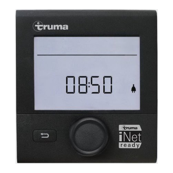
Page 2: Display And Control Elements
Display and control elements (Carrera only) Depending on the specification of your motorhome, the Truma CP-Plus controller may be fitted to control the operation of the Truma Combi appliance. Safety instructions • The device may only be operated if it is in perfect working order. -
Page 3: Back Button
Turn to the left (-) Switch on / return to setting level • Menu is paged from right to left. • Press the control knob / push button for longer than 3 seconds or the • Reduce values. • Back button. Clicking The display shows the setting level. - Page 4 TR U M A D I G ITAL TI MER CON TR OL Heater d = boost * (Targeted, fast heating of the content of the Settable temperature range 5 - 30 °C (1 °C boiler [boiler priority]. The water temperature steps) is kept at the higher level [around 62 °C] –...
-
Page 5: Select Fan Level
Special aspects in the mixed mode Interruption of the power supply 230 V Combi Gas The heater automatically switches to the gas mode. As soon as the 230 V power supply is reconnected, the heater automatically switches back to the mixed mode. Malfunction in the combustion process (e.g. -
Page 6: Operating Mode Description
TR U M A D I G ITAL TI MER CON TR OL Symbol Operating mode Description – Fan is switched off Circulating air, if no device is in operation. 9 speed levels can Vent be selected. Low fan level High fan level (only Combi Gas) Fast heating of the room. -
Page 7: Switch Lighting On/Off
Select power type Deactivate the timer (OFF) • Click to change to the setting level. • Click to change to the setting level. • Use the control knob / push button to select • Use the control knob / push button to the power type. -
Page 8: Service Menu
TR U M A D I G ITAL TI MER CON TR OL Service menu Warning Query the index status of a In the event of a warning, a warning symbol connected device appears to indicate that an operating parameter has reached an undefined status. In this case, the affected device continues to run. -
Page 9: Maintenance
Malfunctions In the case of a malfunction, the control panel immediately jumps to the menu level “malfunction” and shows the error code of the malfunction: Cause remedied / return to setting level • Click the control knob / push button. •... - Page 10 • Use propane (Butane is unsuitable cylinder for heating, especially at tempera- tures below 10 • Room temperature sensor or • Please contact the Truma Service cable faulty • Potential under-voltage battery • Charge battery voltage too low <10.4V • Heating element for FrostControl •...
-
Page 11: Equipment Specification
Truma Combination Boiler be made in specification or operating instructions to the equipment described in The Truma Combination Boiler has been this section after the time of going to press. designed to run on gas or electric power and Every care is taken to ensure that the... -
Page 12: Function Description
Truma Combination boiler to prioritize the Function description electric power source over your gas, which all conserve your gas supply. The liquid gas heater ‘Truma Combi’ is a warm-air heater with integrated hot water boiler (10 litre volume). The burner operates Truma Combi 4E fan-supported, which ensures trouble-free function even when on the move. -
Page 13: Important Operating Notes
Truma parts and failure hoses must always be used if the equipment is to follow the installation and operating operated during the winter. instructions will cancel the warranty and Pressure regulating equipment and hoses indemnify Truma from any liability claims. It also... -
Page 14: Room Thermostat
(i) is located in the all users (e.g. on the wardrobe door)! vehicle. The location of the sensor is Ask Truma to send you stickers, if necessary. determined individually by the vehicle manufacturer, depending on the vehicle type;... -
Page 15: Winter Operation
Winter operation Heating with drained water system Set the rotary switch to the operational setting Heating with water temperature ‘d’. Turn the rotary switch (a) to the desired monitoring thermostat setting (1 – 5). The green LED (b) Set the rotary switch to the operational setting for operation is lit and simultaneously indicates ‘e’. - Page 16 Filling the water heater Maintenance Check if the rotary switch for the drain valve Only original Truma parts may be used for (FrostControl) is set to ‘Operation’, meaning maintenance and repair work! that it is parallel to the water connection The water container used is made of stainless and engaged.
-
Page 17: Technical Data
(automatic output levels) in the blown air system. Gas operation Customers should seek the advice of Truma or Combi 4 E: 2000 / 4000 W their Dealer on how to do this. Electrical operation... -
Page 18: Dometic Absorption Refrigerator
D O M ET IC ABSORP TIO N REF RI GE R AT OR Dometic absorption refrigerator Limitation of liability All information and guidance in these operating Guide to these operating instructions instructions were prepared after taking into Before you start using the refrigerator,please consideration the applicable standards and read the operating instructions carefully. -
Page 19: Energy Saving Tips
Safety instructions Note: Refrigerators manufactured by Dometic GmbH are free of CFC/HCFC Application according to regulations and HFC. Ammonia (a natural compound This refrigerator is designed for installation of hydrogen and nitrogen) is used in the in recreation vehicles such as caravans cooling unit as a coolant. -
Page 20: Information On Coolant
D OM ET IC AB SOR PTI ON REF RI GE R AT OR Safety instructions when WARNING: Never open the absorber storing foodstuffs cooling unit! It is under high pressure. There is a danger of injury. Instructions for storing food in a refrigerator: Information on coolant No refrigerator of any kind can improve the... - Page 21 2. Product Number 3. Serial Number 4. Electrical rating details 5. Gas pressure Note: Dometic refrigerators are equipped for a connection pressure of 30 mbar. For connection to a 50 mbar gas system, use Truma VDR 50/30 medium pressure controller.
- Page 22 D OM ET IC AB SOR PTI ON REF RI GE R AT OR Description of refrigerator 1. Operating controls 2. Door locking button 3. Freezer compartment (removable) 4. Insertable grid shelf (available as option, to be used when freezer compartment is removed) 5.
-
Page 23: Refrigerator Operation
Refrigerator operation • The gas burner must be inspected and cleaned as necessary at least once a year. The refrigerator is equipped to operate on When using liquefied petroleum gas (tank three power modes: or refill cylinders) the maintenance interval is reduced to half-yearly or quarterly. - Page 24 D OM ET IC AB SOR PTI ON REF RI GE R AT OR Manual energy selection / Electrical operation automatic ignition (RM 8xx1) MES To start the refrigerator, press button (1) for 2 seconds. The refrigerator starts with the last selected type of energy.
- Page 25 Setting of cooling compartment temperature Battery compartment Fig. 21 Load the battery compartment with batteries (8 x AA 1.5 V) before operating the refrigerator. Fig. 18 Select the desired cooling compartment All operating modes can be selected while the temperature by pressing button (6) . on-board 12 V DC power supply is active.
-
Page 26: Door Locking
D OM ET IC AB SOR PTI ON REF RI GE R AT OR Mechanical door lock press Open the door by pressing the locking button Opening battery compartment Fig. 22 and pull open. Shut the door again by pushing it to close. - Page 27 Lighting Once the freezer compartment is removed, an additional storage rack (3.) may be installed. If the door is open for more than 2 minutes, The storage rack is a piece of extra equipment the sensor-controlled interior lighting is and may be obtained by Dometic. automatically cut off (except for models with battery igniter).
-
Page 28: Refrigerator Compartments
D OM ET IC AB SOR PTI ON REF RI GE R AT OR Storing food and making When ambient temperatures are lower than +10°C and the refrigerator is exposed to these ice cubes temperatures for extended periods of time, an Storing products in the cooling even regulation of freezer temperature cannot compartment... -
Page 29: Shutting Off The Refrigerator
• Release the locking mechanism of the door lock by pushing it and shift it to the front. If the door is shut in this position, a small gap is nevertheless kept open to prevent formation of mildew. • If the refrigerator is to be taken out of service for an extended period of time, close the onboard shut-off valve and the cylinder valve. -
Page 30: Troubleshooting
TR OU BLESHOO TI N G Troubleshooting Failure: The refrigerator does not cool sufficiently. Possible cause Action you can take Inadequate ventilation to the unit Check that the ventilation grilles are not covered Thermostat setting is too low Set thermostat to a higher level The condenser is heavily frosted Check that the refrigerator door closes properly... -
Page 31: Status Indicators
Failure: The refrigerator does not cool in 230 V operation. Possible cause Action you can take On-board fuse defective Fit new fuse Vehicle not connected to mains supply volt- Make a connection to a mains power supply AES: Gas operation despite connection to the Appliance switches to gas operation due to mains supply voltage? insufficient mains supply voltage (automatically... - Page 32 Operation with on-board 12 v power supply Indicator Fault Remedy (2) and (8) 230 V mode: Check mains power connection, mains voltage, "230V" not avail- fuse flashing and acous- able or voltage too tic signal 20s (4) and (8) 12 V mode: Check 12V connection, on-board battery, fuse "12V"...
-
Page 33: Waeco Fridge
WA E CO FR IDGE Operation with batteries (internal power supply) Indicator Fault Remedy (3) and (8) Flame not ignited Check gas supply (gas bottle, gas valve) flashing brightly Press the (8) button after clearing the fault (3) and (7) Burner defective Check burner, burner nozzles, if necessary con- or cooling unit... -
Page 34: Defrosting The Refrigerator
WAEC O F RIDG E Ensure that the objects placed in the Observe the following when using refrigerator are suitable for cooling to the the refrigerator: selected temperature. • Never re-freeze products which have started defrosting or have been defrosted, but To switch the refrigerator on: consume them as soon as possible. - Page 35 Replacing the interior light Note: The Waeco fridge has an optimum If the interior light in the refrigerator is faulty, ambient temperature range of +16 c to you can change the bulb (12 V, 3 W). c. Outside this range the efficiency of the unit may be affected to the point where •...
- Page 36 WAEC O FRID GE 9. Cleaning and care No. of Fault Possible cause Do not use abrasive cleaning agents or hard flashes objects during cleaning as these can damage Supply The supply voltage the refrigerator. Never use hard or pointed voltage is outside of the tools to remove ice or to loosen objects which...
- Page 37 Interior temperature too low in control level ‘1’ Fault Possible cause Remedy Compressor runs constantly Faulty thermostat Change the thermostat Compressor runs for a Large quantities have long time been frozen in the freezer compartment Compressor does not run (battery connection) = 0 V There is an interruption in Establish a connection...
- Page 38 T R OU B LES HO OTIN G Compressor is not running (connected to AC supply) Fault Possible cause Remedy No voltage Interruption in the Establish a connection supply cable Main switch faulty Replace the main switch (if installed) Additional supply line fuse Replace the supply line fuse has blown (if installed) Voltage is present but the...
-
Page 39: Spinflo Oven
S P IN FL O O V E N Spinflo oven in and hold. It is necessary to hold the knob depressed after the burner has ignited or approximately 10-15 seconds, to allow the WARNING: Before using the appliances thermocouple probe to reach temperature, for the first time, remove all accessories and before releasing the knob. - Page 40 S P INFLO OVEN Using the hotplate 2. To light: Open door, push in the control knob and turn to full rate - see Fig 2. Ensure the electricity is switched on. Hold alighted match or taper to the burner The hotplate control is numbered from 1 to 6.
- Page 41 Fast toasting - trivet in high position 4. Place the oven shelf in the required position Grilling sausages - trivet in high position and close the door. Set control knob to Grilling steak/bacon - trivet in high position approximately gas mark 5 and heat the Grilling chops, etc.
-
Page 42: Cooking Guidelines
S M EV MI N I G RI LL Cooking guidelines Smev mini grill Use the appliance only in a well See user instructions. ventilated space. Do’s and Don’ts The ventilation openings must remain open Do read the user instructions carefully before when the appliances are operating. - Page 43 S ME V H OT P LAT E S Smev hotplates WARNING: If ignition is unsuccessful, Use the appliance only in a well repeat operation from beginning; if ventilated space. necessary. have the appliance checked if a gas and/or electricity failure in the appliance. To use If appliance absolutely does not work, close 1.
-
Page 44: Cleaning Instructions
S M EV HOTPL ATES Ignition of the appliance LEAKS 1. Manual ignltion hotplate If a smell of gas becomes apparent, the a. Push in control knob, slightly turn to ignition supply should be turned off at the cylinder position (big flame). IMMEDIATELY. -
Page 45: Precautions To Avoid Possible Exposure To Excessive Microwave Energy
MICROWAV E Microwave oven general Important safety guidance user instructions Always refer to the microwave operating WARNING: To prevent fire, burns, instructions supplied with the vehicle electric shock and other warnings. Listed below are, as with all appliances, certain Precautions to avoid possible exposure to rules to follow and safeguards to assure high excessive microwave energy performance from this oven:... - Page 46 M IC R O WAVE 10. Do not pop popcorn longer than the To reduce the risk of injury to persons: manufacturer’s directions. (Popping time a. Do not overheat the liquid. is generally below 3minutes). Longer b. Stir the Iiquid both before and halfway cooking does not yield more popped through heating it.
-
Page 47: Thetford Cassette Toilet
THETFO RD CA S S E T T E T OILE T 8. The oven should be cleaned regularly and any food deposits removed; 9. Failure to maintain the oven in a clean condition could lead to deterioration of the surface that could adversely affect the life of the appliance and possibly result in a hazardous situation. -
Page 48: Operation
T HET FO RD CASSETTE TOI LET 11. C-200 CW only: After use, open valve blade (if still closed) and flush, lift the flush handle and press it down (fig. 11). After flushing, close the blade by turning the blade handle. 11a. - Page 49 Leave the blade of the holding tank open. Note: Only depress the vent button when Do not replace cap on the pour out spout, to pour out spout is pointed downwards. ventilate the holding tank. (Also grease the seal Rinse the holding tank with clean water. For of the pour out spout cap.) preparing for use again, see steps 1 to 7.
- Page 50 T HET FORD C 260 AN D C260 S C A S S E T T E T OIL E T not apply or has expired, a nominal charge will be made. Any transport costs are for the account of the owner. 6.
-
Page 51: Control Panel
onto the emptying spout and turn back to its original position. Note: The Emptying Spout Measuring Cap is supplied in the same packaging as the Thetford user manual. WARNING: Never add toilet fluid directly via the blade or the toilet bowl as this could damage the lip seal of the Waste Holding Tank. - Page 52 TH ET FO R D C2 60 AN D C 260S C A SS E T T E T OILE T 12. The toilet may be used with the blade access door located outside the vehicle, pull open or closed. To open the blade, slide the safety catch upwards and remove the the blade handle under the toilet bowl Waste Holding Tank.
- Page 53 20. Waste Pump-Out System: When activating • Clean seat and lid The seat and lid can easily the control panel this feature automatically be removed: Lift the seat and lid assembly lights up. When the Waste Holding Tank and pull the round pins (inside the assembly) Level Indicator illuminates, press the outwards from the pin holes.
- Page 54 T H ET FOR D C26 0 AN D C 260 S CA S S E T T E T OILE T This will ensure that the seals remain flexible instructions for cleaning and maintenance. To and in good condition. If the toilet is not to be allow the Waste Holding Tank to dry, do not used for any length of time, it is important to place the cap back on the emptying spout...
-
Page 55: Roof Lights
WINDO W S / BL IN DS Windows Care instructions: Clean the blind only with a damp sponge. Clean on a regular basis to avoid dirt particle build up as this can damage the blind material. Use only water or with mild suds or a vacuum cleaner. -
Page 56: Midi Heki Roof-Light
M INI HEKI RO OF L I G HT Blind and Flyscreen In order to avoid material fatigue, do not leave the flynet closed for a long time. Midi Heki Roof-light The blind and flyscreen operate Independently of each other and are engaged by connecting to each other and sliding. -
Page 57: Bunk Bed Safety
SEAT SW IV EL / B U N K BE D S A F E T Y / ROOF RACK / O MN IST E P Care instructions: WARNING: Care shall be taken against • Please clean the acrylic panes with the the risk of fall out when the upper bunks are Seitz Acrylic Cleaner. -
Page 58: Omnistor Awning
OM NIS T OR AW N IN G footboard and the arms (with screwdriver 2. Introduce the crank arm into the and wrench S10). bayonet joint. • Slide out the footboard. • Reinstall the front plate. Current drawn • Working current: 5 A •... - Page 59 4. Unroll till 1 m max. Then put out the support arms before further unrolling Note: Never put out the support arms that high, that the fabric jams between the arms 5. Slide the support arms out of the and the box. front profile.
- Page 60 OM NIS TOR AWN I N G 8. Install the tension rafter (for 3.75 m awning). 9. When raining, lower one side of the awning in such a way that the water can run down the fabric. Prevent the fabric from flying up by a sudden wind blow by using the hold down kit (optional).
- Page 61 STAT U S 550 A N T EN NA Status 550 Digital antenna system Travelling Do not travel: • with the antenna raised • with the antenna set for vertical signals To reduce the possibility of damage when travelling, point the antenna backwards. The RED SPOT on the bottom of the mast indicates the front of the Antenna.
-
Page 62: Coaxial Connections
S TATU S 5 50 AN TEN N A Short Hook up - Test 1 This test isolates the wiring from the amplifier through to your TV/Radio points. Unplug the coaxial plugs from the 'TV' sockets of the amplifier and using your TV fly lead with convertor 1 supplied. - Page 63 Signal Symptom Action No picture or sound, TV freez- Very poor ing, severe pixila- tion, break up and Check the amplifier gain is set to maximum picture drop out (rotate clockwise). Check antenna alignment which must be directed at the transmitter. Moderate pixilation Ensure the antennas polarity is correct, whether Poor...
-
Page 64: Avtex Dvd
AV T EX TV A N D AN TEN N A Avtex TV and antenna the unit is ON, an LED will illuminate on the front of the unit. Depending on the specification of your Care of laminate tops, tables, motorhome, a supplied television (or furniture and doors telelvisions) may be present. -
Page 65: Tv Inlet
S HOW ER / TV IN L ET / C O LOU R R E FE R E NCE Shower A short co-ax lead featuring a screw on co-ax connection will be present behind the Blue When using the shower, always ensure that mains inlet connector. - Page 66 EQ U IP M EN T DETAI L S...
Need help?
Do you have a question about the DIGITAL TIMER CONTROL and is the answer not in the manual?
Questions and answers