Table of Contents
Advertisement
Available languages
Available languages
Solar Dual Battery Charge Controller
Solar Dual Battery Charge
SDC12 & SDC
& SDC25
Operating instructions
Operating instructions
Installation instructions
instructions
To be kept in the vehicle!
To be kept in the vehicle!
Bruksanvisning
Bruksanvisning
Skall medföras i fordonet!
Skall medföras i fordonet!
Page 3
Page 16
Sida 17
Sida 29
Advertisement
Chapters
Table of Contents

Related Manuals for Truma SDC12


Summary of Contents for Truma SDC12
- Page 1 Solar Dual Battery Charge Solar Dual Battery Charge Controller SDC12 & SDC & SDC25 Page 3 Operating instructions Operating instructions Installation instructions instructions Page 16 To be kept in the vehicle! To be kept in the vehicle! Bruksanvisning Bruksanvisning Sida 17 Skall medföras i fordonet!
-
Page 2: Kopplingsschema
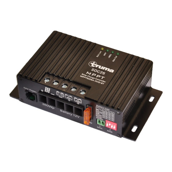
Fig. A Wiring Diagram Note: The connection plan shows the maximum terminal assignment for operation of all existing functions of the solar controller. The minimum terminal assignment consists of the solar panel inputs ("+" and "-") and the connections of the main battery. Always connect the fuses as close as possible to the batteries (cable protection!). -
Page 4: Table Of Contents
Solar Dual Battery Charger Controller SDC12 & SDC25 Installation instructions Table of contents Safety instructions .................. 13 Symbols used................ 04 Delivery scope ..................14 Assembly ....................14 Connection ....................14 Operating instructions Connection Sequence .................. 15 Wiring diagram ........ -
Page 5: Safety Instructions
12vDC lead accumulators comprising 6 single cells (for example leisure battery) with a capacity of 80 – 110** Ah (SDC12) or 80 – 200** Ah (SDC25). The device was This device has not been designed for use by people developed for connection to solar modules. -
Page 6: Improper Use
Batteries should be fully charged before and after being used. Main Fuse 20amp SDC12 Main Fuse 20amp SDC12 – 40amp SDC25 – In the case of longer standstills (without sunshine), disconnect the battery and charge separately for 24 hours at... -
Page 7: Function
Function Charging process The device is a MPPT, or maximum power point tracker, an The device has an electronic reverse input voltage, reverse electronic DC to DC converter that optimises the match current and solar short-circuit protection. The charging current between the solar panels (PV panels) and battery. -
Page 8: Partially Discharged Batteries
Battery Type Selection Partially Discharged Batteries (only for AGM and liquid electrolyte battery type) Operation In contrast to other battery types, batteries on lead basis do On the Charge Controller bottom face, the bottom face, the battery type DIP not have any harmful memory effect. Consequently: In switches and battery type table can be found. -
Page 9: Charging Parameters
Charging Parameters Battery Type Boost Charging Voltage Float Charging Voltage Default Temperature 14.3 volts (3 – 10 hours) 13.8 volts 20°C Lead Acid 14.4 volts (1.5 – 6 hours) 13.45 volts 20°C 14.7 volts (1.5 – 5 hours) 13.5 volts 20°C LiFePO4 14.4volts (0.5 –... -
Page 10: Function Display / Status
Function display / troubleshooting On the Charge Controller front face, status LED’s are Display Status positioned. The following table details the indicating condition of each LED. Batt Low - • Main Main battery voltage is below illuminated 10.5 volts. • Disch ischarged battery. -
Page 11: Technical Data
Technical data Main Battery SDC12 SDC25 Description SDC12 SDC25 Charging/Floating/Load 0 – 12 A 0 – 25 A Capacity of Solar Panel 50 - 165 Wp 50 - 350 Wp Current (recommended / max.) Reset Voltage (30 sec) 12.7v 12.7v... -
Page 12: Manufacturer's Warranty (Uk Eu)
Manufacturer. As the Manufacturer of the unit, Truma undertakes a warranty towards the Consumer that covers any material and/or No further-reaching claims shall be permitted, especially manufacturing defects of the unit. -
Page 13: Installation Instructions
The warranty must be claimed with an authorised service partner mounting and installing. or at the Truma Service Centre. All the relevant addresses and phone numbers can be found at www.truma.com, in the The device was developed for the connection of solar mod- “Service”... -
Page 14: Delivery Scope
(approx. 18 V). with an external venting system. The gel and AGM batteries do Just ask your dealer for the Truma Cable Set Expansion. Just ask your dealer for the Truma Cable Set Expansion. -
Page 15: Connection Sequence
If used, the output for starter battery II will be working with • Connection sequence reduced voltage and charging current rates. Thus, the main solar power will be supplied to main battery being more suitable. Main Battery “MAIN I” (must be connected): However, the vehicles starter battery II will be kept in a •... -
Page 16: Commissioning
(observe connection sequence). capacity, and energy (V, A, W, Ah, Wh) This information can also be displayed through the • Truma iNetX Pro Control Panel coming in Summer The right to effect technical modifications is reserved! 2021. Disposal Safety Mode: Neither the regulator nor the solar panel may be disposed of with domestic waste. -
Page 17: Avsedd Användning
Solar Dual Battery Charger Controller SDC12 & SDC25 Installationsinstruktioner Innehållsförteckning Säkerhetsanvisningar ..................26 Symboler som används ............17 Leveransomfattning ..................27 församling ..................... 27 samband ......................27 Bruksanvisning Anslutningssekvens ..................... 28 Kopplingsschema ......................03 ordlista ................ -
Page 18: Säkerhetsanvisningar
Täck solmoduler med t.ex. kartong, innan du monterar och installerar eller kopplar bort. Fig. 1: Enhetselement använda Huvudsäkring 20amp SDC12 – 40amp SDC25 Denna enhet har inte utformats för användning av personer DIP-brytare för val av batterityp (inklusive barn) som har begränsade fysiska, sensoriska eller Solcellsterminaler –... -
Page 19: Funktion
funktion Laddningsprocess Enheten är en MPPT, eller maximal strömpunktspårare, en elektronisk DC till DC-omvandlaresomoptimerarmatchningen Enheten har en elektronisk omvänd ingångsspänning, mellan solpanelerna (solcellspaneler) och batteriet. Detta omvänd ström solkortslutningsskydd. möjliggör hög prestanda i kombination med en lätt vikt och små Laddningsströmmen släpps endast (se "laddningsschema") dimensioner. -
Page 20: Delvis Urladdade Batterier
Delvis urladdade batterier Val av batterityp (endast för AGM- och flytande elektrolytbatterityp) operation Till skillnad från andra batterityper har blybatterier ingen På laddningskontrollens undersida finns DIP På laddningskontrollens undersida finns DIP-omkopplare av skadlig minneseffekt. Följaktligen: I tveksamma fall måste batterityp och batterityp. Bekräfta vilken typ av batteri som batterityp och batterityp. -
Page 21: Laddningsparametrar
Laddningsparametrar Batterityp Öka laddningsspänningen Flytladdningsspänning Standardtemperatur 14.3 volts (3 – 10 Timmar) 13.8 volts 20°C Lead Acid 14.4 volts (1.5 – 6 Timmar) 13.45 volts 20°C 14.7 volts (1.5 – 5 Timmar) 13.5 volts 20°C LiFePO4 14.4volts (0.5 – 3 Timmar) 13.8 volts 20°C Laddningsprocess... -
Page 22: Funktionsdisplay / Status
visa status status – Batt Low - Huvudbatterispänningen är Huvudbatterispänningen är upplyst under 10,5 volt. under 10,5 volt. – Urladdat batteri. Urladdat batteri. – Otillräcklig batterianslutning Otillräcklig batterianslutning – Misslyckad matningssäkring Misslyckad matningssäkring – MPP - upplyst CC Laddning – MPP-kort blinkande CC redo att laddas –... -
Page 23: Tekniska Data
Tekniska data Startbatteri SDC12 SDC25 beskrivning SDC12 SDC25 Laddning/flytande/lastström 0 – 12 A 0 – 25 A Solpanels kapacitet 50 - 165 50 - 350 (rekommenderas / Återställ spänning (30 sek) 12.7v 12.7v max.) Begränsning av 14.8v 14.8v Nuvarande solpanel 0 - 10 A 0 - 21.0 A... -
Page 24: Tillverkarens Garanti (Uk Eu)
1. Tillverkarens garanti eller tillverkaren ådrar sig. Som tillverkare av enheten åtar sig Truma en garanti gentemot Inga ytterligare anspråk ska tillåtas, särskilt inte konsumenten som täcker alla material- och/eller tillverkningsfel dammålderskrav som lämnas in av konsumenten eller tredje i enheten. -
Page 25: Säkerhetsanvisningar
"Service". Enheten utvecklades för anslutning av solmod- ules. Använd endast lämpliga moduler, t.ex. Truma SM 25, 40, För att säkerställa ett smidigt förfarande bör vi vara 65, 80, 100, 120, 150 eller 180. Observera de maximala tacksamma om du kunde ha följande uppgifter klara innan spännings- och effektdragningsvärdena. -
Page 26: Leveransomfattning
(ca 18 V). moduler med samma typiska spänningsvärden (ca 18 V). monteringsregler. Fråga bara din återförsäljare om Truma Cable Set Fråga bara din återförsäljare om Truma Cable Set Expansion. Fäst enheten med fyra skruvar (diameter 4 mm – inte försänkta huvudskruvar). -
Page 27: Anslutningssekvens
Denna kabel kan vara längre. Vid icke-användning lämnas denna terminal fri. Anslutningssekvens Om den används kommer utgången för startbatteri II att fungera reducerad spänning 1. Huvudbatteriet "MAIN I" (måste anslutas): laddningsströmhastigheter. Således kommer huvudsakliga solenergin att levereras till huvudbatteriet Anslut laddningsregulatorns batterikontakter •... - Page 28 • Batterispänning, laddningsström, laddningskapacitet, lagrad kapacitet och energi (V, Rätten att genomföra tekniska ändringar är förbehållen! A, W, Ah, Wh) Denna information kan också visas via Truma iNetX • förfogande Pro Kontrollpanelen som kommer sommaren 2021. Varken regulatorn eller solpanelen får...
- Page 29 Should problems occur, please contact the Truma Service Centre or one of our authorised service partners see www.truma.com. In order to avoid delays, please have the unit model and serial number ready (see type plate on reverse face of solar charge controller).
Need help?
Do you have a question about the SDC12 and is the answer not in the manual?
Questions and answers
how do i clear all lights flashing on solar panel
All lights flashing on the Truma SDC12 solar panel unit indicate the battery selection is wrong. To clear this, check and correct the battery type selection setting on the controller.
This answer is automatically generated
Hi can the truma sdc12 support charging a lithium battery? Regards Dan
The Truma SDC12 is designed for batteries with gel, AGM, or liquid electrolyte. There is no mention of support for lithium batteries. Therefore, it does not appear to support charging a lithium battery.
This answer is automatically generated