Table of Contents
Advertisement
Advertisement
Table of Contents
Troubleshooting

Related Manuals for ZyXEL Communications UAG2100


Summary of Contents for ZyXEL Communications UAG2100
- Page 1 UAG2100 Unified Access Gateway Version 4.00 Edition 1, 08/2014 Quick Start Guide User’s Guide Default Login Details LAN IP Address http://172.16.0.1 (LAN1) http://172.17.0.1 (LAN2) User Name www.zyxel.com admin Password 1234 Copyright © 2014 ZyXEL Communications Corporation...
- Page 2 The CLI Reference Guide explains how to use the Command-Line Interface (CLI) to configure the UAG. Note: It is recommended you use the Web Configurator to configure the UAG. • Web Configurator Online Help Click the help icon in any screen for help in configuring that screen and supplementary information. UAG2100 User’s Guide...
-
Page 3: Table Of Contents
Firewall ..............................232 Billing ..............................246 Printer Manager ............................262 Free Time ..............................269 SMS ..............................273 Bandwidth Management ........................275 User/Group ............................285 AP Profile ..............................299 Addresses .............................314 Services ..............................319 Schedules .............................324 AAA Server ............................328 Authentication Method ..........................332 Certificates ............................335 ISP Accounts ............................351 UAG2100 User’s Guide... - Page 4 Contents Overview System ..............................354 Log and Report .............................395 File Manager ............................410 Diagnostics ............................421 Packet Flow Explore ..........................429 Reboot ..............................437 Shutdown ..............................438 Troubleshooting ............................439 UAG2100 User’s Guide...
-
Page 5: Table Of Contents
Installation Setup Wizard ........................44 4.1 Installation Setup Wizard Screens ....................44 4.1.1 Internet Access Setup - WAN Interface ..................44 4.1.2 Internet Access: Ethernet .......................45 4.1.3 Internet Access: PPPoE ......................46 4.1.4 Internet Access: PPTP ......................48 4.1.5 Internet Access - Finish ......................49 UAG2100 User’s Guide... - Page 6 7.10 The USB Storage Screen ........................81 7.11 The Dynamic Guest Screen ......................82 7.12 The AP List Screen ........................84 7.12.1 Station Count of AP ......................85 7.13 The Radio List Screen ........................86 7.13.1 AP Mode Radio Information ....................88 7.14 The Station List Screen ........................89 UAG2100 User’s Guide...
- Page 7 10.4.2 PPP Interface Add or Edit ....................122 10.5 VLAN Interfaces ...........................126 10.5.1 VLAN Interface Summary Screen ..................127 10.5.2 VLAN Interface Add/Edit .....................128 10.6 Bridge Interfaces ..........................133 10.6.1 Bridge Interface Summary ....................135 10.6.2 Bridge Interface Add/Edit ....................136 10.7 Virtual Interfaces ...........................140 UAG2100 User’s Guide...
- Page 8 14.1.1 What You Can Do in this Chapter ..................168 14.1.2 What You Need to Know ......................168 14.2 The DDNS Screen ........................169 14.2.1 The Dynamic DNS Add/Edit Screen ..................170 Chapter 15 NAT..............................173 15.1 NAT Overview ..........................173 15.1.1 What You Can Do in this Chapter ..................173 UAG2100 User’s Guide...
- Page 9 19.1.1 What You Can Do in this Chapter ..................193 19.1.2 What You Need to Know ......................193 19.1.3 Before You Begin .........................194 19.2 The ALG Screen ...........................194 Chapter 20 UPnP ..............................195 20.1 Overview ............................195 20.2 What You Need to Know .......................195 20.2.1 NAT Traversal ........................195 UAG2100 User’s Guide...
- Page 10 24.2.1 Creating/Editing an Authentication Policy ................220 24.2.2 User-aware Access Control Example ..................221 24.3 Walled Garden Screen .........................227 24.3.1 Adding/Editing a Walled Garden URL ................228 24.3.2 Walled Garden Login Example ....................228 24.4 Advertisement Screen ........................229 24.4.1 Adding/Editing an Advertisement URL ................230 UAG2100 User’s Guide...
- Page 11 27.3 The Printout Configuration Screen ....................264 27.3.1 Reports Overview ........................265 27.3.2 Key Combinations .......................265 27.3.3 Daily Account Summary ......................266 27.3.4 Monthly Account Summary ....................266 27.3.5 Account Report Notes ......................267 27.3.6 System Status ........................267 Chapter 28 Free Time ............................269 UAG2100 User’s Guide...
- Page 12 32.1.1 What You Can Do in this Chapter ..................299 32.1.2 What You Need To Know .....................299 32.2 Radio Screen ..........................300 32.2.1 Add/Edit Radio Profile ......................302 32.3 SSID Screen ..........................305 32.3.1 SSID List ..........................305 32.3.2 Add/Edit SSID Profile ......................307 32.3.3 Security List .........................308 UAG2100 User’s Guide...
- Page 13 36.1 Overview ............................328 36.1.1 RADIUS Server ........................328 36.1.2 What You Can Do in this Chapter ..................328 36.1.3 What You Need To Know .....................328 36.2 RADIUS Server Summary ......................329 36.2.1 Adding a RADIUS Server ....................329 Chapter 37 Authentication Method........................332 UAG2100 User’s Guide...
- Page 14 40.4.2 Time Server Synchronization ....................359 40.5 Console Port Speed ........................360 40.6 DNS Overview ..........................361 40.6.1 DNS Server Address Assignment ..................361 40.6.2 Configuring the DNS Screen ....................361 40.6.3 Address Record ........................363 40.6.4 PTR Record .........................363 40.6.5 Adding an Address/PTR Record ..................363 UAG2100 User’s Guide...
- Page 15 41.3 Log Settings Screens ........................397 41.3.1 Log Settings Summary ......................398 41.3.2 Edit System Log Settings ....................399 41.3.3 Edit Log on USB Storage Setting ..................402 41.3.4 Edit Remote Server Log Settings ..................404 41.3.5 Log Category Settings Screen .....................406 Chapter 42 File Manager............................410 UAG2100 User’s Guide...
- Page 16 45.2 The Reboot Screen ........................437 Chapter 46 Shutdown............................438 46.1 Overview ............................438 46.1.1 What You Need To Know .....................438 46.2 The Shutdown Screen ........................438 Chapter 47 Troubleshooting..........................439 47.1 Resetting the UAG ........................445 47.2 Getting More Troubleshooting Help ....................446 UAG2100 User’s Guide...
- Page 17 Table of Contents Appendix A Customer Support ......................447 Appendix B Legal Information......................453 Index ..............................459 UAG2100 User’s Guide...
-
Page 18: Introduction
The default configurations for zones, interfaces, and ports are as follows. References to interfaces may be generic rather than the specific name used in your model. For example, this guide may use “the WAN interface” rather than “P1”. UAG2100 User’s Guide... -
Page 19: Management Overview
You can manage the UAG in the following ways. Web Configurator The Web Configurator allows easy UAG setup and management using an Internet browser. This User’s Guide provides information about the Web Configurator. Figure 2 Managing the UAG: Web Configurator UAG2100 User’s Guide... -
Page 20: Web Configurator
The Login screen appears. Type the user name (default: “admin”) and password (default: “1234”). Click Login. If you logged in using the default user name and password, the Update Admin Info screen appears. Otherwise, the dashboard appears. UAG2100 User’s Guide... -
Page 21: Web Configurator Screens Overview
See the Command Reference Guide for information about the commands. Click this to open a popup window that displays the CLI commands sent by the Web Configurator to the UAG. About Click About to display basic information about the UAG. UAG2100 User’s Guide... - Page 22 This shows the date (yyyy-mm-dd) and time (hh:mm:ss) when the firmware is released. Click this to close the screen. Site Map Click Site MAP to see an overview of links to the Web Configurator screens. Click a screen’s link to go to that screen. Figure 5 Site Map UAG2100 User’s Guide...
- Page 23 Click Cancel to close the screen. CLI Messages Click CLI to look at the CLI commands sent by the Web Configurator. Open the pop-up window and then click some menus in the web configurator to dislay the corresponding commands. UAG2100 User’s Guide...
-
Page 24: Navigation Panel
The dashboard displays general device information, system status, system resource usage, licensed service status, and interface status in widgets that you can re-arrange to suit your needs. See Chapter 6 on page 58 for details on the dashboard. UAG2100 User’s Guide... -
Page 25: Monitor Menu
Display the UAG’s dynamic guest account log messages. Configuration Menu Use the configuration menu screens to configure the UAG’s features. Table 6 Configuration Menu Screens Summary FOLDER OR LINK TAB FUNCTION Quick Setup Quickly configure WAN interfaces. Licensing UAG2100 User’s Guide... - Page 26 Create walled garden links that display in the login screen. Adverstisement Enable and set advertisement links. Firewall Firewall Create and manage level-3 traffic rules. Session Limit Limit the number of concurrent client NAT/firewall sessions. Billing General Configure the general billing settings, such as the accounting method. UAG2100 User’s Guide...
- Page 27 Service Control Configure HTTP, HTTPS, and general authentication. Login Page Configure how the login and access user screens look. Configure SSH server and SSH service settings. TELNET Configure telnet server settings for the UAG. Configure FTP server settings. UAG2100 User’s Guide...
-
Page 28: Tables And Lists
Click the down arrow next to a column heading for more options about how to display the entries. The options available vary depending on the type of fields in the column. Here are some examples of what you can do: UAG2100 User’s Guide... - Page 29 Figure 12 Moving Columns Use the icons and fields at the bottom of the table to navigate to different pages of entries and control how many entries display at a time. Figure 13 Navigating Pages of Table Entries UAG2100 User’s Guide...
- Page 30 In some lists you can also use the [Shift] or [Ctrl] key to select multiple entries, and then use the arrow button to move them to the other list. UAG2100 User’s Guide...
-
Page 31: Stopping The Uag
Figure 15 Working with Lists 1.5 Stopping the UAG Always use Maintenance > Shutdown > Shutdown or the shutdown command before you turn off the UAG or remove the power. Not doing so can cause the firmware to become corrupt. UAG2100 User’s Guide... -
Page 32: Hardware Installation And Connection
Make sure the screws are fastened well enough to hold the weight of the UAG with the connection cables. Align the holes on the back of the UAG with the screws on the wall. Hang the UAG on the screws. UAG2100 User’s Guide... -
Page 33: Front Panel
Chapter 2 Hardware Installation and Connection Figure 16 Wall Mounting Example 2.2 Front Panel This section introduces the UAG’s front panel. Figure 17 UAG Front Panel UAG2100 User’s Guide... -
Page 34: Front Panel Leds
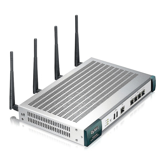
There is no connection on this port. 2.3 Rear Panel The following figure shows the rear panel of the UAG. The rear panel contains a console port, a power switch and a connector for the power receptacle and four antennas. UAG2100 User’s Guide... - Page 35 • No flow control Connect the male 9-pin end of the RS-232 console cable to the console port of the UAG. Connect the female end to a serial port (COM1, COM2 or other COM port) of your computer. UAG2100 User’s Guide...
-
Page 36: Printer Deployment
Section 1.4 on page 20 on how to access the web configurator. Enter your Internet access information to set up a Internet connection. See Chapter 4 on page 44 for detailed information on how to use the setup wizard. UAG2100 User’s Guide... -
Page 37: Allow The Uag To Monitor And Manage The Printer
Go to the Dashboard of the UAG web configurator. Open the DHCP Table to find the IP address that is assigned to the printer’s MAC address. Make sure the IP address is reserved for the printer. Write down the printer’s IP address. UAG2100 User’s Guide... - Page 38 Go to the Configuration > Printer Manager screen. Click Add in the Printer List to create a new entry for your printer. After the printer’s IP address is added to the printer list, select the Enable Printer Manager checkbox and then click Apply. UAG2100 User’s Guide...
-
Page 39: Turn On Web Authentication On The Uag
Apply in the the Configuration > Printer Manager screen. 3.5 Turn on Web Authentication on the UAG With web authentication, users need to log in through a designated web page before they can access the network(s). Go to the Configuration > Web Authentication screen. UAG2100 User’s Guide... - Page 40 Click Add to create a new web authentication policy. The Auth. Policy Add screen displays. Set Authentication to required and select Force User Authentication to redirect all HTTP traffic to the default login page. Click OK to save your changes. UAG2100 User’s Guide...
-
Page 41: Generate A Free Guest Account
Select the Enable Free Time checkbox to turn on this feature. Click Apply. Whenever a user tries to access a web page, he/she will be redirect to the default login page. Click the link on the login page to get a free guest account. UAG2100 User’s Guide... - Page 42 A Welcome screen displays. Select the free time service. Click OK to generate and show the account information on the web page. Now you can use this account to access the Internet through the UAG for free. UAG2100 User’s Guide...
- Page 43 Chapter 3 Printer Deployment UAG2100 User’s Guide...
-
Page 44: Installation Setup Wizard
The screens vary depending on the encapsulation type. Refer to information provided by your ISP to know what to enter in each field. Leave a field blank if you don’t have that information. Note: Enter the Internet access information exactly as your ISP gave it to you. UAG2100 User’s Guide... -
Page 45: Internet Access: Ethernet
This screen is read-only if you set the previous screen’s IP Address Assignment field to Auto. Use this screen to configure your IP address settings. Note: Enter the Internet access information exactly as given to you by your ISP. UAG2100 User’s Guide... -
Page 46: Internet Access: Pppoe
DDNS and the time server. Leave the field as 0.0.0.0 if you do not want to configure DNS servers. 4.1.3 Internet Access: PPPoE Note: Enter the Internet access information exactly as given to you by your ISP. UAG2100 User’s Guide... - Page 47 • Zone: This is the security zone to which this interface and Internet connection will belong. • IP Address: Enter your (static) public IP address. Auto displays if you selected Auto as the IP Address Assignment in the previous screen. UAG2100 User’s Guide...
-
Page 48: Internet Access: Pptp
• CHAP/PAP - Your UAG accepts either CHAP or PAP when requested by the remote node. • CHAP - Your UAG accepts CHAP only. • PAP - Your UAG accepts PAP only. • MSCHAP - Your UAG accepts MSCHAP only. • MSCHAP-V2 - Your UAG accepts MSCHAP-V2 only. UAG2100 User’s Guide... -
Page 49: Internet Access - Finish
0.0.0.0 if you do not want to configure DNS servers. 4.1.5 Internet Access - Finish You have set up your UAG to access the Internet. A screen displays with your settings. If they are not correct, click Back. UAG2100 User’s Guide... -
Page 50: Device Registration
UAG’s serial number and LAN MAC address to register it if you have not already done so. Note: You must be connected to the Internet to register. Use the Registration > Service screen to update your service subscription status. UAG2100 User’s Guide... - Page 51 Chapter 4 Installation Setup Wizard Figure 25 Registration UAG2100 User’s Guide...
-
Page 52: Quick Setup Wizards
5.2 WAN Interface Quick Setup Click WAN Interface in the main Quick Setup screen to open the WAN Interface Quick Setup Wizard Welcome screen. Use these screens to configure an interface to connect to the Internet. Click Next. UAG2100 User’s Guide... -
Page 53: Choose An Ethernet Interface
WAN Type Selection: Select the type of encapsulation this connection is to use. Choose Ethernet when the WAN port is used as a regular Ethernet. Otherwise, choose PPPoE or PPTP for a dial-up connection according to the information from your ISP. UAG2100 User’s Guide... -
Page 54: Configure Wan Ip Settings
Ethernet and set the IP Address Assignment to Auto. If you set the IP Address Assignment to Static and/or select PPTP or PPPoE, enter the Internet access information exactly as your ISP gave it to you. UAG2100 User’s Guide... - Page 55 Type the password associated with the user name above. Use up to 64 ASCII characters except the [] and ?. This field can be blank. Retype to Type your password again for confirmation. Confirm Nailed-Up Select Nailed-Up if you do not want the connection to time out. UAG2100 User’s Guide...
-
Page 56: Quick Setup Interface Wizard: Summary
DNS server (in the order you specify here) to resolve domain names for DDNS and the time server. Back Click Back to return to the previous screen. Next Click Next to continue. 5.2.5 Quick Setup Interface Wizard: Summary This screen displays the WAN interface’s settings. UAG2100 User’s Guide... - Page 57 This field only appears for an Ethernet interface. It displays the IP address of the gateway. Address First DNS Server If the IP Address Assignment is Static, these fields display the DNS server IP address(es). Second DNS Server Close Click Close to exit the wizard. UAG2100 User’s Guide...
-
Page 58: Dashboard
The dashboard displays general device information, system status, system resource usage, licensed service status, and interface status in widgets that you can re-arrange to suit your needs. You can also collapse, refresh, and close individual widgets. UAG2100 User’s Guide... - Page 59 Up Arrow (B) Click this to collapse a widget. It then becomes a down arrow. Click it again to enlarge the widget again. Refresh Time Set the interval for refreshing the information displayed in the widget. Setting (C) UAG2100 User’s Guide...
- Page 60 Click the icon to open the screen where you can configure the UAG’s date and time. DHCP Table Click this to look at the IP addresses currently assigned to the UAG’s DHCP clients and the IP addresses reserved for specific MAC addresses. See Section 6.2.4 on page UAG2100 User’s Guide...
- Page 61 Assignment Static - This interface has a static IP address. DHCP Client - This Ethernet interface gets its IP address from a DHCP server. Dynamic - This PPP interface gets its IP address from a DHCP server. UAG2100 User’s Guide...
- Page 62 This section displays a summary for all connected wireless APs. Click the link to go to the AP information > AP List screen. Online This displays the number of currently connected management APs. Management Offline This displays the number of currently offline managed APs. Management UAG2100 User’s Guide...
-
Page 63: The Cpu Usage Screen
This field displays the destination address (if any) in the packet that generated the log. 6.2.1 The CPU Usage Screen Use this screen to look at a chart of the UAG’s recent CPU usage. To access this screen, click CPU Usage in the dashboard. Figure 34 Dashboard > CPU Usage UAG2100 User’s Guide... -
Page 64: The Memory Usage Screen
Click this to update the information in the window right away. 6.2.3 The Active Sessions Screen Use this screen to look at a chart of the UAG’s recent traffic session usage. To access this screen, click Show Active Sessions in the dashboard. UAG2100 User’s Guide... -
Page 65: The Dhcp Table Screen
Use this screen to look at the IP addresses currently assigned to DHCP clients and the IP addresses reserved for specific MAC addresses. To access this screen, click DHCP Table in System Status in the dashboard. Figure 37 Dashboard > DHCP Table UAG2100 User’s Guide... -
Page 66: The Number Of Login Users Screen
Use this screen to look at a list of the users currently logged into the UAG. Users who close their browsers without logging out are still shown as logged in here. To access this screen, click Number of Login Users in System Status in the dashboard. Figure 38 Dashboard > Number of Login Users UAG2100 User’s Guide... - Page 67 (external user), this field will show its external-group information when you move your mouse over it. If the external user matches two external-group objects, both external-group object names will be shown. Force Logout Click this icon to end a user’s session. UAG2100 User’s Guide...
-
Page 68: Monitor
• Use the Station Info > Station List screen (see Section 7.14 on page 89) to view statistics pertaining to the connected stations (or “wireless clients”). • Use the Printer Status screen (see Section 7.15 on page 90) to view information about the connected statement printers. UAG2100 User’s Guide... -
Page 69: The Port Statistics Screen
Poll Interval and clicking Set Interval. Switch to Click this to display the port statistics as a line graph. Graphic View This field displays the port’s number in the list. Port This field displays the physical port number. UAG2100 User’s Guide... -
Page 70: The Port Statistics Graph Screen
Use this screen to look at a line graph of packet statistics for each physical port. To access this screen, click Port Statistics in the Status screen and then the Switch to Graphic View Button. Figure 40 Monitor > System Status > Port Statistics > Switch to Graphic View UAG2100 User’s Guide... -
Page 71: The Interface Status Screen
7.3 The Interface Status Screen This screen lists all of the UAG’s interfaces and gives packet statistics for them. Click Monitor > System Status > Interface Status to access this screen. Figure 41 Monitor > System Status > Interface Status UAG2100 User’s Guide... - Page 72 Ethernet interfaces. Name This field displays the name of each interface. If there is a Expand icon (plus-sign) next to the name, click this to look at the statistics for virtual interfaces on top of this interface. UAG2100 User’s Guide...
-
Page 73: The Traffic Statistics Screen
You use the Traffic Statistics screen to tell the UAG when to start and when to stop collecting information for these reports. You cannot schedule data collection; you have to start and stop it manually in the Traffic Statistics screen. UAG2100 User’s Guide... - Page 74 This field indicates whether the IP address or user is sending or receiving traffic. RX From- traffic is coming from the IP address or user to the UAG. Tx To - traffic is going from the UAG to the IP address or user. UAG2100 User’s Guide...
-
Page 75: The Session Monitor Screen
7.5 The Session Monitor Screen The Session Monitor screen displays information about all established sessions that pass through the UAG for debugging or statistical analysis. It is not possible to manage sessions in this screen. The following information is displayed. UAG2100 User’s Guide... - Page 76 The User, Service, Source Address, and Destination Address fields display if you view all sessions. Select your desired filter criteria and click the Search button to filter the list of sessions. UAG2100 User’s Guide...
-
Page 77: The Ddns Status Screen
This field displays the length of the active session in seconds. 7.6 The DDNS Status Screen The DDNS Status screen shows the status of the UAG’s DDNS domain names. Click Monitor > System Status > DDNS Status to open the following screen. UAG2100 User’s Guide... -
Page 78: The Ip/Mac Binding Monitor Screen
MAC binding enabled and have ever established a session with the UAG. Devices that have never established a session with the UAG do not display in the list. Figure 45 Monitor > System Status > IP/MAC Binding UAG2100 User’s Guide... -
Page 79: The Login Users Screen
See Chapter 31 on page 285. Type This field displays the way the user logged in to the UAG. IP Address This field displays the IP address of the computer used to log in to the UAG. UAG2100 User’s Guide... -
Page 80: The Upnp Port Status Screen
Internal Client. Protocol This field displays the protocol of the NAT mapping rule (TCP or UDP). Internal Port This field displays the port number on the Internal Client to which the UAG should forward incoming connection requests. UAG2100 User’s Guide... -
Page 81: The Usb Storage Screen
This field displays what file system the USB storage device is formatted with. This field displays Unknown if the file system of the USB storage device is not supported by the UAG, such as NTFS. Speed This field displays the connection speed the USB storage device supports. UAG2100 User’s Guide... -
Page 82: The Dynamic Guest Screen
Use this screen to look at a list of dynamic guest user accounts on the UAG’s local database. To access this screen, click Monitor > System Status > Dynamic Guest. Figure 49 Monitor > System Status > Dynamic Guest UAG2100 User’s Guide... - Page 83 Table 31 Monitor > System Status > Dynamic Guest Icons LABEL DESCRIPTION This guest account is un-used. This guest account is in use and online. This guest account has been used but is offline now. This guest account expired. This guest account has been deleted. UAG2100 User’s Guide...
-
Page 84: The Ap List Screen
UAG last started up. Last Off-line This displays the most recent time the AP went off-line. N/A displays if the AP has either Time not come on-line or gone off-line since the UAG last started up. UAG2100 User’s Guide... -
Page 85: Station Count Of Ap
Use this screen to look at station statistics for the connected AP. To access this screen, select an entry and click the More Information button in the AP List screen. Figure 51 Monitor > Wireless > AP Information > AP List > Station Count of AP UAG2100 User’s Guide... -
Page 86: The Radio List Screen
This displays the model of the AP to which the radio belongs. MAC Address This displays the MAC address of the radio. Radio This indicates the radio number on the AP to which it belongs. OP Mode This indicates the radio’s operating mode, such as AP (access point). UAG2100 User’s Guide... - Page 87 This displays the total number of packets transmitted by the radio. Rx FCS Error This indicates the number of received packet errors accrued by the radio. Count Tx Retry Count This indicates the number of times the radio has attempted to re-transmit packets. UAG2100 User’s Guide...
-
Page 88: Ap Mode Radio Information
24 hours. To access this window, select an entry and click the More Information button in the Radio List screen. Figure 53 Monitor > Wireless > AP Information > Radio List > AP Mode Radio Information UAG2100 User’s Guide... -
Page 89: The Station List Screen
7.14 The Station List Screen Use this screen to view statistics pertaining to the associated stations (or “wireless clients”). Click Monitor > Wireless > Station Info to access this screen. Figure 54 Monitor > Wireless > Station List UAG2100 User’s Guide... -
Page 90: The Printer Status Screen
IPv4 Address This field displays the IP address of the printer that you configured in the Configuration > Printer Manager screen. Update Time This field displays the date and time the UAG last synchronized with the printer. UAG2100 User’s Guide... -
Page 91: The Vpn 1-1 Mapping Status Screen
This field displays the name of the pool profile that you configured for the VPN 1-1 mapping rule. Force Logout Select a user ID and click this icon to end a user’s session. Refresh Click this button to update the information in the screen. UAG2100 User’s Guide... -
Page 92: Vpn 1-1 Mapping Statistics
Events that generate an alert (as well as a log message) display in red. Regular logs display in black. Click a column’s heading cell to sort the table entries by that column’s criteria. Click the heading cell again to reverse the sort order. UAG2100 User’s Guide... - Page 93 This displays when you show the filter. Select the service whose log messages you would like to see. The Web Configurator uses the protocol and destination port number(s) of the service to select which log messages you see. UAG2100 User’s Guide...
- Page 94 This field displays the destination IP address and the port number of the event that generated the log message. Note This field displays any additional information about the log message. The Web Configurator saves the filter settings if you leave the View Log screen and return to it later. UAG2100 User’s Guide...
-
Page 95: View Ap Log
Table 42 Monitor > Log > View AP Log LABEL DESCRIPTION Show/Hide Filter Click this to show or hide the AP log filter. Select an AP Select an AP from the list and click Query to view its log messages. UAG2100 User’s Guide... - Page 96 This indicates the time that the log messages was created or recorded on the AP. Priority This indicates the selected log message’s priority. Category This indicates the selected log message’s category. Message This displays content of the selected log message. UAG2100 User’s Guide...
-
Page 97: Dynamic Users Log
Click this button to update the information in the screen. Clear Log Click this button to delete the log messages for invalid accounts. This is the index number of the dynamic guest account in the list. Status This field displays whether an account expires or not. UAG2100 User’s Guide... - Page 98 Charge This field displays the total cost of the account. Payment Info This field displays the method of payment for each account. Phone Num This field displays the telephone number for the user account. UAG2100 User’s Guide...
-
Page 99: Registration
The UAG is initially configured to support one local AP only. You can increase this by subscribing to additional licenses. As of this writing, each license upgrade allows an additional 8 remote managed APs while the maximum number of remote managed APs a single UAG can support is 8. UAG2100 User’s Guide... -
Page 100: Registration Screen
Figure 62 Configuration > Licensing > Registration > Service The following table describes the labels in this screen. Table 44 Configuration > Licensing > Registration > Service LABEL DESCRIPTION License Status This is the entry’s position in the list. UAG2100 User’s Guide... - Page 101 UAG at the same time or how many managed APs the UAG can support with your current license. This field displays N/A when it does not apply to a service. Service License Refresh Click this button to renew service license information (such as the registration status and expiration day). UAG2100 User’s Guide...
-
Page 102: Wireless
UAG. 9.2 Controller Screen Use this screen to set how the UAG allows new APs to connect to the network. Click Configuration > Wireless > Controller to access this screen. Figure 63 Configuration > Wireless > Controller UAG2100 User’s Guide... -
Page 103: Ap Management Screen
Select an AP and click this button to force it to restart. This field is a sequential value, and it is not associated with any entry. IP Address This field displays the IP address of the AP. MAC Address This field displays the MAC address of the AP. UAG2100 User’s Guide... -
Page 104: Edit Ap List
Table 47 Configuration > Wireless > AP Management > Edit AP List LABEL DESCRIPTION Create new Object Use this menu to create a new Radio Profile object to associate with this AP. This displays the MAC address of the selected AP. UAG2100 User’s Guide... - Page 105 Select this option to treat this VLAN ID as a VLAN created on the UAG and not one assigned to it from outside the network. Click OK to save your changes back to the UAG. Cancel Click Cancel to close the window with changes unsaved. UAG2100 User’s Guide...
-
Page 106: Interfaces
• An interface is bound to a physical port or another interface. • Many interfaces can share the same physical port. • An interface belongs to at most one zone. • Many interfaces can belong to the same zone. UAG2100 User’s Guide... -
Page 107: Types Of Interfaces
Ethernet interface wan1 are called wan1:1, wan1:2, and so on. Virtual interfaces created on VLAN interface vlan2 are called vlan2:1, vlan2:2, and so on. You cannot specify the number after the colon(:) in the UAG2100 User’s Guide... -
Page 108: Relationships Between Interfaces
Role screen to set the UAG’s flexible ports as part of the lan1 or lan2 interfaces. This creates a hardware connection between the physical ports at the layer-2 (data link, MAC address) level. This provides wire-speed throughput but no security. UAG2100 User’s Guide... -
Page 109: Ethernet Summary Screen
Unlike other types of interfaces, you cannot create new Ethernet interfaces nor can you delete any of them. If an Ethernet interface does not have any physical ports assigned to it (see Section 10.2 on page 108), the Ethernet interface is effectively removed from the UAG, but you can still configure it. UAG2100 User’s Guide... - Page 110 (STATIC) or dynamically assigned (DHCP). IP addresses are always static in virtual interfaces. Mask This field displays the interface’s subnet mask in dot decimal notation. Apply Click Apply to save your changes back to the UAG. Reset Click Reset to return the screen to its last-saved settings. UAG2100 User’s Guide...
-
Page 111: Ethernet Edit
UAG automatically updates every rule or setting that uses the object whenever the interface’s IP address settings change. For example, if you change the LAN’s IP address, the UAG automatically updates the corresponding interface- based, LAN subnet address object. UAG2100 User’s Guide... - Page 112 Chapter 10 Interfaces Figure 68 Configuration > Network > Interface > Ethernet > Edit (External Type) UAG2100 User’s Guide...
- Page 113 Chapter 10 Interfaces Figure 69 Configuration > Network > Interface > Ethernet > Edit (Internal Type) UAG2100 User’s Guide...
- Page 114 Allowed values are 0 - 1048576. Ingress This is reserved for future use. Bandwidth Enter the maximum amount of traffic, in kilobits per second, the UAG can receive from the network through the interface. Allowed values are 0 - 1048576. UAG2100 User’s Guide...
- Page 115 If this field is blank, the Pool Size must also be blank. In this case, the UAG can assign every IP address allowed by the interface’s IP address and subnet mask, except for the first address (network address), last address (broadcast address) and the interface’s IP address. UAG2100 User’s Guide...
- Page 116 Static DHCP Configure a list of static IP addresses the UAG assigns to computers connected to the Table interface. Otherwise, the UAG assigns an IP address dynamically using the interface’s IP Pool Start Address and Pool Size. UAG2100 User’s Guide...
-
Page 117: Object References
When a configuration screen includes an Object Reference icon, select a configuration object and click Object Reference to open the Object Reference screen. This screen displays which configuration settings reference the selected object. The fields shown vary with the type of object. Figure 70 Object References UAG2100 User’s Guide... -
Page 118: Add/Edit Dhcp Extended Options
16 characters (“a-z”, “A-Z, “0-9”, “-”, and “_”) with no spaces allowed. The first character must be alphabetical (a-z, A-Z). Code This field displays the code number of the selected DHCP option. If you selected User Defined in the Option field, enter a number for the option. This field is mandatory. UAG2100 User’s Guide... - Page 119 Vendor-Identifying Vendor Class option A DHCP client may use this option to unambiguously identify the vendor that manufactured the hardware on which the client is running, the software in use, or an industry consortium to which the vendor belongs. UAG2100 User’s Guide...
-
Page 120: Ppp Interfaces
255.255.255.255. In addition, the UAG always treats the ISP as a gateway. 10.4.1 PPP Interface Summary This screen lists every PPPoE/PPTP interface. To access this screen, click Configuration > Network > Interface > PPP. UAG2100 User’s Guide... - Page 121 This field displays the interface on the top of which the PPPoE/PPTP interface is. Account Profile This field displays the ISP account used by this PPPoE/PPTP interface. Apply Click Apply to save your changes back to the UAG. Reset Click Reset to return the screen to its last-saved settings. UAG2100 User’s Guide...
-
Page 122: Ppp Interface Add Or Edit
Note: You have to set up an ISP account before you create a PPPoE/PPTP interface. This screen lets you configure a PPPoE or PPTP interface. To access this screen, click the Add icon or select an entry in the PPP interface summary screen and click the Edit icon. UAG2100 User’s Guide... - Page 123 Chapter 10 Interfaces Figure 74 Configuration > Network > Interface > PPP > Add UAG2100 User’s Guide...
- Page 124 Select this if this interface is a DHCP client. In this case, the DHCP server configures the Automatically IP address automatically. The subnet mask and gateway are always defined automatically in PPPoE/PPTP interfaces. Use Fixed IP Select this if you want to specify the IP address manually. Address UAG2100 User’s Guide...
- Page 125 Click WAN_TRUNK to go to a screen where you can configure the interface as part of a WAN_TRUNK WAN trunk for load balancing. Policy Route Click Policy Route to go to the screen where you can manually configure a policy route to associate traffic with this interface. UAG2100 User’s Guide...
-
Page 126: Vlan Interfaces
VLAN also has a unique identification number (ID). The ID is a 12-bit value that is stored in the MAC header. The VLANs are connected to switches, and the switches are connected to the router. (If one switch has enough connections for the entire network, the network does not need switches A and B.) UAG2100 User’s Guide... -
Page 127: Vlan Interface Summary Screen
They can provide DHCP services, and they can verify the gateway is available. 10.5.1 VLAN Interface Summary Screen This screen lists every VLAN interface and virtual interface created on top of VLAN interfaces. To access this screen, click Configuration > Network > Interface > VLAN. UAG2100 User’s Guide... -
Page 128: Vlan Interface Add/Edit
Click Reset to return the screen to its last-saved settings. 10.5.2 VLAN Interface Add/Edit This screen lets you configure IP address assignment, interface bandwidth parameters, DHCP settings, and connectivity check for each VLAN interface. To access this screen, click the Add icon UAG2100 User’s Guide... - Page 129 Chapter 10 Interfaces or select an entry in the VLAN summary screen and click the Edit icon. The following screen appears. Figure 78 Configuration > Network > Interface > VLAN > Edit UAG2100 User’s Guide...
- Page 130 Enter the priority of the gateway (if any) on this interface. The UAG decides which gateway to use based on this priority. The lower the number, the higher the priority. If two or more gateways have the same priority, the UAG uses the one that was configured first. Interface Parameters UAG2100 User’s Guide...
- Page 131 Enter the IP address of a DHCP server for the network. Relay Server 2 This field is optional. Enter the IP address of another DHCP server for the network. These fields appear if the UAG is a DHCP Server. UAG2100 User’s Guide...
- Page 132 MAC addresses for this VLAN. This stops anyone else from manually using a bound IP address on another device connected to this interface. Use this to make use only the intended users get to use specific IP addresses. UAG2100 User’s Guide...
-
Page 133: Bridge Interfaces
This section introduces bridges and bridge interfaces and then explains the screens for bridge interfaces. Bridge Overview A bridge creates a connection between two or more network segments at the layer-2 (MAC address) level. In the following example, bridge X connects four network segments. UAG2100 User’s Guide... -
Page 134: Bridge Interface Overview
(250.250.250.0/23) between lan1 and vlan1. Table 61 Example: Routing Table Before and After Bridge Interface br0 Is Created IP ADDRESS(ES) DESTINATION IP ADDRESS(ES) DESTINATION 210.210.210.0/24 lan1 221.221.221.0/24 vlan0 210.211.1.0/24 lan1:1 230.230.230.192/26 wan1 221.221.221.0/24 vlan0 250.250.250.0/23 222.222.222.0/24 vlan1 230.230.230.192/26 wan1 UAG2100 User’s Guide... -
Page 135: Bridge Interface Summary
This field displays the Ethernet interfaces and VLAN interfaces in the bridge interface. It is blank for virtual interfaces. Apply Click Apply to save your changes back to the UAG. Reset Click Reset to return the screen to its last-saved settings. UAG2100 User’s Guide... -
Page 136: Bridge Interface Add/Edit
To access this screen, click the Add icon, or select an entry in the Bridge summary screen and click the Edit icon. The following screen appears. Figure 80 Configuration > Network > Interface > Bridge > Add UAG2100 User’s Guide... - Page 137 Enter the IP address of the gateway. The UAG sends packets to the gateway when it does not know how to route the packet to its destination. The gateway should be on the same network as the interface. UAG2100 User’s Guide...
- Page 138 Custom Defined - enter a static IP address. Server From ISP - select the DNS server that another interface received from its DHCP server. Device - the DHCP clients use the IP address of this interface and the UAG works as a DNS relay. UAG2100 User’s Guide...
- Page 139 UAG stops routing to the gateway. The UAG resumes routing to the gateway the first time the gateway passes the connectivity check. UAG2100 User’s Guide...
-
Page 140: Virtual Interfaces
MTU. The virtual interface uses the same MTU that the underlying interface uses. Unlike other interfaces, virtual interfaces do not provide DHCP services, and they do not verify that the gateway is available. UAG2100 User’s Guide... -
Page 141: Virtual Interfaces Add/Edit
UAG uses the one that was configured first. Interface Parameters Egress Enter the maximum amount of traffic, in kilobits per second, the UAG can send through Bandwidth the interface to the network. Allowed values are 0 - 1048576. UAG2100 User’s Guide... -
Page 142: Interface Technical Reference
DHCP clients. You have to assign the IP address and subnet mask manually. In general, the IP address and subnet mask of each interface should not overlap, though it is possible for this to happen with DHCP clients. UAG2100 User’s Guide... - Page 143 IP address, subnet mask, gateway, and available network information to the DHCP client. When the DHCP client leaves the network, the DHCP servers can assign its IP address to another DHCP client. At the time of writing, the UAG does not support ingress bandwidth management. UAG2100 User’s Guide...
- Page 144 IP address. In this way WINS is similar to DNS, although WINS does not use a hierarchy (unlike DNS). A network can have more than one WINS server. Samba can also serve as a WINS server. UAG2100 User’s Guide...
- Page 145 The first one runs on TCP port 1723. It is used to start and manage the second one. The second one uses Generic Routing Encapsulation (GRE, RFC 2890) to transfer information between the computers. PPTP is convenient and easy-to-use, but you have to make sure that firewalls support both PPTP sessions. UAG2100 User’s Guide...
-
Page 146: Trunks
ISP. The UAG balances the WAN traffic load between the connections. If one interface's connection goes down, the UAG can automatically send its traffic through another interface. You can also use trunks with policy routing to send specific traffic types through the best WAN interface for that type of traffic. UAG2100 User’s Guide... -
Page 147: Load Balancing Algorithms
A queue is given an amount of bandwidth irrespective of the incoming traffic on that interface. This queue then moves to the back of the list. The next queue is In the load balancing section, a session may refer to normal connection-oriented, UDP or SNMP2 traffic. UAG2100 User’s Guide... - Page 148 In this example figure, the upper threshold of the first interface is set to 800K. The UAG sends network traffic of new sessions that exceed this limit to the secondary WAN interface. Figure 85 Spillover Algorithm Example UAG2100 User’s Guide...
-
Page 149: The Trunk Summary Screen
SNAT settings for traffic it routes from internal interfaces to external interfaces. Default Trunk Select whether the UAG is to use the default system WAN trunk or one of the user Selection configured WAN trunks as the default trunk for routing traffic from internal interfaces to external interfaces. UAG2100 User’s Guide... -
Page 150: Configuring A User-Defined Trunk
Click Configuration > Network > Interface > Trunk, in the User Configuration table click the Add (or Edit) icon to open the following screen. Use this screen to create or edit a WAN trunk entry. Figure 87 Configuration > Network > Interface > Trunk > Add (or Edit) UAG2100 User’s Guide... - Page 151 This field displays with the least load first load balancing algorithm. It displays the maximum number of kilobits of data the UAG is to allow to come in through the interface per second. Note: You can configure the bandwidth of an interface in the corresponding interface edit screen. UAG2100 User’s Guide...
-
Page 152: Configuring The System Default Trunk
Note: The available bandwidth is allocated to each member interface equally and is not allowed to be changed for the default trunk. Figure 88 Configuration > Network > Interface > Trunk > Edit (System Default) UAG2100 User’s Guide... - Page 153 The UAG uses the group member interfaces in the order that they are listed. Click OK to save your changes back to the UAG. Cancel Click Cancel to exit this screen without saving. UAG2100 User’s Guide...
-
Page 154: Policy And Static Routes
Traditionally, routing is based on the destination address only and the UAG takes the shortest path to forward a packet. IP Policy Routing (IPPR) provides a mechanism to override the default routing behavior and alter the packet forwarding based on the policy defined by the network administrator. UAG2100 User’s Guide... - Page 155 In addition, applications do not have to request a particular service or give advanced notice of where the traffic is going. UAG2100 User’s Guide...
-
Page 156: Policy Route Screen
The actions that can be taken include: • Routing the packet to a different gateway, outgoing interface, or trunk. IPPR follows the existing packet filtering facility of RAS in style and in implementation. Figure 90 Configuration > Network > Routing > Policy Route UAG2100 User’s Guide... - Page 157 Next-Hop This is the next hop to which packets are directed. It helps forward packets to their destinations and can be a router, outgoing interface or trunk. UAG2100 User’s Guide...
-
Page 158: Policy Route Edit Screen
Click Configuration > Network > Routing to open the Policy Route screen. Then click the Add or Edit icon in the Configuration section. The Add Policy Route or Policy Route Edit screen opens. Use this screen to configure or edit a policy route. UAG2100 User’s Guide... - Page 159 Select a user name or user group from which the packets are sent. Incoming Select where the packets are coming from; any, an interface, or the UAG itself (Device). For an interface, you also need to select the individual interface. UAG2100 User’s Guide...
- Page 160 UAG send traffic that matches the policy route through the specified interface. Auto-Disable This field displays when you select Interface or Trunk in the Type field. Select this to have the UAG automatically disable this policy route when the next hop’s connection is down. DSCP Marking UAG2100 User’s Guide...
-
Page 161: Ip Static Route Screen
Click Configuration > Network > Routing > Static Route to open the Static Route screen. This screen displays the configured static routes. Configure static routes to be able to propagate the routing information to other routers. Figure 92 Configuration > Network > Routing > Static Route UAG2100 User’s Guide... -
Page 162: Static Route Add/Edit Screen
Select the radio button and enter the IP address of the next-hop gateway. The gateway is a router or switch on the same segment as your UAG's interface(s). The gateway helps forward packets to their destinations. Interface Select the radio button and a predefined interface through which the traffic is sent. UAG2100 User’s Guide... -
Page 163: Policy Routing Technical Reference
CLASS 3 CLASS 4 Low Drop Precedence AF11 (10) AF21 (18) AF31 (26) AF41 (34) Medium Drop Precedence AF12 (12) AF22 (20) AF32 (28) AF42 (36) High Drop Precedence AF13 (14) AF23 (22) AF33 (30) AF43 (38) UAG2100 User’s Guide... -
Page 164: Zones
165) to manage the UAG’s zones. 13.1.2 What You Need to Know Effects of Zones on Different Types of Traffic Zones effectively divide traffic into three types--intra-zone traffic, inter-zone traffic, and extra-zone traffic--which are affected differently by zone-based security and policy settings. UAG2100 User’s Guide... -
Page 165: The Zone Screen
The Zone screen provides a summary of all zones. In addition, this screen allows you to add, edit, and remove zones. To access this screen, click Configuration > Network > Zone. Figure 95 Configuration > Network > Zone UAG2100 User’s Guide... -
Page 166: Zone Edit
The Zone Edit screen allows you to add or edit a zone. To access this screen, go to the Zone screen (see Section 13.2 on page 165), and click the Add icon or an Edit icon. Figure 96 Network > Zone > Add UAG2100 User’s Guide... - Page 167 Member lists the interfaces that belong to the zone. Select any interfaces that you want to remove from the zone, and click the left arrow button to remove them. Click OK to save your customized settings and exit this screen. Cancel Click Cancel to exit this screen without saving. UAG2100 User’s Guide...
-
Page 168: Ddns
Note: Record your DDNS account’s user name, password, and domain name to use to configure the UAG. After, you configure the UAG, it automatically sends updated IP addresses to the DDNS service provider, which helps redirect traffic accordingly. UAG2100 User’s Guide... -
Page 169: The Ddns Screen
- The IP address comes from the specified interface. auto detected -The DDNS server checks the source IP address of the packets from the UAG for the IP address to use for the domain name. custom - The IP address is static. UAG2100 User’s Guide... -
Page 170: The Dynamic Dns Add/Edit Screen
Table 81 Configuration > Network > DDNS > Add LABEL DESCRIPTION Show Advanced Click this button to display a greater or lesser number of configuration fields. Settings / Hide Advanced Settings Enable DDNS Select this check box to use this DDNS entry. Profile UAG2100 User’s Guide... - Page 171 Primary Binding Interface settings is not available. Interface Select the interface to use for updating the IP address mapped to the domain name. Select any to let the domain name be used with any interface. Select None to not use a backup address. UAG2100 User’s Guide...
- Page 172 DynDNS server delivers the mail to you. See www.dyndns.org for more information about this service. Click OK to save your changes back to the UAG. Cancel Click Cancel to exit this screen without saving. UAG2100 User’s Guide...
-
Page 173: Nat
You can also create new NAT rules and edit or delete existing ones. 15.1.2 What You Need to Know NAT is also known as virtual server, port forwarding, or port translation. Finding Out More • See Section 15.3 on page 178 for technical background information related to these screens. UAG2100 User’s Guide... -
Page 174: The Nat Screen
Mapped Port This field displays the new destination port(s) for the packet. This field is blank if there is no restriction on the original destination port. UAG2100 User’s Guide... -
Page 175: The Nat Add/Edit Screen
Table 83 Configuration > Network > NAT > Add LABEL DESCRIPTION Create new Object Use to configure any new settings objects that you need to use in this screen. Enable Rule Use this option to turn the NAT rule on or off. UAG2100 User’s Guide... - Page 176 This field displays for Many 1:1 NAT. Select to which translated destination IP address Subnet/Range subnet or IP address range this NAT rule forwards packets. The original and mapped IP address subnets or ranges must have the same number of IP addresses. UAG2100 User’s Guide...
- Page 177 Click OK to save your changes back to the UAG. Cancel Click Cancel to return to the NAT summary screen without creating the NAT rule (if it is new) or saving any changes (if it already exists). UAG2100 User’s Guide...
-
Page 178: Nat Technical Reference
The LAN user’s computer then sends traffic to IP address 1.1.1.1. NAT loopback uses the IP address of the UAG’s lan1 interface (172.16.0.1) as the source address of the traffic going from the LAN users to the LAN SMTP server. UAG2100 User’s Guide... - Page 179 NAT, the source would not match the original destination address which would cause the LAN user’s computer to shut down the session. Figure 104 LAN to LAN Return Traffic Source 172.16.0.21 Source 1.1.1.1 SMTP SMTP 172.16.0.89 172.16.0.21 UAG2100 User’s Guide...
-
Page 180: Vpn 1-1 Mapping
16.1.2 What You Need to Know VPN 1-1 Mapping, Firewall and Policy Route With VPN 1-1 mapping, the relevant packet flow for traffic from the matched user is: UAG2100 User’s Guide... -
Page 181: The Vpn 1-1 Mapping General Screen
The following table describes the labels in this screen. Table 84 Configuration > Network > VPN 1-1 Mapping LABEL DESCRIPTION Enable VPN 1-1 Select this option to enable VPN 1-1 mapping on the UAG. Mapping Click this to create a new entry. UAG2100 User’s Guide... -
Page 182: The Vpn 1-1 Mapping Edit Screen
Click Network > VPN 1-1 Mapping to open the VPN 1-1 Mapping > General screen. Then click the Add or Edit icon to open the VPN 1-1 Mapping Add/Edit Policy screen where you can configure the rule. Figure 107 Network > VPN 1-1 Mapping > Add UAG2100 User’s Guide... -
Page 183: The Vpn 1-1 Mapping Profile Screen
Web Configurator and click Configuration > Network > VPN 1-1 Mapping > Profile. The following screen appears, providing a summary of the existing IP address pool profiles. Figure 108 Configuration > Network > VPN 1-1 Mapping > Profile UAG2100 User’s Guide... - Page 184 This field displays the name of the interface the profile is set to use. Select the interface through which the UAG sends traffic from the matched users. Apply Click this button to save your changes to the UAG. Reset Click this button to return the screen to its last-saved settings. UAG2100 User’s Guide...
-
Page 185: Http Redirect
A proxy server helps client devices make indirect requests to access the Internet or outside network resources/services. A proxy server can act as a firewall or an ALG (application layer gateway) between the private network and the Internet or other networks. It also keeps hackers from knowing internal IP addresses. UAG2100 User’s Guide... -
Page 186: The Http Redirect Screen
To configure redirection of a HTTP request to a proxy server, click Configuration > Network > HTTP Redirect. This screen displays the summary of the HTTP redirect rules. Note: You can configure up to one HTTP redirect rule for each (incoming) interface. UAG2100 User’s Guide... -
Page 187: The Http Redirect Edit Screen
Click Network > HTTP Redirect to open the HTTP Redirect screen. Then click the Add or Edit icon to open the HTTP Redirect Edit screen where you can configure the rule. Figure 111 Network > HTTP Redirect > Edit UAG2100 User’s Guide... - Page 188 Enter the IP address of the proxy server. Port Enter the port number that the proxy server uses. Click OK to save your changes back to the UAG. Cancel Click Cancel to exit this screen without saving. UAG2100 User’s Guide...
-
Page 189: Smtp Redirect
E-mail clients (also called e-mail applications) then use mail server protocols such as POP (Post Office Protocol) or IMAP (Internet Message Access Protocol) to retrieve e-mail. E-mail clients also generally use SMTP to send messages to a mail UAG2100 User’s Guide... -
Page 190: The Smtp Redirect Screen
To configure redirection of a SMTP message to a SMTP server, click Configuration > Network > SMTP Redirect. This screen displays the summary of the SMTP redirect rules. Note: You can configure up to one SMTP redirect rule for each (incoming) interface. UAG2100 User’s Guide... -
Page 191: The Smtp Redirect Edit Screen
18.2.1 The SMTP Redirect Edit Screen Click Network > SMTP Redirect to open the SMTP Redirect screen. Then click the Add or Edit icon to open the SMTP Redirect Edit screen where you can configure the rule. UAG2100 User’s Guide... - Page 192 Object if you need to configure a new one. Select any if the rule is effective for every source. SMTP Server Enter the IP address of the SMTP server. Click OK to save your changes back to the UAG. Cancel Click Cancel to exit this screen without saving. UAG2100 User’s Guide...
-
Page 193: Alg
When the active interface’s connection fails, the client needs to re-initialize the connection through the second interface (that was set to passive) in order to have the connection go through the second interface. UAG2100 User’s Guide... -
Page 194: Before You Begin
If you are also using FTP on an additional TCP port number, enter it here. Signaling Port for Transformations Apply Click Apply to save your changes back to the UAG. Reset Click Reset to return the screen to its last-saved settings. UAG2100 User’s Guide... -
Page 195: Upnp
• Dynamic port mapping • Learning public IP addresses • Assigning lease times to mappings Windows Messenger is an example of an application that supports NAT traversal and UPnP. See the NAT chapter for more information on NAT. UAG2100 User’s Guide... -
Page 196: Cautions With Upnp
Disable UPnP if this is not your intention. 20.3 UPnP Screen Use this screen to enable UPnP and NAT-PMP on your UAG. Click Configuration > Network > UPnP to display the screen shown next. Figure 116 Configuration > Network > UPnP UAG2100 User’s Guide... -
Page 197: Technical Reference
Make sure the computer is connected to a LAN port of the UAG. Turn on your computer and the UAG. 20.4.1.1 Auto-discover Your UPnP-enabled Network Device Click start and Control Panel. Double-click Network Connections. An icon displays under Internet Gateway. Right-click the icon and select Properties. UAG2100 User’s Guide... - Page 198 In the Internet Connection Properties window, click Settings to see the port mappings there were automatically created. Figure 118 Internet Connection Properties You may edit or delete the port mappings or click Add to manually add port mappings. Figure 119 Internet Connection Properties: Advanced Settings UAG2100 User’s Guide...
-
Page 199: Web Configurator Easy Access
UAG first. This comes helpful if you do not know the IP address of the UAG. Follow the steps below to access the web configurator. Click Start and then Control Panel. Double-click Network Connections. UAG2100 User’s Guide... - Page 200 Right-click on the icon for your UAG and select Invoke. The web configurator login screen displays. Figure 124 Network Connections: My Network Places Right-click on the icon for your UAG and select Properties. A properties window displays with basic information about the UAG. UAG2100 User’s Guide...
- Page 201 Chapter 20 UPnP Figure 125 Network Connections: My Network Places: Properties: Example UAG2100 User’s Guide...
-
Page 202: Ip/Mac Binding
(Section 21.3 on page 205) to configure ranges of IP addresses to which the UAG does not apply IP/MAC binding. 21.1.2 What You Need to Know DHCP IP/MAC address bindings are based on the UAG’s dynamic and static DHCP entries. UAG2100 User’s Guide... -
Page 203: Ip/Mac Binding Summary
Click Apply to save your changes back to the UAG. 21.2.1 IP/MAC Binding Edit Click Configuration > Network > IP/MAC Binding > Edit to open the IP/MAC Binding Edit screen. Use this screen to configure an interface’s IP to MAC address binding settings. UAG2100 User’s Guide... - Page 204 This is the MAC address of the device to which the UAG assigns the entry’s IP address. Description This helps identify the entry. Click OK to save your changes back to the UAG. Cancel Click Cancel to exit this screen without saving. UAG2100 User’s Guide...
-
Page 205: Static Dhcp Edit
Click Configuration > Network > IP/MAC Binding > Exempt List to open the IP/MAC Binding Exempt List screen. Use this screen to configure ranges of IP addresses to which the UAG does not apply IP/MAC binding. Figure 130 Configuration > Network > IP/MAC Binding > Exempt List UAG2100 User’s Guide... - Page 206 Enter the first IP address in a range of IP addresses for which the UAG does not apply IP/MAC binding. End IP Enter the last IP address in a range of IP addresses for which the UAG does not apply IP/MAC binding. Apply Click Apply to save your changes back to the UAG. UAG2100 User’s Guide...
-
Page 207: Layer 2 Isolation
(C), server (B), wireless client (A) and the Internet. Figure 131 Layer-2 Isolation Application 22.1.1 What You Can Do in this Chapter • Use the General screen (Section 22.2 on page 208) to enable layer-2 isolation on the UAG and the internal interface(s). UAG2100 User’s Guide... -
Page 208: Layer-2 Isolation General Screen
Click Reset to return the screen to its last-saved settings. 22.3 White List IP addresses that are not listed in the white list are blocked from communicating with other devices in the layer-2-isolation-enabled internal interface(s) except for broadcast packets. UAG2100 User’s Guide... -
Page 209: Add/Edit White List Rule
Note: You can configure up to 20 white list rules on the UAG. Note: You need to know the IP address of each connected device that you want to allow to be accessed by other devices when layer-2 isolation is enabled. UAG2100 User’s Guide... - Page 210 Specify a description for the IP address associated with this rule. Enter up to 60 characters, spaces and underscores allowed. Click OK to save your changes back to the UAG. Cancel Click Cancel to exit this screen without saving your changes. UAG2100 User’s Guide...
-
Page 211: Ipnp
UAG are not in the same subnet. Figure 135 IPnP Application 23.1.1 What You Can Do in this Chapter Use the IP screen (Section 23.2 on page 212) to enable IPnP on the UAG and the internal interface(s). UAG2100 User’s Guide... -
Page 212: Ipnp Screen
Member list. To remove an interface, select the name(s) in the Member list and click the left arrow button. Apply Click Apply to save your changes back to the UAG. Reset Click Reset to return the screen to its last-saved settings. UAG2100 User’s Guide... -
Page 213: Web Authentication
(Section 24.3 on page 227) to enable and create walled garden links that display in the login screen. • Use the Configuration > Web Authentication > Advertisement screens (Section 24.4 on page 229) to enable and set advertisement links. UAG2100 User’s Guide... -
Page 214: What You Need To Know
The Web Authentication screen displays the web portal settings and web authentication policies you have configured on the UAG. The screen differs depending on what you select in the Authentication field. Click Configuration > Web Authentication to display the screen. UAG2100 User’s Guide... - Page 215 Chapter 24 Web Authentication Figure 138 Configuration > Web Authentication (Web Portal) UAG2100 User’s Guide...
- Page 216 Chapter 24 Web Authentication Figure 139 Configuration > Web Authentication (User Agreement) UAG2100 User’s Guide...
- Page 217 The Internet Information Server (IIS) is the web server on which the web portal files are installed. Session URL Specify the session page’s URL; for example, http://IIS server IP Address/session.html. The Internet Information Server (IIS) is the web server on which the web portal files are installed. UAG2100 User’s Guide...
- Page 218 If you leave this field blank, the UAG will use the welcome page of internal user agreement file. Download Click this to download an example external user agreement file for your reference. The following fields are available if you set Authentication to Web Portal or User Agreement. UAG2100 User’s Guide...
- Page 219 This displays the source address object to which this policy applies. Destination This displays the destination address object to which this policy applies. Schedule This field displays the schedule object that dictates when the policy applies. none means the policy is active at all times if enabled. UAG2100 User’s Guide...
-
Page 220: Creating/Editing An Authentication Policy
Select this check box to activate the authentication policy. This field is available for user- configured policies. Description Enter a descriptive name of up to 60 printable ASCII characters for the policy. Spaces are allowed. This field is available for user-configured policies. UAG2100 User’s Guide... -
Page 221: Set Up User Accounts
Click Configuration > Object > User/Group > User. Click the Add icon. Enter the same user name that is used in the RADIUS server, and set the User Type to ext-user because this user account is authenticated by an external server. Click OK. UAG2100 User’s Guide... - Page 222 Member list. This example only has one member in this group, so click OK. Of course you could add more members later. Figure 143 Configuration > Object > User/Group > Group > Add Repeat this process to set up the remaining user groups. UAG2100 User’s Guide...
- Page 223 Click Configuration > Object > Auth. Method. Double-click the default entry. Click the Add icon. Select group radius because the UAG should use the specified RADIUS server for authentication. Click OK. Figure 145 Configuration > Object > Auth. method > Edit UAG2100 User’s Guide...
- Page 224 Set up a default policy that forces every user to log into the UAG before the UAG routes traffic for them. Select Enable Policy. Set the Authentication field to required, and make sure Force User Authentication is selected. Keep the rest of the default settings, and click OK. UAG2100 User’s Guide...
- Page 225 Membership Attribute field to the attribute that the UAG is to check to determine to which group a user belongs. This example uses Class. This attribute’s value is called a group identifier; it determines to which group a user belongs. In this example the values are Finance, Engineer, Sales, and Boss. UAG2100 User’s Guide...
- Page 226 Finance, Engineer, Sales, or Boss and set the Associated AAA Server Object to radius. Figure 149 Configuration > Object > User/Group > User > Add Repeat this process to set up the remaining groups of user accounts. UAG2100 User’s Guide...
-
Page 227: Walled Garden Screen
This field is a sequential value, and it is not associated with any entry. Status This icon is lit when the entry is active and dimmed when the entry is inactive. Name This field displays the descriptive name of web site. This field displays the address of web site. UAG2100 User’s Guide... -
Page 228: Adding/Editing A Walled Garden Url
Cancel Click Cancel to exit this screen without saving. 24.3.2 Walled Garden Login Example The following figure shows the user login screen with two walled garden links. The links are named WalledGardenLink1 through 2 for demonstration purposes. UAG2100 User’s Guide... -
Page 229: Advertisement Screen
Use this screen to set the UAG to display an advertisement web page as the first web page whenever the user connects to the Internet. Click Configuration > Web Authentication > Advertisement to display the screen. Figure 153 Configuration > Web Authentication > Advertisement UAG2100 User’s Guide... -
Page 230: Adding/Editing An Advertisement Url
Note: You can create up to 20 advertisement URL entries. The UAG randomly picks one and open the specified web site in a new frame when an authenticated user is attempts to access the Internet. Figure 154 Configuration > Web Authentication > Advertisement > Add/Edit UAG2100 User’s Guide... - Page 231 Preview Click this button to open the specified web site in a new frame. Click OK to save your changes back to the UAG. Cancel Click Cancel to exit this screen without saving. UAG2100 User’s Guide...
-
Page 232: Firewall
Zones A zone is a group of interfaces. Group the UAG’s interfaces into different zones based on your needs. You can configure firewall rules for data passing between zones or even between interfaces. UAG2100 User’s Guide... - Page 233 The global firewall rules are the only firewall rules that apply to an interface that is not included in a zone. The from any rules apply to traffic coming from the interface and the to any rules apply to traffic going to the interface. UAG2100 User’s Guide...
-
Page 234: The Firewall Screen
UAG to the LAN. The following steps and figure describe such a scenario. A computer on the LAN1 initiates a connection by sending a SYN packet to a receiving server on the WAN. The UAG reroutes the packet to gateway A, which is in Subnet 2. UAG2100 User’s Guide... -
Page 235: Configuring The Firewall Screen
NAT entry that sends WAN traffic to a LAN IP address, when you configure a corresponding firewall rule to allow the traffic, you need to set the LAN IP address as the destination. • The ordering of your rules is very important as rules are applied in sequence. UAG2100 User’s Guide... - Page 236 To any displays all the firewall rules for traffic coming from the selected From Zone. From any to any displays all of the firewall rules. To Device rules are for traffic that is destined for the UAG and control which computers can manage the UAG. UAG2100 User’s Guide...
-
Page 237: The Firewall Add/Edit Screen
Click Apply to save your changes back to the UAG. Reset Click Reset to return the screen to its last-saved settings. 25.2.2 The Firewall Add/Edit Screen In the Firewall screen, click the Edit or Add icon to display the Firewall Rule Edit screen. UAG2100 User’s Guide... - Page 238 Select an IPv4 address or address group to apply an IPv4 rule to traffic going to it. Select any to apply an IPv4 rule to all traffic going to IPv4 addresses. Service Select a service or service group from the drop-down list box. UAG2100 User’s Guide...
-
Page 239: The Session Control Screen
Use this screen to limit the number of concurrent NAT/firewall sessions a client can use. You can apply a default limit for all users and individual limits for specific users, addresses, or both. The individual limit takes priority if you apply both. Figure 159 Configuration > Firewall > Session Limit UAG2100 User’s Guide... -
Page 240: The Session Limit Add/Edit Screen
Click Configuration > Firewall > Session Limit and the Add or Edit icon to display the Firewall Session Limit Edit screen. Use this screen to configure rules that define a session limit for specific users or addresses. UAG2100 User’s Guide... -
Page 241: Firewall Rule Configuration Example
172.16.1.10 through 172.16.1.15 (Dest_1) on the LAN. Click Configuration > Firewall. In the summary of firewall rules click Add to configure a new first entry. The sequence (priority) of the rules is important since they are applied in order. UAG2100 User’s Guide... - Page 242 Select From WAN and To LAN and enter a name for the firewall rule. Select Dest_1 for the Destination and Doom as the Service. Enter a description and configure the rest of the screen as follows. Click OK when you are done. UAG2100 User’s Guide...
-
Page 243: Firewall Rule Example Applications
To do this, you would configure a LAN to WAN firewall rule that blocks IRC traffic from any source IP address from going to any destination address. You do not need to specify a schedule since you need the firewall rule to always be in effect. The following figure shows the results of this rule. UAG2100 User’s Guide... - Page 244 CEO’s computer (172.16.1.7 for example) to go to any destination address. You do not need to specify a schedule since you want the firewall rule to always be in effect. The following figure shows the results of your two custom rules. UAG2100 User’s Guide...
- Page 245 The rule for the CEO must come before the rule that blocks all LAN1 to WAN IRC traffic. If the rule that blocks all LAN1 to WAN IRC traffic came first, the CEO’s IRC traffic would match that rule and the UAG would drop it and not check any other firewall rules. UAG2100 User’s Guide...
-
Page 246: Billing
He starts using the Internet for the first 20 minutes and then disconnects his Internet access to go to a 20-minute meeting. After the meeting, he only has 20 minutes left on his account. UAG2100 User’s Guide... -
Page 247: The General Screen
Unused account Enter the number and select a time unit from the drop-down list box to specify how long to will be deleted wait before the UAG deletes an account that has not been used. after the time: UAG2100 User’s Guide... -
Page 248: The Billing Profile Screen
26.3 The Billing Profile Screen Use this screen to configure the billing profiles that defines the maximum Internet access time and charge per time unit. Click Configuration > Billing > Billing Profile to open the following screen. UAG2100 User’s Guide... - Page 249 This field displays the duration of the billing period. Price This field displays each profile’s price per time unit. Apply Click this button to save your changes to the UAG. Reset Click this button to return the screen to its last-saved settings. UAG2100 User’s Guide...
-
Page 250: The Account Generator Screen
This section displays only when you enable the discount price plan in the Billing > Button x Discount screen. This is the number of each discount level. The default (first) level cannot be edited or deleted. It is created automatically according to the billing profile of the button you select. UAG2100 User’s Guide... - Page 251 The following figure shows an example SMS message with account information. The SMS screen displays only when you enable SMS in the Configuration > SMS screen. You can enter the user’s UAG2100 User’s Guide...
- Page 252 Chapter 26 Billing mobile phone number and click Send SMS to send the account information in an SMS text message to the user’s mobile phone. Close this window when you are finished viewing it. UAG2100 User’s Guide...
-
Page 253: The Account Redeem Screen
The following figure shows a printout preview example. Close this window when you are finished viewing it. 26.3.2 The Account Redeem Screen The Account Redeem screen allows you to send SMS messages for certain accounts. Click the Account Redeem tab in the Account Generator screen to open this screen. UAG2100 User’s Guide... - Page 254 Charge This field displays the total cost of the account. Payment Info This field displays the method of payment for each account. Phone Num This field displays the mobile phone number for the account. UAG2100 User’s Guide...
-
Page 255: The Billing Profile Add/Edit Screen
26.4 The Discount Screen Use this screen to configure a custom discount pricing plan. This is useful for providing reduced rates for purchases of longer periods of time. You can charge higher rates per unit at lower levels UAG2100 User’s Guide... - Page 256 Name This field displays the conditions of each discount level. Unit This field displays the duration of the billing period that should be reached before the UAG charges users at this level. UAG2100 User’s Guide...
-
Page 257: The Discount Add/Edit Screen
Internet. You must register with the supported credit card service before you can configure the UAG to handle credit card transactions. Click Configuration > Billing > Payment Service to open the following screen. UAG2100 User’s Guide... - Page 258 Enter the ID token provided to you by PayPal after successfully applying for your PayPal account. Payment Enter the address of the PayPal gateway provided to you by PayPal after applying for your Gateway PayPal account. Account Delivery Method UAG2100 User’s Guide...
-
Page 259: The Payment Service Custom Service Screen
Use this screen to customize the online payment service pages that displays after an unauthorized user click the link in the Web Configurator login screen to purchase access time. Click Configuration > Billing > Payment Service > Custom Service to open the following screen. UAG2100 User’s Guide... - Page 260 Chapter 26 Billing Figure 176 Configuration > Billing > Payment Service > Custom Service UAG2100 User’s Guide...
- Page 261 Enter a note to display when you set the UAG to send account information via SMS text Message messages. Use up to 1024 printable ASCII characters. Spaces are allowed. Apply Click this button to save your changes to the UAG. Reset Click this button to return the screen to its last-saved settings. UAG2100 User’s Guide...
-
Page 262: Printer Manager
264) to customize the account printout. 27.2 The General Screen Use this screen to configure a printer list and allow the UAG to monitor the printer status. Click Configuration > Printer Manager > General to open the following screen. UAG2100 User’s Guide... - Page 263 Use this section to add the printer(s) that can be managed by the UAG. Click this to create a new entry. Edit Double-click an entry or select it and click Edit to open a screen where you can modify the entry’s settings. UAG2100 User’s Guide...
-
Page 264: The Printout Configuration Screen
Click this button to return the screen to its last-saved settings. 27.3 The Printout Configuration Screen Use this screen to customize the account printout. Click Configuration > Printer Manager > Printout Configuration to open the following screen. Figure 178 Configuration > Printer Manager > Printout Configuration UAG2100 User’s Guide... -
Page 265: Reports Overview
Note: You must press the key combination on the SP350E within five seconds to print. Table 126 Report Printing Key Combinations REPORT TYPE KEY COMBINATION Daily Account Summary A B C A A Monthly Account Summary A B C B A UAG2100 User’s Guide... -
Page 266: Daily Account Summary
For example, if you press the monthly account key combination on 2013/05/17 at 20:00:00, the monthly account report includes the accounts created from 2013/05/ 01 at 00:00:01 to 2013/05/17 at 19:59:59. Key combination: A B C B A The following figure shows an example. UAG2100 User’s Guide... -
Page 267: Account Report Notes
(up to 2000 entries total). 27.3.6 System Status This report shows the current system information such as the host name and WAN IP address. Key combination: A B C C A The following figure shows an example. UAG2100 User’s Guide... - Page 268 This field displays the end of the continuous addresses in the IP address pool. CPUS This field displays the UAG’s recent CPU usage. MEMS This field displays the UAG’s recent memory usage. DKST This field displays what percentage of the UAG’s onboard flash memory is currently being used. UAG2100 User’s Guide...
-
Page 269: Free Time
Internet surfing during the specified time period. 28.2 The Free Time Screen Use this screen to enable and configure the free time settings. Click Configuration > Free Time to open the following screen. Figure 182 Configuration > Free Time UAG2100 User’s Guide... - Page 270 Click this button to save your changes to the UAG. Reset Click this button to return the screen to its last-saved settings. The following figure shows an example login screen with a link to create a free guest account. UAG2100 User’s Guide...
- Page 271 You can still click the link to get a free account. If SMS is enabled on the UAG, you have to enter your mobile phone number before clicking OK to get a free guest account. UAG2100 User’s Guide...
- Page 272 Chapter 28 Free Time The guest account information then displays in the screen and/or is sent to the configured mobile phone number. UAG2100 User’s Guide...
-
Page 273: Sms
273) to turn on the SMS service on the UAG. 29.2 The SMS Screen Use this screen to enable SMS in order to send dynamic guest account information in text messages. Click Configuration > SMS to open the following screen. Figure 183 Configuration > SMS UAG2100 User’s Guide... - Page 274 Click the link to go to myZyXEL.com where you can register your UAG and activate the service. This link is available only when the service is not activated yet. Apply Click this button to save your changes to the UAG. Reset Click this button to return the screen to its last-saved settings. UAG2100 User’s Guide...
-
Page 275: Bandwidth Management
In the following example, you configure a Per-user bandwidth management rule for billing-users to limit outgoing traffic to 300 kbs. Then all billing-users (A, B and C) can send 300 kbps of traffic. UAG2100 User’s Guide... - Page 276 • Outbound traffic goes from a LAN1 device to a WAN device. Bandwidth management is applied before sending the packets out a WAN interface on the UAG. • Inbound traffic comes back from the WAN device to the LAN1 device. Bandwidth management is applied before sending the traffic out a LAN1 interface. UAG2100 User’s Guide...
- Page 277 • Then lower-priority traffic gets bandwidth. • The UAG uses a fairness-based (round-robin) scheduler to divide bandwidth among traffic flows with the same priority. • The UAG automatically treats traffic with bandwidth management disabled as priority 7 (the lowest priority). UAG2100 User’s Guide...
- Page 278 (800 kbps), leaving only 200 kbps for server B. Table 131 Priority Effect POLICY CONFIGURED RATE MAX. B. U. PRIORITY ACTUAL RATE 800 kbps 800 kbps 1000 kbps 200 kbps UAG2100 User’s Guide...
-
Page 279: The Bandwidth Management Screen
The default bandwidth management policy is the one with the priority of “default”. It is the last policy the UAG checks if traffic does not match any other bandwidth management policies you have configured. You cannot remove, activate, deactivate or move the default bandwidth management policy. UAG2100 User’s Guide... - Page 280 This is the destination interface of the traffic to which this policy applies. Interface Source This is the source address or address group for whom this policy applies. If any displays, the policy is effective for every source. UAG2100 User’s Guide...
-
Page 281: The Bandwidth Management Add/Edit Screen
The Configuration > BWM Add/Edit screen allows you to create a new condition or edit an existing one. To access this screen, go to the Configuration > BWM screen (see Section 30.2 on page 279), and click either the Add icon or an Edit icon. UAG2100 User’s Guide... - Page 282 Chapter 30 Bandwidth Management Figure 188 Configuration > BWM > Edit (For the Default Policy) Configuration > BWM > Add/Edit Figure 189 UAG2100 User’s Guide...
- Page 283 “af” identifies one of four classes and one of three drop preferences. See Section 12.4 on page 163 for more details. Select preserve to have the UAG keep the packets’ original DSCP value. Select default to have the UAG set the DSCP value of the packets to 0. UAG2100 User’s Guide...
- Page 284 Select whether to have the UAG generate a log (log), log and alert (log alert) or not (no) for packets that match the policy. Click OK to save your changes back to the UAG. Cancel Click Cancel to exit this screen without saving your changes. UAG2100 User’s Guide...
-
Page 285: User/Group
WWW, TELNET, SSH, Console Perform basic diagnostics (CLI) Access Users ext-user External user account ext-group-user External group user account guest-manager Create dynamic guest accounts pre-subscriber Access network services Web Authentication Portal dynamic-guest Access network services Web Authentication Portal UAG2100 User’s Guide... - Page 286 UAG2100 User’s Guide...
-
Page 287: User Summary Screen
31.2 User Summary Screen The User screen provides a summary of all user accounts. To access this screen, login to the Web Configurator, and click Configuration > Object > User/Group. UAG2100 User’s Guide... -
Page 288: User Add/Edit Screen
- this user has access to the UAG’s services but cannot look at the configuration. Description This field displays the description for each user. 31.2.1 User Add/Edit Screen The User Add/Edit screen allows you to create a new user account or edit an existing one. UAG2100 User’s Guide... - Page 289 • zyxel To access this screen, go to the User screen (see Section 31.2 on page 287), and click either the Add icon or an Edit icon. Figure 191 Configuration > User/Group > User > Add UAG2100 User’s Guide...
- Page 290 UAG in one session before the user has to log in again. You can specify 1 to 1440 minutes. You can enter 0 to make the number of minutes unlimited. Unlike Lease Time, the user has no opportunity to renew the session without logging out. UAG2100 User’s Guide...
-
Page 291: User Group Summary Screen
The Group Add/Edit screen allows you to create a new user group or edit an existing one. To access this screen, go to the Group screen (see Section 31.3 on page 291), and click either the Add icon or an Edit icon. UAG2100 User’s Guide... -
Page 292: The User/Group Setting Screen
UAG. You can also use this screen to specify when users must log in to the UAG before it routes traffic for them. To access this screen, login to the Web Configurator, and click Configuration > Object > User/ Group > Setting. UAG2100 User’s Guide... - Page 293 Edit Double-click an entry or select it and click Edit to open a screen where you can modify the entry’s settings. This field is a sequential value, and it is not associated with a specific entry. UAG2100 User’s Guide...
- Page 294 IP addresses. Maximum number per This field is effective when Limit number of simultaneous logons for access account access account is checked. Type the maximum number of simultaneous logins by each access user. UAG2100 User’s Guide...
-
Page 295: Default User Settings Edit Screens
To access this screen, go to the Configuration > Object > User/Group > Setting screen (see Section 31.4 on page 292), and select one of the Default Settings section’s entry and click the Edit icons. Figure 195 Configuration > Object > User/Group > Setting > Edit UAG2100 User’s Guide... -
Page 296: User Aware Login Example
31.4.2 User Aware Login Example Access users cannot use the Web Configurator to browse the configuration of the UAG. Instead, after access users log into the UAG, the following screen appears. Figure 196 Web Configurator for Non-Admin Users UAG2100 User’s Guide... -
Page 297: User /Group Technical Reference
Lease Time. Possible Values: 1-1440 (minutes). reauthTime Reauthentication Time. Possible Values: 1-1440 (minutes). The following example shows you how you might set up user attributes in RADIUS servers. Figure 197 RADIUS Example: Keywords for User Attributes type=user;leaseTime=222;reauthTime=222 UAG2100 User’s Guide... - Page 298 Web Configurator, to create the accounts. Extract the user names from the RADIUS server, and create a shell script that creates the user accounts. See Chapter 42 on page 410 for more information about shell scripts. UAG2100 User’s Guide...
-
Page 299: Ap Profile
The SSID (Service Set IDentifier) is the name that identifies the Service Set with which a wireless station is associated. Wireless stations associating to the access point (AP) must have the same SSID. In other words, it is the name of the wireless network that clients use to connect to it. UAG2100 User’s Guide... -
Page 300: Radio Screen
Table 145 Configuration > Object > AP Profile > Radio LABEL DESCRIPTION Click this to add a new radio profile. Edit Click this to edit the selected radio profile. Remove Click this to remove the selected radio profile. UAG2100 User’s Guide... - Page 301 Channel ID This field indicates the broadcast channel which this radio profile is configured to use. Apply Click Apply to save your changes back to the UAG. Reset Click Reset to return the screen to its last-saved settings. UAG2100 User’s Guide...
-
Page 302: Add/Edit Radio Profile
This screen allows you to create a new radio profile or edit an existing one. To access this screen, click the Add button or select a radio profile from the list and click the Edit button. Figure 199 Configuration > Object > AP Profile > Add/Edit Radio Profile UAG2100 User’s Guide... - Page 303 802.11n headers and wraps them in a 802.11n MAC header. This method is useful for increasing bandwidth throughput in environments that are prone to high error rates. A-MPDU Limit Enter the maximum frame size to be aggregated. UAG2100 User’s Guide...
- Page 304 Select the check box and set a minimum client signal strength for connecting to the AP. -20 dBm is the strongest signal you can require and -76 is the weakest. Clear the check box to not require wireless clients to have a minimum signal strength to connect to the AP. UAG2100 User’s Guide...
-
Page 305: Ssid Screen
(such as the WiFi adapter in a laptop), and is displayed as the wireless network name when a person makes a connection to it. To access this screen click Configuration > Object > AP Profile > SSID. UAG2100 User’s Guide... - Page 306 This field indicates the QoS type associated with the SSID profile. MAC Filtering This field indicates which (if any) MAC Filter Profile is associated with the SSID profile. Profile VLAN ID This field indicates the VLAN ID associated with the SSID profile. UAG2100 User’s Guide...
-
Page 307: Add/Edit Ssid Profile
MAC filtering allows you to limit the wireless clients connecting to your network through a particular SSID by wireless client MAC addresses. Any clients that have MAC addresses not in the MAC filtering profile of allowed addresses are denied connections. The disable setting means no MAC filtering is used. UAG2100 User’s Guide... -
Page 308: Security List
This screen allows you to manage wireless security configurations that can be used by your SSIDs. Wireless security is implemented strictly between the AP broadcasting the SSID and the stations that are connected to it. To access this screen click Configuration > Object > AP Profile > SSID > Security List. UAG2100 User’s Guide... - Page 309 This field is a sequential value, and it is not associated with a specific profile. Profile Name This field indicates the name assigned to the security profile. Security Mode This field indicates this profile’s security mode (if any). UAG2100 User’s Guide...
-
Page 310: Add/Edit Security Profile
Enter up to 31 alphanumeric characters for the profile name. This name is only visible in the Web Configurator and is only for management purposes. Spaces and underscores are allowed. Security Mode Select a security mode from the list: wep, wpa, wpa2, or wpa2-mix. UAG2100 User’s Guide... - Page 311 WEP encryption protocol to further secure. Not all wireless clients may support this. • aes - This is the Advanced Encryption Standard encryption method. It is a more recent development over TKIP and considerably more robust. Not all wireless clients may support this. UAG2100 User’s Guide...
-
Page 312: Mac Filter List
This field is a sequential value, and it is not associated with a specific profile. Profile Name This field indicates the name assigned to the MAC filtering profile. Filter Action This field indicates this profile’s filter action (if any). UAG2100 User’s Guide... -
Page 313: Add/Edit Mac Filter Profile
This field displays a description for the MAC address associated with this profile. You can click the description to make it editable. Enter up to 60 characters, spaces and underscores allowed. Click OK to save your changes back to the UAG. Cancel Click Cancel to exit this screen without saving your changes. UAG2100 User’s Guide... -
Page 314: Addresses
The Address screen provides a summary of all addresses in the UAG. To access this screen, click Configuration > Object > Address > Address. Click a column’s heading cell to sort the table entries by that column’s criteria. Click the heading cell again to reverse the sort order. UAG2100 User’s Guide... -
Page 315: Address Add/Edit Screen
To access this screen, go to the Address screen (see Section 33.2 on page 314), and click either the Add icon or an Edit icon in the Configuration section. Figure 207 IPv4 Address Configuration > Add/Edit UAG2100 User’s Guide... -
Page 316: Address Group Summary Screen
Configuration > Object > Address > Address Group. Click a column’s heading cell to sort the table entries by that column’s criteria. Click the heading cell again to reverse the sort order. Figure 208 Configuration > Object > Address > Address Group UAG2100 User’s Guide... -
Page 317: Address Group Add/Edit Screen
To access this screen, go to the Address Group screen (see Section 33.3 on page 316), and click either the Add icon or an Edit icon in the Configuration section. Figure 209 Address Group Configuration > Add UAG2100 User’s Guide... - Page 318 Move any members you do not want included to the Available list. Click OK to save your changes back to the UAG. Cancel Click Cancel to exit this screen without saving your changes. UAG2100 User’s Guide...
-
Page 319: Services
For example, ICMP is used to send the response if a computer cannot be reached. Another use is ping. ICMP does not guarantee delivery, but networks often treat ICMP messages differently, sometimes looking at the message itself to decide where to send it. UAG2100 User’s Guide... -
Page 320: The Service Summary Screen
To access this screen, log in to the Web Configurator, and click Configuration > Object > Service > Service. Click a column’s heading cell to sort the table entries by that column’s criteria. Click the heading cell again to reverse the sort order. Figure 210 Configuration > Object > Service > Service UAG2100 User’s Guide... -
Page 321: The Service Add/Edit Screen
Number Enter the number of the next-level protocol (IP protocol). Allowed values are 1 - 255. Click OK to save your changes back to the UAG. Cancel Click Cancel to exit this screen without saving your changes. UAG2100 User’s Guide... -
Page 322: The Service Group Summary Screen
The Service Group Add/Edit screen allows you to create a new service group or edit an existing one. To access this screen, go to the Service Group screen (see Section 34.3 on page 322), and click either the Add icon or an Edit icon. UAG2100 User’s Guide... - Page 323 Move any members you do not want included to the Available list. Click OK to save your changes back to the UAG. Cancel Click Cancel to exit this screen without saving your changes. UAG2100 User’s Guide...
-
Page 324: Schedules
Recurring schedules are useful for defining the workday and off-work hours. Finding Out More • See Section 40.4 on page 356 for information about the UAG’s current date and time. UAG2100 User’s Guide... -
Page 325: The Schedule Summary Screen
This field displays the name of the schedule, which is used to refer to the schedule. Start Time This field displays the time at which the schedule begins. Stop Time This field displays the time at which the schedule ends. UAG2100 User’s Guide... -
Page 326: The One-Time Schedule Add/Edit Screen
Specify the hour and minute when the schedule ends. • Hour - 0 - 23 • Minute - 0 - 59 Click OK to save your changes back to the UAG. Cancel Click Cancel to exit this screen without saving your changes. UAG2100 User’s Guide... -
Page 327: The Recurring Schedule Add/Edit Screen
Minute - 0 - 59 Weekly Week Days Select each day of the week the recurring schedule is effective. Click OK to save your changes back to the UAG. Cancel Click Cancel to exit this screen without saving your changes. UAG2100 User’s Guide... -
Page 328: Aaa Server
The following lists the types of authentication server the UAG supports. • Local user database The UAG uses the built-in local user database to authenticate administrative users logging into the UAG’s Web Configurator or network access users logging into the network through the UAG. UAG2100 User’s Guide... -
Page 329: Radius Server Summary
Click Configuration > Object > AAA Server > RADIUS to display the RADIUS screen. Click the Add icon or an Edit icon to display the following screen. Use this screen to create a new RADIUS entry or edit an existing one. UAG2100 User’s Guide... - Page 330 If the RADIUS server requires the UAG to provide the Network Access Server (NAS) IP address attribute with a specific value, enter it here. Case-sensitive Select this if the server checks the case of the usernames. User Names UAG2100 User’s Guide...
- Page 331 “management”. Then you could also create a ext-group-user user object for each group. One with “sales” as the group identifier, another for “RD” and a third for “management”. Click OK to save the changes. Cancel Click Cancel to discard the changes. UAG2100 User’s Guide...
-
Page 332: Authentication Method
37.2 Authentication Method Objects Click Configuration > Object > Auth. Method to display the screen as shown. Note: You can create up to four authentication method objects. Figure 220 Configuration > Object > Auth. Method UAG2100 User’s Guide... -
Page 333: Creating An Authentication Method Object
Note: You can NOT select two server objects of the same type. Click OK to save the settings or click Cancel to discard all changes and return to the previous screen. UAG2100 User’s Guide... - Page 334 UAG does not continue the search on the second authentication server when you enter the username and password that doesn’t match the one on the first authentication server. Click OK to save the changes. Cancel Click Cancel to discard the changes. UAG2100 User’s Guide...
-
Page 335: Certificates
Jenny receives the message and uses Tim’s public key to verify it. Jenny knows that the message is from Tim, and that although other people may have been able to read the message, no-one can have altered it (because they cannot re-sign the message with Tim’s private key). UAG2100 User’s Guide... - Page 336 The UAG currently allows the importation of a PKS#7 file that contains a single certificate. • PEM (Base-64) encoded PKCS#7: This Privacy Enhanced Mail (PEM) format uses lowercase letters, uppercase letters and numerals to convert a binary PKCS#7 certificate into a printable form. UAG2100 User’s Guide...
-
Page 337: Verifying A Certificate
Make sure that the certificate has a “.cer” or “.crt” file name extension. Figure 222 Remote Host Certificates Double-click the certificate’s icon to open the Certificate window. Click the Details tab and scroll down to the Thumbprint Algorithm and Thumbprint fields. Figure 223 Certificate Details UAG2100 User’s Guide... -
Page 338: The My Certificates Screen
This field displays the certificate index number. The certificates are listed in alphabetical order. Name This field displays the name used to identify this certificate. It is recommended that you give each certificate a unique name. UAG2100 User’s Guide... -
Page 339: The My Certificates Add Screen
Click Configuration > Object > Certificate > My Certificates and then the Add icon to open the My Certificates Add screen. Use this screen to have the UAG create a self-signed certificate, enroll a certificate with a certification authority or generate a certification request. UAG2100 User’s Guide... - Page 340 @ symbol, periods and the underscore. Organizational Unit Identify the organizational unit or department to which the certificate owner belongs. You can use up to 31 characters. You can use alphanumeric characters, the hyphen and the underscore. UAG2100 User’s Guide...
-
Page 341: The My Certificates Edit Screen
38.2.2 The My Certificates Edit Screen Click Configuration > Object > Certificate > My Certificates and then the Edit icon to open the My Certificate Edit screen. You can use this screen to view in-depth certificate information and change the certificate’s name. UAG2100 User’s Guide... - Page 342 The UAG does not trust the certificate and displays “Not trusted” in this field if any certificate on the path has expired or been revoked. Refresh Click Refresh to display the certification path. UAG2100 User’s Guide...
- Page 343 You can copy and paste a certificate into an e-mail to send to friends or colleagues or you can copy and paste a certificate into a text editor and save the file on a management computer for later distribution (via floppy disk for example). UAG2100 User’s Guide...
-
Page 344: The My Certificates Import Screen
The certificate you import replaces the corresponding request in the My Certificates screen. You must remove any spaces from the certificate’s filename before you can import it. Figure 227 Configuration > Object > Certificate > My Certificates > Import UAG2100 User’s Guide... -
Page 345: The Trusted Certificates Screen
To remove an entry, select it and click Remove. The UAG confirms you want to remove it before doing so. Subsequent certificates move up by one when you take this action. UAG2100 User’s Guide... -
Page 346: The Trusted Certificates Edit Screen
Trusted Certificates Edit screen. Use this screen to view in-depth information about the certificate, change the certificate’s name and set whether or not you want the UAG to check a certification authority’s list of revoked certificates before trusting a certificate issued by the certification authority. UAG2100 User’s Guide... - Page 347 Chapter 38 Certificates Figure 229 Configuration > Object > Certificate > Trusted Certificates > Edit UAG2100 User’s Guide...
- Page 348 Key Algorithm This field displays the type of algorithm that was used to generate the certificate’s key pair (the UAG uses RSA encryption) and the length of the key set in bits (1024 bits for example). UAG2100 User’s Guide...
-
Page 349: The Trusted Certificates Import Screen
Trusted Certificates Import screen. Follow the instructions in this screen to save a trusted certificate to the UAG. Note: You must remove any spaces from the certificate’s filename before you can import the certificate. Figure 230 Configuration > Object > Certificate > Trusted Certificates > Import UAG2100 User’s Guide... - Page 350 You cannot import a certificate with the same name as a certificate that is already in the UAG. Browse Click Browse to find the certificate file you want to upload. Click OK to save the certificate on the UAG. Cancel Click Cancel to quit and return to the previous screen. UAG2100 User’s Guide...
-
Page 351: Isp Accounts
To remove an entry, select it and click Remove. The UAG confirms you want to remove it before doing so. Object Reference Select an entry and click Object Reference to open a screen that shows which settings use the entry. See Section 10.3.2 on page 117 for an example. UAG2100 User’s Guide... -
Page 352: Isp Account Edit
This field is read-only if you are editing an existing account. Select the protocol used by the ISP account. Options are: pppoe - This ISP account uses the PPPoE protocol. pptp - This ISP account uses the PPTP protocol. UAG2100 User’s Guide... - Page 353 ISP Account Edit screen. Cancel Click Cancel to return to the ISP Account screen without creating the profile (if it is new) or saving any changes to the profile (if it already exists). UAG2100 User’s Guide...
-
Page 354: System
IP addresses the access can come. • The Language screen (Section 40.12 on page 394) sets the user interface language for the UAG’s Web Configurator screens. Note: See each section for related background information and term definitions. UAG2100 User’s Guide... -
Page 355: Host Name
Note: Only connect one USB device. It must allow writing (it cannot be read-only) and use the FAT16, FAT32, EXT2, or EXT3 file system. Click Configuration > System > USB Storage to open the screen as shown next. UAG2100 User’s Guide... -
Page 356: Date And Time
To change your UAG’s time based on your local time zone and date, click Configuration > System > Date/Time. The screen displays as shown. You can manually set the UAG’s time and date or have the UAG get the date and time from a time server. UAG2100 User’s Guide... - Page 357 This field displays the last updated date from the time server or the last date configured (yyyy-mm-dd) manually. When you set Time and Date Setup to Manual, enter the new date in this field and then click Apply. UAG2100 User’s Guide...
- Page 358 For example, if you set this field to 3.5, a log occurred at 6 P.M. in local official time will appear as if it had occurred at 10:30 P.M. Apply Click Apply to save your changes back to the UAG. Reset Click Reset to return the screen to its last-saved settings. UAG2100 User’s Guide...
-
Page 359: Pre-Defined Ntp Time Servers List
Enter the UAG’s date in the New Date field. Under Time Zone Setup, select your Time Zone from the list. As an option you can select the Enable Daylight Saving check box to adjust the UAG clock for daylight savings. Click Apply. UAG2100 User’s Guide... -
Page 360: Console Port Speed
The Console Port Speed applies to a console port connection using terminal emulation software and NOT the Console in the UAG Web Configurator Status screen. Apply Click Apply to save your changes back to the UAG. Reset Click Reset to return the screen to its last-saved settings. UAG2100 User’s Guide... -
Page 361: Dns Overview
DDNS and the time server. You can also configure the UAG to accept or discard DNS queries. Use the Network > Interface screens to configure the DNS server information that the UAG sends to the specified DHCP client devices. Figure 238 Configuration > System > DNS UAG2100 User’s Guide... - Page 362 This is the domain name where the mail is destined for. IP/FQDN This is the IP address or Fully-Qualified Domain Name (FQDN) of a mail server that handles the mail for the domain specified in the field above. UAG2100 User’s Guide...
-
Page 363: Address Record
A PTR (pointer) record is also called a reverse record or a reverse lookup record. It is a mapping of an IP address to a domain name. 40.6.5 Adding an Address/PTR Record Click the Add icon in the Address/PTR Record table to add an address/PTR record. UAG2100 User’s Guide... -
Page 364: Domain Zone Forwarder
For example, zyxel.com.tw is the domain zone for the www.zyxel.com.tw fully qualified domain name. 40.6.7 Adding a Domain Zone Forwarder Click the Add icon in the Domain Zone Forwarder table to add a domain zone forwarder record. UAG2100 User’s Guide... -
Page 365: Mx Record
Each host or domain can have only one MX record, that is, one domain is mapping to one host. 40.6.9 Adding a MX Record Click the Add icon in the MX Record table to add a MX record. UAG2100 User’s Guide... -
Page 366: Adding A Dns Service Control Rule
Select a predefined zone on which a DNS query to the UAG is allowed or denied. Action Select Accept to have the UAG allow the DNS queries from the specified computer. Select Deny to have the UAG reject the DNS queries from the specified computer. UAG2100 User’s Guide... -
Page 367: Www Overview
You can change the timeout settings in the User/Group screens. 40.7.3 HTTPS You can set the UAG to use HTTP or HTTPS (HTTPS adds security) for Web Configurator sessions. Specify which zones allow Web Configurator access and from which IP address the access can come. UAG2100 User’s Guide... -
Page 368: Configuring Www Service Control
Note: Admin Service Control deals with management access (to the Web Configurator). User Service Control deals with user access to the UAG (logging into a web portal to access the Internet for example). UAG2100 User’s Guide... - Page 369 The HTTPS server listens on port 443 by default. If you change the HTTPS server port to a different number on the UAG, for example 8443, then you must notify people who need to access the UAG Web Configurator to use “https://UAG IP Address:8443” as the URL. UAG2100 User’s Guide...
- Page 370 UAG (to log into a web portal to access the Internet for example). You can also specify the IP addresses from which the users can access the UAG. Click this to create a new entry. Select an entry and click Add to create a new entry after the selected entry. UAG2100 User’s Guide...
-
Page 371: Service Control Rules
40.7.5 Service Control Rules Click Add or Edit in the Service Control table in a WWW, SSH, Telnet, FTP or SNMP screen to add a service control rule. Figure 245 Configuration > System > Service Control Rule > Edit UAG2100 User’s Guide... -
Page 372: Customizing The Www Login Page
Web Configurator login screen. You can also customize the page that displays after an access user logs into the Web Configurator to access network services like the Internet. See Chapter 31 on page 285 for more on access user accounts. UAG2100 User’s Guide... - Page 373 Chapter 40 System Figure 246 Configuration > System > WWW > Login Page The following figures identify the parts you can customize in the login and access pages. UAG2100 User’s Guide...
- Page 374 • Click Color to display a screen of web-safe colors from which to choose. • Enter the name of the desired color. • Enter a pound sign (#) followed by the six-digit hexadecimal number that represents the desired color. For example, use “#000000” for black. UAG2100 User’s Guide...
- Page 375 Browse to locate it. The picture’s size cannot be over 438 x 337 pixels. Note: Use a GIF, JPG, or PNG of 100 kilobytes or less. To use a color, select Color and specify the color. UAG2100 User’s Guide...
-
Page 376: Https Example
Click Technical Details if you want to verify more information about the certificate from the UAG. Select I Understand the Risks and then click Add Exception to add the UAG to the security exception list. Click Confirm Security Exception. UAG2100 User’s Guide... - Page 377 40.7.7.4 Login Screen After you accept the certificate, the UAG login screen appears. The lock displayed in the bottom of the browser status bar denotes a secure connection. UAG2100 User’s Guide...
- Page 378 The CA sends you a package containing the CA’s trusted certificate(s), your personal certificate(s) and a password to install the personal certificate(s). 40.7.7.5.1 Installing the CA’s Certificate Double click the CA’s trusted certificate to produce a screen similar to the one shown next. UAG2100 User’s Guide...
- Page 379 You need a password in advance. The CA may issue the password or you may have to specify it during the enrollment. Double-click the personal certificate given to you by the CA to produce a screen similar to the one shown next Click Next to begin the wizard. UAG2100 User’s Guide...
- Page 380 The file name and path of the certificate you double-clicked should automatically appear in the File name text box. Click Browse if you wish to import a different certificate. Figure 256 Personal Certificate Import Wizard 2 Enter the password given to you by the CA. UAG2100 User’s Guide...
- Page 381 Have the wizard determine where the certificate should be saved on your computer or select Place all certificates in the following store and choose a different location. Figure 258 Personal Certificate Import Wizard 4 Click Finish to complete the wizard and begin the import process. UAG2100 User’s Guide...
- Page 382 When Authenticate Client Certificates is selected on the UAG, the following screen asks you to select a personal certificate to send to the UAG. This screen displays even if you only have a single certificate as in the example. UAG2100 User’s Guide...
-
Page 383: Ssh
SSH is a secure communication protocol that combines authentication and data encryption to provide secure encrypted communication between two hosts over an unsecured network. In the following figure, computer A on the Internet uses SSH to securely connect to the WAN port of the UAG for a management session. UAG2100 User’s Guide... -
Page 384: How Ssh Works
The client automatically saves any new server public keys. In subsequent connections, the server public key is checked against the saved version on the client computer. Encryption Method Once the identification is verified, both the client and server must agree on the type of encryption method to use. UAG2100 User’s Guide... -
Page 385: Ssh Implementation On The Uag
IP address(es) in the Service Control table to access the UAG CLI using this service. Version 1 Select the check box to have the UAG use both SSH version 1 and version 2 protocols. If you clear the check box, the UAG uses only SSH version 2 protocol. UAG2100 User’s Guide... -
Page 386: Secure Telnet Using Ssh Examples
Launch the SSH client and specify the connection information (IP address, port number) for the UAG. Configure the SSH client to accept connection using SSH version 1. A window displays prompting you to store the host key in you computer. Click Yes to continue. UAG2100 User’s Guide... - Page 387 The authenticity of host '172.16.0.1 (172.16.0.1)' can't be established. RSA1 key fingerprint is 21:6c:07:25:7e:f4:75:80:ec:af:bd:d4:3d:80:53:d1. Are you sure you want to continue connecting (yes/no)? yes Warning: Permanently added '172.16.0.1' (RSA1) to the list of known hosts. Administrator@172.16.0.1's password: The CLI screen displays next. UAG2100 User’s Guide...
-
Page 388: Telnet
To change an entry’s position in the numbered list, select the method and click Move to display a field to type a number for where you want to put it and press [ENTER] to move the rule to the number that you typed. UAG2100 User’s Guide... -
Page 389: Ftp
Use this screen to specify from which zones FTP can be used to access the UAG. You can also specify from which IP addresses the access can come. Figure 271 Configuration > System > FTP UAG2100 User’s Guide... -
Page 390: Snmp
Your UAG supports SNMP agent functionality, which allows a manager station to manage and monitor the UAG through the network. The UAG supports SNMP version one (SNMPv1) and version two (SNMPv2c). The next figure illustrates an SNMP management operation. UAG2100 User’s Guide... -
Page 391: Supported Mibs
MIBs (private.mib and enterprise.mib) to collect information about CPU and memory usage. The focus of the MIBs is to let administrators collect statistical data and monitor status and performance. You can download the UAG’s MIBs from www.zyxel.com. UAG2100 User’s Guide... -
Page 392: Snmp Traps
Use this screen to configure your SNMP settings, including from which zones SNMP can be used to access the UAG. You can also specify from which IP addresses the access can come. Figure 273 Configuration > System > SNMP UAG2100 User’s Guide... - Page 393 This displays whether the computer with the IP address specified above can access the UAG zone(s) configured in the Zone field (Accept) or not (Deny). Apply Click Apply to save your changes back to the UAG. Reset Click Reset to return the screen to its last-saved settings. UAG2100 User’s Guide...
-
Page 394: Language
Select a display language for the UAG’s Web Configurator screens. You also need to open a new browser session to display the screens in the new language. Apply Click Apply to save your changes back to the UAG. Reset Click Reset to return the screen to its last-saved settings. UAG2100 User’s Guide... -
Page 395: Log And Report
Note: Data collection may decrease the UAG’s traffic throughput rate. Click Configuration > Log & Report > Email Daily Report to display the following screen. Configure this screen to have the UAG e-mail you system statistics every day. UAG2100 User’s Guide... - Page 396 Chapter 41 Log and Report Figure 275 Configuration > Log & Report > Email Daily Report UAG2100 User’s Guide...
-
Page 397: Log Settings Screens
The first Log Settings screen provides a settings summary. Use the Edit screens to configure settings such as log categories, e-mail addresses, and server names for any log. Use the Log UAG2100 User’s Guide... -
Page 398: Log Settings Summary
This field displays the format of the log. Format Internal - system log; you can view the log on the View Log tab. VRPT/Syslog - ZyXEL’s Vantage Report, syslog-compatible format. CEF/Syslog - Common Event Format, syslog-compatible format. UAG2100 User’s Guide... -
Page 399: Edit System Log Settings
The Log Settings Edit screen controls the detailed settings for each log in the system log (which includes the e-mail profiles). Go to the Log Settings Summary screen (see Section 41.3.1 on page 398), and click the system log Edit icon. UAG2100 User’s Guide... - Page 400 Chapter 41 Log and Report Figure 277 Configuration > Log & Report > Log Settings > Edit (System Log) UAG2100 User’s Guide...
- Page 401 Using the System Log drop-down list to disable all logs overrides your e-mail server 1 settings. enable normal logs (green check mark) - e-mail log messages for all categories to e-mail server 1. enable alert logs (red exclamation point) - e-mail alerts for all categories to e-mail server 1. UAG2100 User’s Guide...
-
Page 402: Edit Log On Usb Storage Setting
The Edit Log on USB Storage Setting screen controls the detailed settings for saving logs to a connected USB storage device. Go to the Log Setting Summary screen (see Section 41.3.1 on page 398), and click the USB storage Edit icon. UAG2100 User’s Guide... - Page 403 (yellow check mark) - send the remote server log messages, alerts, and debugging information for all log categories. This field is a sequential value, and it is not associated with a specific entry. UAG2100 User’s Guide...
-
Page 404: Edit Remote Server Log Settings
The Log Settings Edit screen controls the detailed settings for each log in the remote server (syslog). Go to the Log Settings Summary screen (see Section 41.3.1 on page 398), and click a remote server Edit icon. UAG2100 User’s Guide... - Page 405 Chapter 41 Log and Report Figure 279 Configuration > Log & Report > Log Settings > Edit (Remote Server) UAG2100 User’s Guide...
-
Page 406: Log Category Settings Screen
(for example, where and how often log information is e-mailed or remote server names). To access this screen, go to the Log Settings Summary screen (see Section 41.3.1 on page 398), and click the Log Category Settings button. UAG2100 User’s Guide... - Page 407 This screen provides a different view and a different way of indicating which messages are included in each log and each alert. Please see Section 41.3.2 on page 399, where this process is discussed. (The Default category includes debugging messages generated by open source software.) UAG2100 User’s Guide...
- Page 408 Log Category This field displays each category of messages. It is the same value used in the Display and Category fields in the View Log tab. The Default category includes debugging messages generated by open source software. UAG2100 User’s Guide...
- Page 409 (yellow check mark) - log regular information, alerts, and debugging information from this category Click this to save your changes and return to the previous screen. Cancel Click this to return to the previous screen without saving your changes. UAG2100 User’s Guide...
-
Page 410: File Manager
When you apply a configuration file, the UAG uses the factory default settings for any features that the configuration file does not include. When you run a shell script, the UAG only applies the commands that it contains. Other settings do not change. UAG2100 User’s Guide... -
Page 411: Comments In Configuration Files Or Shell Scripts
Your configuration files or shell scripts can use “exit” or a command line consisting of a single “!” to have the UAG exit sub command mode. Note: “exit” or “!'” must follow sub commands if it is to make the UAG exit sub command mode. UAG2100 User’s Guide... -
Page 412: The Configuration File Screen
Once your UAG is configured and functioning properly, it is highly recommended that you back up your configuration file before making further configuration changes. The backup configuration file will be useful in case you need to return to your previous settings. UAG2100 User’s Guide... - Page 413 The UAG still generates a log for any errors. Figure 282 Maintenance > File Manager > Configuration File Do not turn off the UAG while configuration file upload is in progress. UAG2100 User’s Guide...
- Page 414 Specify a name for the duplicate configuration file. Use up to 25 characters (including a-zA- Z0-9;‘~!@#$%^&()_+[]{}’,.=-). Click OK to save the duplicate or click Cancel to close the screen without saving a duplicate of the configuration file. UAG2100 User’s Guide...
- Page 415 This column displays the number for each configuration file entry. This field is a sequential value, and it is not associated with a specific address. The total number of configuration files that you can save depends on the sizes of the configuration files and the available flash storage space. UAG2100 User’s Guide...
-
Page 416: The Firmware Package Screen
Find the firmware package at www.zyxel.com in a file that (usually) uses the system model name with a .bin extension, for example, “UAG.bin”. The firmware update can take up to five minutes. Do not turn off or reset the UAG while the firmware update is in progress! UAG2100 User’s Guide... - Page 417 Figure 288 Network Temporarily Disconnected After five minutes, log in again and check your new firmware version in the Dashboard screen. If the upload was not successful, the following message appears in the status bar at the bottom of the screen. UAG2100 User’s Guide...
-
Page 418: The Shell Script Screen
Note: You should include write commands in your scripts. If you do not use the write command, the changes will be lost when the UAG restarts. You could use multiple write commands in a long script. Figure 290 Maintenance > File Manager > Shell Script UAG2100 User’s Guide... - Page 419 This column displays the label that identifies a shell script file. Size This column displays the size (in KB) of a shell script file. Last This column displays the date and time that the individual shell script files were last changed or Modified saved. UAG2100 User’s Guide...
- Page 420 Type in the location of the file you want to upload in this field or click Browse ... to find it. Browse... Click Browse... to find the .zysh file you want to upload. Upload Click Upload to begin the upload process. This process may take up to several minutes. UAG2100 User’s Guide...
-
Page 421: Diagnostics
The Diagnostic screen provides an easy way for you to generate a file containing the UAG’s configuration and diagnostic information. You may need to send this file to customer support for troubleshooting. Click Maintenance > Diagnostics to open the Diagnostic screen. Figure 293 Maintenance > Diagnostics UAG2100 User’s Guide... -
Page 422: The Diagnostics Files Screen
File Name This column displays the label that identifies the file. Size This column displays the size (in bytes) of a file. Last Modified This column displays the date and time that the individual files were saved. UAG2100 User’s Guide... -
Page 423: The Packet Capture Screen
Click Maintenance > Diagnostics > Packet Capture to open the packet capture screen. Note: New capture files overwrite existing files of the same name. Change the File Suffix field’s setting to avoid this. Figure 295 Maintenance > Diagnostics > Packet Capture UAG2100 User’s Guide... - Page 424 Set a time limit in seconds for the capture. The UAG stops the capture and generates the capture file when either this period of time has passed or the file reaches the size specified in the File Size field. 0 means there is no time limit. UAG2100 User’s Guide...
-
Page 425: The Packet Capture Files Screen
You can download the files to your computer where you can study them using a packet analyzer (also known as a network or protocol analyzer) such as Wireshark. Figure 296 Maintenance > Diagnostics > Packet Capture > Files UAG2100 User’s Guide... -
Page 426: Core Dump Screen
(if ready) device if the process terminates abnormally (crashes). If you clear this option the UAG only saves Apply Click Apply to save the changes. Reset Click Reset to return the screen to its last-saved settings. UAG2100 User’s Guide... -
Page 427: Core Dump Files Screen
43.5 The System Log Screen Click Maintenance > Diagnostics > System Log to open the system log files screen. This screen lists the files of system logs stored on a connected USB storage device. The files are in comma UAG2100 User’s Guide... - Page 428 File Name This column displays the label that identifies the file. Size This column displays the size (in bytes) of a file. Last Modified This column displays the date and time that the individual files were saved. UAG2100 User’s Guide...
-
Page 429: Packet Flow Explore
• use policy routes to control 1-1 NAT by using the policy control-virtual-server-rules activate command. Note: Once a packet matches the criteria of a routing rule, the UAG takes the corresponding action and does not perform any further flow checking. UAG2100 User’s Guide... - Page 430 Figure 300 Maintenance > Packet Flow Explore > Routing Status (Direct Route) Figure 301 Maintenance > Packet Flow Explore > Routing Status (Policy Route) Figure 302 Maintenance > Packet Flow Explore > Routing Status (VPN 1-1 Mapping Route) UAG2100 User’s Guide...
- Page 431 Figure 303 Maintenance > Packet Flow Explore > Routing Status (1-1 SNAT) Figure 304 Maintenance > Packet Flow Explore > Routing Status (Default WAN Trunk) Figure 305 Maintenance > Packet Flow Explore > Routing Status (Main Route) UAG2100 User’s Guide...
- Page 432 This is the original destination IP address(es). any means any IP address. Outgoing This is the name of an interface which transmits packets out of the UAG. Gateway This is the IP address of the gateway in the same network of the outgoing interface. UAG2100 User’s Guide...
-
Page 433: The Snat Status Screen
• use policy routes to control 1-1 NAT by using the policy control-virtual-server-rules activate command. Note: Once a packet matches the criteria of an SNAT rule, the UAG takes the corresponding action and does not perform any further flow checking. UAG2100 User’s Guide... - Page 434 Figure 306 Maintenance > Packet Flow Explore > SNAT Status (Policy Route SNAT) Figure 307 Maintenance > Packet Flow Explore > SNAT Status (VPN 1-1 Mapping Route) Figure 308 Maintenance > Packet Flow Explore > SNAT Status (1-1 SNAT) UAG2100 User’s Guide...
- Page 435 The following fields are available if you click VPN 1-1 Mapping SNAT in the SNAT Flow section. This field is a sequential value, and it is not associated with any entry. Source This is the original source IP address(es). UAG2100 User’s Guide...
- Page 436 This indicates which source IP address the SNAT rule uses finally. For example, Outgoing Interface IP means that the UAG uses the IP address of the outgoing interface as the source IP address for the matched packets it sends out through this rule. UAG2100 User’s Guide...
-
Page 437: Reboot
Click the Reboot button to restart the UAG. Wait a few minutes until the login screen appears. If the login screen does not appear, type the IP address of the device in your Web browser. You can also use the CLI command reboot to restart the UAG. UAG2100 User’s Guide... -
Page 438: Shutdown
Click the Shutdown button to shut down the UAG. Wait for the device to shut down before you manually turn off or remove the power. It does not turn off the power. You can also use the CLI command shutdown to shutdown the UAG. UAG2100 User’s Guide... -
Page 439: Troubleshooting
VT100 terminal emulation, no parity, 8 data bits, 1 stop bit, no flow control and 115200 bps port speed. I cannot access the Internet. • Check the UAG’s connection to the Ethernet jack with Internet access. Make sure the Internet gateway device (such as a DSL modem) is working properly. UAG2100 User’s Guide... - Page 440 You cannot set up a PPP interface, virtual Ethernet interface or virtual VLAN interface if the underlying interface is a member of a bridge. You also cannot add an Ethernet interface or VLAN interface to a bridge if the member interface has a virtual interface or PPP interface on top of it. UAG2100 User’s Guide...
- Page 441 • You may need to configure the DDNS entry’s IP Address setting to Auto if the interface has a dynamic IP address or there are one or more NAT routers between the UAG and the DDNS server. UAG2100 User’s Guide...
- Page 442 (This is related to AAA servers and authentication methods, which are discussed in Chapter 36 on page 328 Chapter 37 on page 332, respectively.) UAG2100 User’s Guide...
- Page 443 UAG. Note: Be careful not to convert a binary file to text during the transfer process. It is easy for this to occur since many programs use text files by default. UAG2100 User’s Guide...
- Page 444 You could use multiple write commands in a long script. Note: “exit” or “!'” must follow sub commands if it is to make the UAG exit sub command mode. Chapter 42 on page 410 for more on configuration files and shell scripts. UAG2100 User’s Guide...
-
Page 445: Resetting The Uag
Make sure the SYS LED is on and not blinking. Press the RESET button and hold it until the SYS LED begins to blink. (This usually takes about five seconds.) Release the RESET button, and wait for the UAG to restart. UAG2100 User’s Guide... -
Page 446: Getting More Troubleshooting Help
Chapter 47 Troubleshooting You should be able to access the UAG using the default settings. 47.2 Getting More Troubleshooting Help Search for support information for your model at www.zyxel.com for more troubleshooting suggestions. UAG2100 User’s Guide... -
Page 447: Customer Support
• Brief description of the problem and the steps you took to solve it. Corporate Headquarters (Worldwide) Taiwan • ZyXEL Communications Corporation • http://www.zyxel.com Asia China • ZyXEL Communications (Shanghai) Corp. ZyXEL Communications (Beijing) Corp. ZyXEL Communications (Tianjin) Corp. • http://www.zyxel.cn India • ZyXEL Technology India Pvt Ltd • http://www.zyxel.in Kazakhstan •... - Page 448 • ZyXEL Singapore Pte Ltd. • http://www.zyxel.com.sg Taiwan • ZyXEL Communications Corporation • http://www.zyxel.com Thailand • ZyXEL Thailand Co., Ltd • http://www.zyxel.co.th Vietnam • ZyXEL Communications Corporation-Vietnam Office • http://www.zyxel.com/vn/vi Europe Austria • ZyXEL Deutschland GmbH • http://www.zyxel.de Belarus • ZyXEL BY • http://www.zyxel.by...
- Page 449 Appendix A Customer Support Belgium • ZyXEL Communications B.V. • http://www.zyxel.com/be/nl/ Bulgaria • ZyXEL България • http://www.zyxel.com/bg/bg/ Czech • ZyXEL Communications Czech s.r.o • http://www.zyxel.cz Denmark • ZyXEL Communications A/S • http://www.zyxel.dk Estonia • ZyXEL Estonia • http://www.zyxel.com/ee/et/ Finland • ZyXEL Communications •...
- Page 450 • ZyXEL Communications Poland • http://www.zyxel.pl Romania • ZyXEL Romania • http://www.zyxel.com/ro/ro Russia • ZyXEL Russia • http://www.zyxel.ru Slovakia • ZyXEL Communications Czech s.r.o. organizacna zlozka • http://www.zyxel.sk Spain • ZyXEL Spain • http://www.zyxel.es Sweden • ZyXEL Communications • http://www.zyxel.se Switzerland •...
- Page 451 • http://www.zyxel.com/ec/es/ Ecuador • ZyXEL Communication Corporation • http://www.zyxel.com/ec/es/ Middle East Egypt • ZyXEL Communication Corporation • http://www.zyxel.com/homepage.shtml Middle East • ZyXEL Communication Corporation • http://www.zyxel.com/homepage.shtml North America • ZyXEL Communications, Inc. - North America Headquarters • http://www.us.zyxel.com/ UAG2100 User’s Guide...
- Page 452 Appendix A Customer Support Oceania Australia • ZyXEL Communications Corporation • http://www.zyxel.com/au/en/ Africa South Africa • Nology (Pty) Ltd. • http://www.zyxel.co.za UAG2100 User’s Guide...
-
Page 453: Legal Information
The contents of this publication may not be reproduced in any part or as a whole, transcribed, stored in a retrieval system, translated into any language, or transmitted in any form or by any means, electronic, mechanical, magnetic, optical, chemical, photocopying, manual, or otherwise, without the prior written permission of ZyXEL Communications Corporation. Published by ZyXEL Communications Corporation. All rights reserved. -
Page 454: Zyxel Limited Warranty
(ii) De plus, les utilisateurs devraient aussi être avisés que les utilisateurs de radars de haute puissance sont désignés utilisateurs principaux (c.-à-d., qu’ils ont la priorité) pour les bandes 5250-5350 MHz et 5650-5850 MHz et que ces radars pourraient causer du brouillage et/ou des dommages aux dispositifs LAN-EL. UAG2100 User’s Guide... -
Page 455: Regulatory Information
Erklærer herved ZyXEL at dette utstyret er I samsvar med de grunnleggende kravene og andre relevante bestemmelser I direktiv 1999/5/EF. [Romanian] Prin prezenta, ZyXEL declară că acest echipament este în conformitate cu cerinţele esenţiale şi alte prevederi relevante ale Directivei 1999/5/EC. UAG2100 User’s Guide... - Page 456 2. The regulatory limits for maximum output power are specified in EIRP. The EIRP level (in dBm) of a device can be calculated by adding the gain of the antenna used(specified in dBi) to the output power available at the connector (specified in dBm). UAG2100 User’s Guide...
-
Page 457: Safety Warnings
Lo smaltimento abusivo del prodotto da parte del detentore comporta l’applicazione delle sanzioni amministrative previste dalla normativa vigente." UAG2100 User’s Guide... - Page 458 Appendix B Legal Information Environmental Product Declaration UAG2100 User’s Guide...
- Page 459 62, 64, 75 vs virtual interfaces address groups authentication and firewall server and FTP authentication method objects and SNMP and users and SSH and WWW and Telnet UAG2100 User’s Guide...
- Page 460 Certificate Revocation List (CRL) downloading certificates downloading with FTP advantages of editing and CA how applied and FTP lastgood.conf 413, 416 and HTTPS managing and SSH startup-config.conf and WWW startup-config-bad.conf certification path 336, 342, 348 UAG2100 User’s Guide...
- Page 461 Ethernet interfaces troubleshooting and routing protocols DHCP 143, 355 basic characteristics and DNS servers virtual and domain name exceptional services and interfaces Extended Service Set IDentification client list pool ext-user static DHCP troubleshooting diagnostics 421, 426 UAG2100 User’s Guide...
- Page 462 416, 417 avoiding warning messages uploading with FTP example firmware upload vs HTTP troubleshooting with Internet Explorer flash usage with Netscape Navigator forcing login HyperText Transfer Protocol over Secure Socket Layer, see HTTPS FQDN free guest account UAG2100 User’s Guide...
- Page 463 Internet access layer-2 isolation troubleshooting 439, 442 example Internet Control Message Protocol, see ICMP Internet Explorer LDAP IP policy routing, see policy routes and users IP protocols least load first load balancing and service objects LED troubleshooting UAG2100 User’s Guide...
- Page 464 VLAN NAT-PMP Ethernet interface NBNS 116, 132, 139, 144 range NetBIOS management access Name Server, see NBNS. troubleshooting Netscape Navigator Management Information Base (MIB) Network Access Server memory usage 62, 64 Network Address Translation, see NAT messages UAG2100 User’s Guide...
- Page 465 ALG PTR record and HTTP redirect Public-Key Infrastructure (PKI) and interfaces public-private key pairs and NAT and schedules 160, 280, 283 and service objects and SMTP redirect UAG2100 User’s Guide...
- Page 466 RESET button Service Set service subscription status 1631 (NAT) services 2131 (DHCP) and firewall 2132 (DHCP) session limits 234, 239 2516 (PPPoE) sessions 2637 (PPTP) sessions usage 62, 64 2890 (GRE) shell script UAG2100 User’s Guide...
- Page 467 Source Network Address Translation, see SNAT Telnet and address groups spillover (for load balancing) and address objects and zones and address groups with SSH and address objects throughput rate and certificates troubleshooting and zones client requirements time encryption methods time servers (default) UAG2100 User’s Guide...
- Page 468 151, 153 and firewall member interfaces 238, 241 151, 153 and LDAP see also load balancing and policy routes Trusted Certificates, see also certificates 159, 160, 280, 283 and RADIUS UAG2100 User’s Guide...
- Page 469 232, 236 VoIP pass through and FTP see also ALG and interfaces VPN 1-1 mapping and SNMP and firewall and SSH and policy routes and Telnet example and WWW introduction extra-zone traffic UAG2100 User’s Guide...
- Page 470 Index inter-zone traffic intra-zone traffic types of traffic UAG2100 User’s Guide...
Need help?
Do you have a question about the UAG2100 and is the answer not in the manual?
Questions and answers
ZYXEL UAG2100 SYS not working
The ZyXEL UAG2100 SYS LED may not be working due to the following reasons:
1. Device Not Ready or Failed – If the SYS LED is off, the UAG is either not powered on or has failed.
2. Booting Process – If the SYS LED is blinking, the device is still booting.
3. Error or Failure – If the SYS LED is red, the device has encountered an error or hardware failure.
To troubleshoot:
- Ensure the device is properly powered on.
- If the LED remains off or red, try restarting the device.
- If the SYS LED turns red again after restarting, contact the vendor for further assistance.
This answer is automatically generated