Table of Contents
Advertisement
Quick Links
Advertisement
Table of Contents

Related Manuals for Ness Pro series


Summary of Contents for Ness Pro series
- Page 2 The information contained in this document is subject to change without notice. Edition First Edition, March 11, 2008 by NESS SECURITY PRODUCTS PTY LTD Copyright This publication contains information that is protected by copyright. No part of it may be reproduced, transmitted, transcribed, stored in a retrieval system, or translated into any language without permission from the copyright holders.
- Page 3 Warning It is essential that only the supplied power cord be used. You are cautioned that changes or modifications not expressly approved by the party responsible for compliance could void your authority to operate the equipment. Maintenance Follow these steps and you will increase the working lifetime of your PRO 16/8 RAID DVR. You will also reduce the chance of damage to your Digital Video Recorder and personal injury to yourself.
- Page 4 Do not allow anything to rest on the power cord. Do not place the Digital Video Recorder where people will walk on the cord. When you disconnect cords, remember to pull them by the plugs and not by the cords themselves.
-
Page 5: Table Of Contents
Table of Contents OPERATION FLOW :..............................7 A. I ..............................7 NSTALL B. RAID CONFIGURATION ............................. 9 CHAPTER 1.................................. 15 ......................... 15 IGITAL IDEO ECORDER NTRODUCTION CHAPTER 2.................................. 21 ..............................21 ETTING TARTED CHAPTER 3.................................. 28 ......................28 UICK UIDE TO CONS ON THE CREEN CHAPTER 4.................................. - Page 6 APPENDIX C ................................139 X............................139 ONFIGURING CTIVE APPENDIX D ................................141...
-
Page 7: Operation Flow
Operation Flow : Before initial DVR operation, you have to connect all necessary peripherals and accessories to the DVR system. (please refer to Chapter 1 for the DVR system introduction) A. I NSTALL 1 . Pull out HDD Mobile Rack from PRO 16/8 RAID DVR System front panel 2. - Page 8 3. After complete step 2, then put HDD back to PRO 16/8 RAID DVR System 4.Power on PRO 16/8 RAID DVR System Press power button at the front panel to power on the DVR system. Note: The remain HDD capacity on DVR main screen appears “ 0 GB “...
-
Page 9: Raid Configuration
B. RAID CONFIGURATION The Disk Array Configuration Utility allows you to create disk arrays by combining disks, deleting disks or breaking disk arrays back into their member disks. You can also specify an available drive as a hot spare. If an array becomes degraded, the hot spare will automatically be substituted for the faulted drive. - Page 10 Disk Array Configuration • All supported RAID levels (0,1,5,10) can be created based on the number of drives that the ATA RAID Controller supports. • Multiple arrays of supported RAID levels can be implemented on a single controller based on the number of drives that the ATA RAID Controller supports. The Disk Array Configuration main display shows the current disk drive configuration.
- Page 11 Creating a disk array To create an array, first select the drives to be included by navigating the cursor over each drive and pressing Enter (see Figure C). An asterisk in the left most column indicates the drive is selected. You may include from two to eight drives in the array by selecting drives from the Available Drives section.
- Page 12 Figure D. Create Disk Array Display, RAID 0 Example Figure E. Create Disk Array Display, RAID 5 Example Select RAID configuration The PRO 16/8 RAID DVR gives you a choice of four RAID configurations. Select one. • Stripe (RAID 0): maximizes performance and capacity through a process called striping.
- Page 13 Figure F. BIOS Initialization Screen for RAID 5 Select striping size For a RAID 0 or RAID 10 configuration select the striping size. Sizes of 64K, 128K, 256K, 512K or 1M are selected using the Stripe Size box shown in Figure D.
- Page 14 the array goes into initialization mode after a delay of up to ten minutes. The advantage of doing this is that the RAID 5 can be used immediately, although it will not be fault tolerant until the initialization is complete. The disadvantage of doing this is that it will take longer for the array to be fully redundant, as it takes longer to initialize an array than it takes to write zeros to the array.
-
Page 15: Chapter 1
Chapter 1 IGITAL IDEO ECORDER NTRODUCTION Your new PRO 16/8 RAID Digital Video Recorder is featuring the high technology of infrastructure with integration of surveillance system and RAID (A Redundant Array of Independent Disks) function, provide high performance of advanced DVR architectures as well as admirable internal storage capacity . -
Page 16: Optional Devices
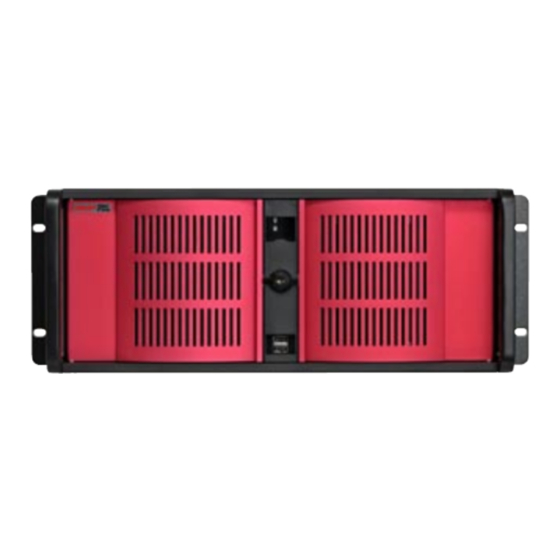
Unpacking the PRO 16/8 RAID DVR The PRO 16/8 RAID DVR comes securely packaged in a sturdy cardboard shipping carton. Upon receiving your DVR, open the carton and carefully remove the contents. If anything is missing or damaged, please contact your dealer immediately. - Page 17 Identifying External Components Please refer to the text and diagrams below to identify all external components and accessories of the PRO 16/8 RAID Digital Video Recorder. Front View Un-screw to open the door Un-screw to open the door Figure 1-1: Front View of the PRO 16/8 RAID DVR 1.
- Page 18 -Power LED: The Green LED light indicates that system power on -Fan and Thermal: The Green LED light indicates that the system fan and thermal are in normal status. The Red LED light indicates that the system fan and thermal are failed, Note ! When the Red LED is keeping blinking, please call help from your distributor...
- Page 19 Figure 1-3: Rear View of Digital Video Recorder 1. System Ventilation Fan This fan generates ventilation for the entire system 2. BNC Camera Input Use these four BNC camera inputs cards to connect 16 NTSC or PAL compatible cameras. 3. VGA Display Port This port is used to connect an external monitor (CRT) or TFT.
- Page 20 Preparing the Digital Video Recorder for Operation To prepare your Digital Video Recorder for operation, you should first connect all peripheral devices. Make sure the digital video recorder is turned off before you do this. Make sure the floppy drive does not contain a diskette; if it does, press the eject button to eject an inserted disk.
-
Page 21: Chapter 2
Chapter 2 ETTING TARTED This chapter explains what you need to do after turning on your Digital Video Recorder. Experienced Digital Video Recorder users may skip this chapter if necessary while using the rest of the manual merely as a reference. Powering Up the Digital Video Recorder for the First Time To connect the Digital Video Recorder to the Power outlet, please refer to Figure 2- 1 and the following instructions:... - Page 22 Once the boot process is complete, the Digital Video Recorder will display the cameras attached (See Figure 2-3). You will automatically be able to see all cameras connected. If a “ No Signal “ screen is displayed this means that the respective camera is not operating correctly, please check all connections, power supplies and the camera for the Video output fault.
- Page 23 The first viewable screen shows the cameras connected and also gives users’ a first glance at the GUI (Graphical User Interface). The viewable screen takes up 75% of the screen while the controls are to the right of the viewable cameras.
- Page 24 Understanding the PRO 16/8 RAID DVR Main Screen When starting the Digital Video Recorder for the first time, please ensure that you understand all of the DVR’s icons before moving on. Here is an explanation of all of the icons on the main screen. Right Hand Toolbar Day/Month/Year Time Indicator Settings Icon...
-
Page 25: Bottom Toolbar
Bottom Toolbar Figure 2-4: Bottom Toolbar Exit Icon Clicking this icon exits to the Main Screen (without camera view). Drawing Icon Clicking this icon will allow users to draw a specified motion detection frame in the viewing camera area. Erase Icon Clicking this icon will remove the specified motion detection frame. - Page 26 Logging on to and shutting down the PRO 16/8 RAID DVR When starting the Digital Video Recorder for the first time, the system will have “Admin” rights. Administration rights are available to the “Supervisor”. At this stage the “accounts” database is empty so users will have to enter the Logon using administrative rights.
- Page 27 Figure 2-7: The Main Settings and Programming screen Shutting down the system The PRO SERIES DVR is quite a versatile and easy to use Digital Recorder. It is easy to Logon, Logoff and Shutdown. In order to shutdown the DVR follow these few steps: Step 1:Click the Logon Icon.
-
Page 28: Chapter 3
Chapter 3 UICK UIDE TO CONS ON THE CREEN This chapter explains the quick access icons on the main screen. Some of these icon functions will be explained in depth later on in the manual. The Main Screen is the central hub of your PRO 16/8 RAID Digital Video Recorder. - Page 29 Figure 3-2: The Settings Main Screen “ example shown “ Clicking on separate “windows” will display different settings for the PRO 16/8 RAID DVR. The first window is the Camera screen (as shown above). See the chapter on “Configuring your ¹” much later in this manual. Playback Panel Step 1: Click the playback icon on the right-side toolbar………………….
- Page 30 Figure 3-3: The Playback Screen Clicking on separate “files” within the playback folder will display prerecorded data from its hard drive. The first window is the database log. See the chapter on “Viewing Playback images on your PRO 16/8 RAID DVR” much later in this manual.
- Page 31 Another way to view Single-mode Camera view is by clicking on a single camera within the Main Screen. Double-clicking that image several times will expand it to Single-mode camera view. Quad Camera View Screen Step 1: Click the quad view camera icon on the right-side toolbar… Step 2: The screen will display four cameras in one screen.
- Page 32 Depending how your system is configured, the DVR can be configured to display nine separate cameras at 6-second intervals. This can be configured in the main Settings Panel. This will be covered later in this manual. 16 – Camera View Screen (only for PRO 16/2 DVR + CD-RW(4U)) Step 1: Click the 16 - Camera view icon on the right-side toolbar…….
- Page 33 Full Screen Mode Step 1: Click the Full Screen view icon on the right-side toolbar…. Step 2: The screen will display all or the selected cameras connected to the DVR in Full Screen Mode. If the system has 16 cameras, sixteen cameras will occupy the entire screen.
-
Page 34: Chapter 4
Chapter 4 ONFIGURING THE AMERAS This chapter explains how to setup and configure the cameras connected to your PRO 16/8 RAID digital video recorder. Once you have connected all the cameras to your DVR, you need to enter “Setup” to configure each individual camera. Here users can set the camera information shown on-screen, set the background colours, adjust the lighting of each camera, set the image format and resolution, change the image quality, frame rate, and adjust the motion detection zones. - Page 35 Naming Cameras • Under “Cam Info” click into the camera-naming field, type in name. Tick Cam On/Off to display or disable the characters. (Max 8 characters) Figure 4-2: Camera Naming Field Setting Recording Mode • Under “REC Mode” select one of three options: i.
- Page 36 Figure 4-4: Camera Text & Background Colour Icons Adjusting Picture Quality • Under “Adjustment” users can use the slide bar to set various settings for “Hue” - Is the attribute of colours that permits them to be classed as red, yellow, green, blue.
- Page 37 Setting Recording Quality Under “Recording Quality”, there are four choices: Low, Medium, High and Best. Low produces highly compressed low image quality and Best offers high image quality. Here you can select the quality and frame rate of each camera. Figure 4-7: Recording Quality and Frame Rate (FPS) Frame Per Second.
-
Page 38: Setting Motion Detection
Setting Motion Detection • Under “Motion Detection” users can select: i. Sensitivity – To set the sensitivity relative to the motion detection zone (from 1 to 5). The higher the value, the more sensitive the detection will be. ii. Differentia - A Pulse Count factor that distinguishes differences among images within a given time. -
Page 39: Chapter 5
Chapter 5 CHEDULE ECORDING This chapter explains how to set schedule recording times for each camera connected to your PRO 16/8 RAID digital video recorder. Each camera can be configured to record at different times. There are four choices: Once, Daily, Weekly, and Monthly. Recording under different modes will affect the overall capacity of your Digital Video Recorder. - Page 40 Figure 5-2: Record Mode Selection Bar (Once) ii. Daily – Provides a recording option for Hours and Minutes. Figure 5-3: Record Mode Selection Bar (Daily) iii. Weekly – Provides a recording option set date (Sun. through Sat.) and time for recording every week.
- Page 41 Figure 5-4: Weekly Schedule Settings iv. Monthly – Provides a recording option that allows users to set date and time for recording every month Figure 5-5: Monthly Schedule Settings...
- Page 42 After you have selected the record mode and option, choose the camera to be assigned in any combination. Click on the “Add” button. The relative information will be shown in the schedule recording list If you wish to delete a particular entry. Select the entry and the Delete button. If you wish to modify a particular entry.
- Page 43 “Once” Only Scheduling Scheduling the Digital Video Recorder to record using the “Once” option gives users the choice to set the Day, Month, and Year, and then select a particular time for that date. The benefit is to create individual times for different cameras giving users the freedom to choose activate cameras at different times.
- Page 44 Daily Scheduling Choosing the “Daily” scheduling mode to set a particular period for recording each day. Select the “Daily” option The “Daily” option Select cameras Figure 5-8: Selecting Record Mode Select the camera you wish to configure. Select the recording duration Figure 5-9: Duration Selection Click “Add”...
- Page 45 Weekly Scheduling Choosing the “Weekly” scheduling mode, the user can set the desired day for recording every week, and then select a particular time for that date. Select the “Weekly” option The “Weekly” option Select cameras Figure 5-10: Selecting Record Mode Select the camera you wish to configure.
- Page 46 Monthly Scheduling Choosing the “Monthly” scheduling mode, the user can set the desired date for recording every month, and then select a particular time for that date. Select the “Monthly” option The “Monthly” option Select cameras Figure 5-12: Selecting Record Mode Select the camera you wish to configure.
- Page 47 Modifying Scheduled times To modify the schedule, you should click on the selected item from the Rec lists to change the record mode and record option, then click on the “Modify” button. Deleting Schedule Settings Deleting recorded data will permanently delete information from the hard disk drive thus to free-up disk space.
-
Page 48: Chapter 6
Chapter 6 CCOUNT ETTINGS The Account Settings area allows the administrator of the PRO 16/8 RAID DVR to add users to the system. There are two types of users, one with Supervisory (or Administrative) powers, and the other is Normal. A Normal user does not have supervisory powers and is limited to certain user ability of the PRO 16/8 RAID DVR system. - Page 49 Enter the name of the user followed by a specified password. Enter the password once again in the ”ReType” field to reconfirm. Enter the name of the user followed by a Specified password Click Figure 6-2: Name, Password & Confirmation Field Click the checkbox next to “...
- Page 50 Figure 6-3: Authority Selection Field The “Access Permissions” must be selected following the creation of each "Normal" user. Click the checkbox next to “Local” to give the user local access to the DVR host. (Local access means users are able to access the DVR directly.) Click the checkbox next to “Remote”...
- Page 51 Click “Modify” button Click “Apply” , then “OK” to confirm changes Figure 6-5: Modifying User Settings To Delete Users Select the user Click “delete” Click “Apply” , then “OK” to confirm the changes...
-
Page 52: Chapter 7
Chapter 7 YSTEM ETTINGS The System Settings Panel is for naming and setting basic configurations for the DVR. These very important settings will ensure that the DVR system may be correctly viewed both locally and remotely. Incorrect system configuration may result in abnormal operation and could make tech support more complex and time consuming. - Page 53 Type in a name for the DVR host (up to 32 letters) for the purpose of machine identification when sending an email alarm. Enter an IP address, Subnet Mask, and depress the LAN “diamond” to activate the “Default Router”. Type in the Default Router (Gateway) that your Administrator assigned you.
- Page 54 Modem Dialup DVR users can choose modem dial-up for connecting to a telephone line. Windows users can also dialup (using PPP) to DVR for remote monitoring. To set up modem dial-up: 1. Check the ”Dialup” in the Internet field and enter the ”TEL No.” (The phone no.
- Page 55 Printer Setup Please refer to Chapter 14 Backup Config. In this section: you are able to perform a back up copy of the system configuration files, this greatly aids in the reprogramming of the DVR in the event of failure occurring or if the system requires to be set back to Factory Default due to unknown Admin password entry.
- Page 56 then click “OK” ……. Setting the System Clock The System Clock is automatically adjusted according to the system BIOS. If the system crashes or becomes faulty then it would be necessary to change the system clock. After the changes are made click “Apply”, then “OK” Figure 7-5: System Clock Settings Other Settings Recycle Recording...
- Page 57 Select the user account you want to give “Auto Login” status to. Figure 7-7: Auto Login Field Click “Apply” , then “OK” Cam Auto Switch ___________________________________________________ The third option under “Others” makes it possible to view different cameras automatically. When the DVR is in Single View Mode, Quad View Mode, 9 Camera or 16 Camera Mode, it will automatically show different cameras at six- second intervals.
- Page 58 3. Click ”Apply”, then “OK” to activate the setting. Figure 7-9: Minimize Video Size Settings Number P Frames after I Frame The “Number P Frames after I Frame” setting refers to the manner in which MPEG-4 compression will be implemented by the DVR system. An “I” frame is the initial full frame of video information for any given scene, while a “P”...
- Page 59 When the P frame function is set to a value higher than the default setting, for every clip of video, less I Frames are sent, so the quality of the image will be normal, but transmission occurs more quickly and disk space is saved; on the contrary, when the P Frame function is set to a value lower than the default setting, more I frames are sent, and the quality of the image will be high, using more disk space and transmitting more slowly, so users should set this function...
- Page 60 New HD format Support file system for video recording onto a Hard Drive. The PRO 16/8 RAID DVR system provides selection of FAT or ext3 HD formatting. The default setting ext3 is highly efficient and more stable than FAT and not recommended to be changed and left as default ext3.
- Page 61 DNS Server 192.168.1.2 DVR Host Setting Mode (Virtual IP: 192.168.1.3): IP: 192.168.1.3 Netmask: 255.255.255 DNS Server: 192.168.1.2 Default Router: 192.168.1.1 Virtual Server IP: 211.23.141.2 With the above settings complete, connect through a browser to http://211.23.141.2/ , this will connect to the Host with the virtual IP address http://192.168.1.3/.
-
Page 62: Chapter 8
Chapter 8 LARM ETTINGS The Alarm Settings area allows the administrator of the PRO 16/8 RAID DVR to set alarms for a number of functions. The most important is setting alarms for motion detection on different cameras. This is a complex task so in order to understand this area please read over this part carefully. - Page 63 Figure 8-3: Trigger Period Field Then select one of the Triggering Devices from the “tab” windows below. Figure 8-5: Tab Window Selection Alarm Record Triggering...
- Page 64 Alarm Record Triggering provides event triggered video evidence and normally reacts with accelerated frame rate recording; therefore it is important the correct FPS is set to achieve the desired frame rate for capture. The following shows how to use Record Alarm: Click the Alarm Tab From “General”...
- Page 65 Alarm Sound triggering Alarms can be assigned to Sounds, follow the instructions below to set Alarm Sounds. Click the Alarm Tab first. Select the “Camera” Tick off the entire “Enable” field first, then select “ Enable” under “Trigger Period” Click the “Sound” Tab. Figure 8-8: Sound Tab Click on the “...
- Page 66 Choose a .wav file from the above window and click “OK” Select how many times you would like to repeat the alarm sound (up to 10 times) Figure 8-10: Select Repeated playback of sound Then click “Add” Click“Apply” , and “OK” Alarm Message triggering Alarm Pop –Up Screen Messages when enabled will show a message on GUI at the time of detecting alarm and details of the alarm.
- Page 67 Figure 8-11: Message Tab Then click “Add” , the window below will show “Message” Click “Apply” , and “OK” For example: once this function is enabled and Motion Detection is enabled on that particular camera, a pop-up screen will appear (as below) to warn users that the DVR has detected motion.
- Page 68 Alarm Email triggering Alarm Email triggering provides a text notice and video file by email at the time of detecting alarm. Follow the instructions below. Click the Alarm Tab Select the “ Camera” (see Figure 8-6) Select a “Trigger Period” (see Figure 8-7) Click the “Email”...
- Page 69 Alarm Voice Triggering Optional external 56K modem required COM Port 1 Alarm Voice provides a preprogrammed voice message upon alarm trigger to a mobile or landline phone through the modem connection. Follow the instructions below to set Alarm Voice. Click the Alarm Tab to select the “Camera” Select a “...
- Page 70 Figure 8-16: Fax Tab Type in the “Fax Number” Choose from the “Send” drop-down list how many pictures you would like to fax, 1 to 30 pictures may be chosen Then click “Add” , the window below will show “Fax” with the selections made.
- Page 71 Figure 8-17: Output Port Tab Select an Output Port; each output port number has a relative camera number. Tick off “ Enable/Disable” the icon with a tick is “ Enable” The Delay Trigger Tick off to The Active Duration “Enable/Disable” Figure 8-18: Output Port Field Select the “Delay Trigger”, with the unit of seconds, the delay time may be set from 0 to 999 seconds.
-
Page 72: Chapter 9
Chapter 9 & S LARM CREEN OTIFICATION When an alarm associated to a camera occurs, the surrounding border to the camera video display will flash Red on the Main GUI. The Alarm Log provides the administrator of the PRO 16/8 RAID DVR to monitor all alarms that were triggered. - Page 73 Click “Confirm” to continue or “Cancel” to restart Click “Apply” , then “OK” to complete the task Deleting all Logs Click the “Alarm Log” Tab Figure 9-4: Alarm Log Click “Del all” A confirmation pop-up screen will appear asking to reconfirm (see Figure 9-5 below) Figure 9-5: Confirmation Window Click “Confirm”...
-
Page 74: Chapter 10
Chapter 10 The User Log provides the administrator of the DVR to monitor all users that have accessed the DVR. This database tells the administrator who accesses the system, from where they accessed the system (local or remote), when they logged on, how long users were logged on, and (if the connection was remote) what was the IP address. - Page 75 Click the “User Log” Tab Figure 10-4: User Log Click “Del all” A confirmation pop-up screen will appear asking to reconfirm (see Figure 10-5 below) Figure 10-5: Confirmation Window Click “Confirm” to continue or “Cancel” to restart Click “Apply”, then “OK” to complete the task.
-
Page 76: Chapter 11
Chapter 11 ONFIGURING ENERAL URPOSE NPUTS UTPUTS The GPIO provides connections to multiple Alarm Inputs and Dry contact closure Outputs. (All models come standard fitted with a 4-in-out alarm I/O). Optional I/O ports can be added to max 16-in-out module making system integration easy and fuss free. - Page 77 Input Settings Every camera has a corresponding GPIO connection to an alarm input. Depending on their attributes, the inputs can be set to Normal Open (NO) or Normal Closed (NC) according to integration requirements. Individual delay timer periods can be set, so that the interval time of the DVR alarm inputs can be started when the sensors are triggered.
-
Page 78: Chapter 12
Chapter 12 Pan Tilt Zoom (PTZ) provides the administrator of the PRO 16/8 RAID DVR to configure and monitor all PTZ cameras that are connected to the DVR. The PRO 16/8 RAID DVR can be configured with many PTZ cameras. Currently, the system doesn’t have pre-configured PTZ camera support. - Page 79 Figure 12-2: Camera Selection Using the Dome controls to the bottom left of the “PTZ” window users can configure their PTZ cameras to move left , right , up , and down . This can be done using the control keys as illustrated below. Figure 12-3: Dome Settings &...
- Page 80 Iris When connecting a PTZ camera to your PRO 16/8 RAID digital video recorder you have the option to open the Iris and close the Iris on the camera. Use make the iris close, or use to make the iris open. Preset Setup The PRO 16/8 RAID digital video recorder gives you 128 preset functions.
- Page 81 Figure 12-7: Iris Controls 6. Click the “Speed” (range from 1 degree per second to 255 degrees per second) and “Time” (range from 0 to 255 seconds) from their respective drop-down lists to do adjustments, to preset speed and time for the PTZ camera at that preset point.. Present point Figure 12-8 Preset functions 7.
- Page 82 1. Create all the presets in the groups. 2. Choose the number of your desired group (Group 1, Group 2, Group 3 and Group 4) under the Pan Group. 3. Click “Set Group” button. 4. Click “ Auto Pan” then the PTZ cameras will begin to circumnavigate according to the presets in the group.
- Page 83 Note: Different Speed Dome models have different functionality; please refer to the user guide of the Speed Dome you wish to connect. Speed Dome type PRO 16/8 RAID DVR supports the below brand, please choose from the following icon: CD-55 (Min King) CD-55H (Min King) CD-56 (Min King) CD65 (Min King)
-
Page 84: Chapter 13
Chapter 13 LAYBACK Playback allows a user to view recorded history video data, as the system is recording, in live view mode and remotely. Other features within “Playback” are: Blur, Snapshot, Export, Tag, File, Alarm, Fast Forward, Slow Motion, Reverse Play &... - Page 85 Understanding the Recorded database The Pop-up database is the first start to viewing playback images. There are many aspects to the database. Lets take a closer look. Time search Figure 13-2: Pop-up Database Screen Calendar Search: Clicking the calendar button allows users to select the date by which they want to search.
- Page 86 Click this icon to exit playback. Click the directional icons to move the playback images up, down, left, or right. Click this icon to remove blur, sharpen or define the image. Click this icon to take a snapshot, save it or export a recorded image. Click this icon to save an image.
- Page 87 Viewing Playback by Camera To view a recorded file from a particular camera follow the next few steps To view Playback click the “playback” icon… Pop-up Database Bottom Toolbar Figure 13-4: Playback Screen Select a date and time from the calendar Figure 13-5: Calendar &...
- Page 88 Figure 13-6: Camera Database Choose the recorded clip to play Figure 13-7: Camera Selection Double-click the selection or click “ Open”. The selected file will appear in front of the Main Screen Figure 13-8 Recorded playback data...
- Page 89 Click “play” from the Bottom Toolbar Double-click the image to enlarge Figure 13-9: Enlarged Image Double-click the image again to enlarge Figure 13-10: Full-size Playback image To reduce the size or go back to the original size, just click the right mouse button.
- Page 90 Playback from the other devices To view the recorded data from other devices: Click the icon of “Other Path”, the “select record files” appears: Figure 13-10-1 Playback from other devices USB: Playback from a connected media device with saved data. USB HDD or USB handy drive, Memory Stick (Please note that the USB device should be connected to DVR before powering on) Neighbor: Playback recorded data stored on a server hard drive through a...
- Page 91 Alarm Recorded Playback To view alarm triggered playback images • Click the alarm icon • A database of alarm triggered playback files will appear (Alarm Log) Figure 13-11: Alarm Log • Please select the file you want from the alarm video log. Double-click it. Or click “Open”.
- Page 92 Tagging recorded data After opening a file, an important section of the video can be tagged for later reference and archiving. While watching the video frames, the tagged section can be operated like this. Click the “Tag” . Button to enter the window Figure 13-13: Tag field Type in the Tag name first.
- Page 93 Figure 13-15: Tagged Clip Exporting a Clip While viewing playback data, if you wish to export a section of one clip to save in addition, do as follows: Click on this icon . The following image will appear: Figure 13-16: Export image The image highlights the hours, minutes, and seconds.
- Page 94 Figure 13-17: Export Clip Smoothing an Image The smoothness and sharpness of an image can be adjusted in the DVR. When an image is unclear it is important to clarify the image more clearly. Figure 13-18: Sharpen Image • Open the recorded image •...
- Page 95 Figure 13-19: Blur Image Moving playback frames While viewing several playback screens, the entire screen or background screen may be unclear. The directional icons can be used to move each playback video to different parts of the screen. Click on the separate directions to position your video in the right place.
- Page 96 Figure 13-21: More than one playback image...
-
Page 97: Chapter 14
Chapter 14 RINTING One of the unique features of the PRO 16/8 RAID is its ability to print still images. Printing images from your digital video recorder can clarify certain factors you cannot see from an image on your monitor. The PRO 16/8 RAID DVR accepts many forms of printers. - Page 98 Figure 14-2: Printer Configuration Select your Printer Type, choose the Paper Size, to set the size of paper, and “ Resolution “ to set the resolution, and then “ Colour depth/Unprint Mode” to set the colours (for colour printers). Click OK A pop-up screen will appear prompting you to print a test page Figure 14-3: Printer Test Page Click Confirm to continue.
- Page 99 Printing an image Click the Playback” icon……………………………… A pop-up database will appear giving you the choice of selecting a file, selecting the date, searching, or by checking the list. At the bottom of the screen you will notice a set of icons. These icons will help later when using the playback image. Pop-up Database Bottom Toolbar Figure 14-4: The Playback Screen...
- Page 100 The database for that camera will open Figure 14-6: Camera Database Select the date and time to view the clip. Figure 14-7: Camera Selection Double-click the selection or click “ Open” The selected clip will appear in front of the Main Screen...
- Page 101 Figure 14-8: Recorded playback data Click “play” from the Bottom Toolbar Click the “Snapshot” icon, and a new window will appear to show the image that has been taken. (Before taking a snapshot, press the “ pause “ button to freeze the picture) Click the “Export”...
-
Page 102: Chapter 15
URVEILLANCE The PRO SERIES DVR offers up-to-date IT technology standards and places itself in a unique bracket of excellence. The PRO SERIES DVR provides users with the capability to view live, and recorded data remotely. Currently many systems can support network capability but not many can support the same functions like the PRO SERIES DVR. - Page 103 Figure 15-2: Browser IE. In the address field enter the IP address Hit Enter. The remote window will appear. Figure 15-3: Browser Window Under Name enter admin Under Password enter admin (The default password) Click Login...
- Page 104 The next screen is the main Remote Browser Screen Figure 15-4: The Main Remote Surveillance Screen The Main Remote Surveillance Screen has four parts to it. They are Monitor, Playback, Setup, and Logout. • Monitor – Click this area to preview still images and monitoring live images and video.
- Page 105 1. Click Monitor Once you have clicked on Monitor a new screen will appear previewing all cameras connected to your PRO SERIES digital video recorder. These are static images taken from each camera. Figure 15-5: Remote Monitor Screen- Remote Monitoring...
- Page 106 Single Remote View Figure 15-6: Single Remote View Quad Remote View Figure 15-7: Quad Remote View...
- Page 107 6-Camera Remote View Figure 15-8: 6-Camera Remote View 12-Camera Remote View Figure 15-9: 12-Camera Remote View Depending on the speed of your LAN or Internet connection, the viewing quality will change. Faster connections means better viewing capability. Configuring Setup Remotely The functions for setup remotely are exactly the same as they are locally.
- Page 108 1. On the Main Remote Screen click Setup Setup Link Figure 15-10: Main Remote Screen for Setup 2. The first screen is the Camera setup browser window Figure 15-11: The Remote Camera Configuration Screen All remote functionality is similarly setup as the local machine. The only difference is the way the interface looks.
- Page 109 3. Click the Schedule link to view the Remote Schedule Settings Figure 15-12: Remote Schedule Screen The remote schedule screen is divided into various parts for easy configuration. Select the recording mode, and cameras to start the configuration. Figure 15-13: Remote Scheduling 4.
- Page 110 Figure 15-14: Remote Calendar scheduling 5. Click “Add” to activate the settings. Once you have completed all schedule settings you can view a log of all changes. Figure 15-15: Remote Schedule Log...
- Page 111 Modifying Scheduled Settings 1. Click the data you wish to modify Click on the data intended to modify Figure 15-16: Remote Modify Window 2. Click the Modify icon Figure 15-17: Remote Modify Parameters 3. View the modifications Figure 15-18: Modifying a Schedule remotely...
- Page 112 Configuring remote account settings provide administrators the chance to configure user settings from a remote site. This enables the administrator to make changes to the PRO SERIES DVR without the need to visit the DVR. 1. Click the Account Settings link on the browser. The administrator will see...
- Page 113 Figure 15-20: Adding users remotely The same ease-of-use can be done with other functions.
- Page 114 Remote System Setup 1. Click on the System Settings link in the browser window Figure 15-21: Remote System Settings Here some of the functions are different from the main screen. As administrator you do not have to change the IP address functions on this screen. If these changes are made you will lose the connection.
- Page 115 Remote Alarm Setup Remote alarm functions give users the opportunity to change alarm functions from a remote site. Figure 15-22: Remote Alarm Settings Once you have made the selective choices available under Remote Alarm settings, click OK to make the changes effective Figure 15-23: Remote Alarm verification...
- Page 116 Remote Alarm Log Viewing The current settings provide the administrator to view and delete all alarm logs. Click on the Alarm Log link. You will see the screen below. Figure 15-24: Remote Alarm Log If you would like to delete all logs, click in the checkbox next to “Select All”. To delete individual logs click next to the checkbox of the file you want to delete and click the Delete icon.
- Page 117 Remote User Log The administrator can view all users that have logged onto the system. This means the administrator can have real-time evaluation of users accessing the machine. Click the Login Log link to view the user log remotely Figure 15-25: Remote User Log If you would like to delete all logs, click in the checkbox next to “Select All”.
- Page 118 Remote Playback Go back to the Main Screen Figure 15-26: The Remote Playback Link Understanding the Playback Side Toolbar The playback sidebar gives users many choices. These choices give users the freedom to manipulate the image to their benefit. Lets take a closer look.
- Page 119 (4) Playback (5) Reverse Button (6) Pause Button (7) Previous Button (8) Next File Button (1) File button (2) Alarm File button (3) Tag File button (9) Snapshot Button (10) Export file (11) Tag Add Button (12) Playback Speed (13) Zoom button Figure 15-27: Playback Side Toolbar 1.
- Page 120 Figure 15-27: The Remote Playback screen In this remote playback-viewing window, there are three choices to access the playback files. The choices are File (from a particular file), Alarm File, and Tag File. The figure below shows the operation function keys of each video screen. You may fast-forward at 2,4,6,8 or 10 times speed.
- Page 121 Playback by File In order to view files or playback recorded data from the PRO SERIES DVR remotely. Once you have clicked the File icon, a new pop-up window will appear. 1. Select the camera, and the time you wish to preview.
- Page 122 Figure 15-31: Remote Playback image When you want to see the image enlarged, just click the “Zoom In” button and then the image will be enlarged. See image below. Figure 15-32: Remote Playback Enlarged Image...
- Page 123 Taking a Snapshot The PRO SERIES DVR gives users the opportunity to take pictures of recorded data. While viewing the playback image, there might be a time when you would like to take snapshots of video and print it out. In order to do this: Click the Snapshot button From the pop-up window, select the resolution size of your print.
- Page 124 Figure 15-34: Printer Selection Select your printer and click OK Exporting an Image Exporting an image allows users to access images from the hard disk and save it onto your local hard drive. 1. Click the Export button 2. Select an exporting duration Figure 15-35: Export Duration 3.
- Page 125 Figure 15-37: Saving to Location Inserting a Tag Inserting a tag allows users the choice to watermark an image or recorded video so that they can reference it in the future. To create a tag: 1. Click the Tag button on the playback side toolbar 2.
- Page 126 Figure 15-40: The Tagged playback file Remote GPIO Settings The operation on remote GPIO is the same with local settings on DVR host. Once you have added all the GPIO modes, click “ OK” in the right corner to save the changes to the DVR Host and make them effective.
-
Page 127: Pro 16/8 Raid Software Probe Function
Appendix A PRO 16/8 RAID SOFTWARE PROBE FUNCTION In order to use “Backup to NAS”, “NTP”, and “Multi-Playback” functions of your DVR, you must purchase and install one KEYPROBE from your vendor this is optional. Connect the optional KEYPROBE with the print port. (The printer port remains operational and can be connected to a printer) - Page 128 Backup to NAS (Network Attached System) Because the image data of the DVR are larger than common file data, the demand on storage space will be higher. NAS can support IP network protocols; therefore users can backup their DVR data to NAS through Internet/LAN at anytime. Steps: 1.
- Page 129 4. Enable: Click the ‘‘enable’’ checkbox to enable the NAS feature. 5. Path: Fill in the backup pathname including the IP/Host name of NAS and the DVR backup folder name on NAS (example: in the above picture, Backup stands for the host name of NAS and nas1 is the name of DVR backup folder.) Note: One NAS can connect multiple DVR hosts, in order not to conflict the back-up data;...
- Page 130 NTP (Network Time Protocol) The Network Time Protocol (NTP) is used to synchronize the clock of a DVR to another reference time source. Steps: 1. Click the ‘’Setup’’ icon on the main screen. 2. Click the ‘’System’’ tab. 3. Click the ‘’NTP’’ button to popup the NTP setup windows.
- Page 131 4. NTP Server: Fill in the ‘’NTP Server’’ and click the ‘’Add’’ button to put the NTP server into the list. DVR can have their own time server added for keeping a DVR synchronized. (Several NTP servers have been added by default) 5.
- Page 132 Multi-Playback Let’s take a look at how we can use the multi-playback function. 1.Click the ‘’playback button on the main screen, and then click (multi- playback), you’ll see the Multi-Playback windows as below. 2. Click to select the playback clips according to cameras and date/time. 3.
- Page 133 5. You can use “Hour ” and “Minute ” to change the start playback time. (Example: Click the hour , the playback time will be changed from 14:00 to 15:00.) 6. You can click any camera view to zoom the image.
-
Page 134: Troubleshooting
Appendix B ROUBLESHOOTING Your Digital Video Recorder has passed through a series of rigorous quality assurance tests to guarantee reliable performance. However, your new Digital Video Recorder is a sophisticated piece of equipment and as such may malfunction if used incorrectly or if one of its components fails. - Page 135 To check the power cables, and connections: • Check the power outlet or power strip with an item that you know is functioning properly. A lamp or radio is a convenient item for checking the power. You may also need to check the fuses and breakers in your electric box. •...
- Page 136 In general, if the POS detects a system board failure (a critical error), the Digital Video Recorder halts and sends out a series of beeps. If failure is detected in an area other than the system board (such as the display, keyboard or mouse) an error message is displayed on the screen and testing is stopped.
- Page 137 General Hardware Problem A few common hardware problem and suggested solutions are presented in the table below: Problem Solution You turn on the Check the power LED indicator. If it is on (GREEN) then power is being supplied to the Digital Video Recorder. If Digital Video the LED is not on, make sure that the power cord is Recorder...
- Page 138 The diskette is full. Try using another diskette or free up some space on the diskette. The floppy disk drive is not operating. Contact your dealer for support. Contacting Your Dealer If you still have a problem after reading the preceding sections, the next step is to contact your dealer.
- Page 139 Appendix C ONFIGURING CTIVE ActiveX is a type of Vscript. Basing on the communication between ActiveX and The main application, the naming space provided for the programmer can be managed successfully. ActiveX Settings The relative settings about the security of ActiveX can be configured in the way below: •...
- Page 140 (1). Click to choose the” Trusted Sites” Figure b-2: Creditable Website Tab (2). Click “ Sites” Icon. Figure b-2: Creditable Website Tab (3). Add this website to this field. (4). Cancel the selection of “Require server verification (https) for all sites in this zone “...
- Page 141 Appendix D Warranty One year warranty from the date of purchase against defects in materials or workmanship, when the PRO 16/8 RAID DVR is installed and, operated in accordance with the instructions provided in this user’s manual and is in normal use.
- Page 142 Head Office: Ness Security Products Pty Ltd ABN 28 069 984 372 4 / 167 Prospect Hwy Seven Hills NSW 2147 Australia Ph +61 2 8825 9222 Fax +61 2 9674 2520 ness@ness.com.au NSW: 4 / 167 Prospect Highway...
Need help?
Do you have a question about the Pro series and is the answer not in the manual?
Questions and answers