
Related Manuals for Kramer VP-553


Summary of Contents for Kramer VP-553
- Page 1 K R A ME R E LE CT R O N IC S L TD . USER MANUAL MODEL: VP-553 Presentation Switcher/Scaler P/N: 2900-300326 Rev 2...
-
Page 4: Table Of Contents
Figures Figure 1: VP-553 Presentation Switcher/Scaler Front Panel Figure 2: VP-553 Presentation Switcher/Scaler Rear Panel Figure 3: Connecting the VP-553 Presentation Switcher / Scaler Figure 4: Balanced Stereo Audio Connection Figure 5: Unbalanced Stereo Audio Output Connection Figure 6: balanced Stereo Audio Input Connection Figure 7: Unbalanced Stereo Audio Input Connection VP-553 –... - Page 5 Figure 41: The EDID Page – Copying the Native Timing Figure 42: The EDID Page – Copying the Default Figure 43: The EDID Page –The Copy EDID Results Figure 44: The Data Routing Page Figure 45: The Authentication Page Figure 46: The About Page VP-553 - Contents...
-
Page 6: Introduction
Introduction Welcome to Kramer Electronics! Since 1981, Kramer Electronics has been providing a world of unique, creative, and affordable solutions to the vast range of problems that confront video, audio, presentation, and broadcasting professionals on a daily basis. In recent years, we have redesigned and upgraded most of our... -
Page 7: Getting Started
Avoid interference from neighboring electrical appliances that may adversely influence signal quality Position your Kramer VP-553 away from moisture, excessive sunlight and dust This equipment is to be used only inside a building. It may only be connected to other equipment that is installed inside a building. -
Page 8: Safety Instructions
Kramer Electronics has made arrangements with the European Advanced Recycling Network (EARN) and will cover any costs of treatment, recycling and recovery of waste Kramer Electronics branded equipment on arrival at the EARN facility. For details of Kramer’s recycling arrangements in your particular country go to our recycling pages at http://www.kramerelectronics.com/support/recycling/. -
Page 9: Overview
System Range for the TP inputs and outputs - over 250m (more than 820ft) For optimum range and performance using TP, use Kramer's BC-STP cable where skewing is not an issue or the Kramer BC-XTP Unshielded Twisted Pair (UTP) skew-free cable. Note that the transmission range depends on the signal resolution, source and display used. - Page 10 Built-in ProcAmp - color, hue, sharpness, noise, contrast and brightness Front panel control - audio mute, video blanking and freeze frame Built-in Web pages for easy setup and remote control Firmware upgrade via the Ethernet Non-Volatile memory that saves the final settings VP-553 – Overview...
-
Page 11: Using The Usb Switcher
Via the Ethernet with built-in Web pages The VP-553 is housed in a 19” 2U rack mountable enclosure, with rack “ears” included, and is fed from a 100-240 VAC universal switching power supply. Using the USB Switcher The VP-553 incorporates a simple, yet effective, 4:1 USB 1.1 switcher. The switcher can be used, for example, to connect one out of several PCs to a smart board or other USB client. -
Page 12: Shielded Twisted Pair (Stp) / Unshielded Twisted Pair (Utp)
STP cable. There are different levels of STP cable available, and we advise you to use the best quality STP cable that you can afford. Our non-skew-free cable, Kramer BC-STP is intended for analog signals where skewing is not an issue. -
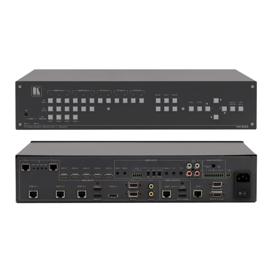
Page 13: Figure 1: Vp-553 Presentation Switcher/Scaler Front Panel
Figure 1: VP-553 Presentation Switcher/Scaler Front Panel Feature Function IR Receiver Receives signals from the remote control transmitter OSD OUT LEDs Red LEDS indicate whether the OSD is displayed on OUT 1 and/or OUT 2 TO USB OUT Press a button to switch a USB input to the output (from USB 1 to USB 4) -
Page 14: Figure 2: Vp-553 Presentation Switcher/Scaler Rear Panel
EQ. Trimmer Use to adjust the cable compensation equalization level HDBT IN Connect to an HDBT Transmitter (for example, the Kramer TP-580Txr) to pass audio and video signals as well as serial commands (from 1 to 3) HDMI IN Connect to the HDMI source (from 1 to 3) - Page 15 OUT 1 HDMI Connect to an HDMI acceptor OUTPUT HDBT RJ-45 Connect to an HDBT Receiver (for example, the Kramer TP-580Rxr) Connectors OUT 2 Connect to an HDMI acceptor ETHERNET Connector Connects to the PC or other Serial Controller through computer networking...
-
Page 16: Installing In A Rack
Installing in a Rack This section provides instructions for rack mounting the unit. VP-553 - Installing in a Rack... -
Page 17: Connecting The Vp-553
INPUT connector (from 1 to 3). Alternatively, you can connect the DVI connector on the DVD player to the HDMI connector on the VP-553 via a DVI-HDMI adapter. When using this adapter, you can connect the audio signal via the terminal block connector 2. - Page 18 RS-232 CONTROL 9-pin D-sub Port to a PC to control the unit 12. Connect the REM 2-pin terminal block contact-closure remote-control pins to a switch to mute/unmute the audio output by momentarily pressing the switch. 13. Connect the ETHERNET port, see Section 6.4 VP-553 - Connecting the VP-553...
-
Page 19: Figure 3: Connecting The Vp-553 Presentation Switcher / Scaler
Figure 3: Connecting the VP-553 Presentation Switcher / Scaler VP-553 - Connecting the VP-553... -
Page 20: Connecting The Balanced Stereo Audio Input And Outputs
Connecting the Balanced Stereo Audio Input and Outputs Figure 4: Balanced Stereo Audio Figure 5: Unbalanced Stereo Audio Output Connection Connection Figure 7: Unbalanced Stereo Audio Input Figure 6: balanced Stereo Audio Input Connection Connection VP-553 - Connecting the VP-553... -
Page 21: Controlling The Vp-553
Section 6.5) Controlling via the Front Panel Buttons The VP-553 includes the following front panel buttons: Input selector buttons for selecting the required input: CV (1 and 2), TP (1 and 2), PC (1 and 2), HDBT (1 to 3), or HDMI (1 to 3) to OUT 1 ... -
Page 22: Using The Osd Menu
Using the OSD Menu The control buttons let you control the VP-553 via the OSD menu. Press the: MENU button to enter the menu The default timeout is set to 10 seconds ENTER button to accept changes and to change the menu settings ... - Page 23 1280x720P 50 1440x900 1440x900 60 1080i @50Hz 1920x1080I 50 1400x1050 1400x1050 60 1080p @50Hz 1920x1080P 50 1680x1050 1680x1050 60 Native - Select Native to select the output resolution from the EDID of the connected HDMI monitor VP-553 - Controlling the VP-553...
- Page 24 Select the audio delay time: OFF, 10ms to 80ms in 10ms steps or DYNAMIC MICROPHONE MIX Set mix ON to mix the microphone input with the selected audio input or set to OFF MIX LEVEL Adjust the mix level (enabled when MICROPHONE MIX is set to ON) VP-553 - Controlling the VP-553...
- Page 25 Set the audio EQ values in 0.5dB steps for: BELOW 120Hz, CENTER 200Hz, CENTER 500Hz, CENTER 1200Hz, CENTER 3000Hz, CENTER 7500Hz and ABOVE 12000Hz NO SIGNAL window if no signal is detected Select a BLUE or BLACK color COLOR VP-553 - Controlling the VP-553...
- Page 26 EQ SAME AS Set to NONE, OUTPUT 1 or OUTPUT 2 AUDIO EQ Set the audio EQ values in 0.5dB steps for: BELOW 120Hz, CENTER 200Hz, CENTER 500Hz, CENTER 1200Hz, CENTER 3000Hz, CENTER 7500Hz and ABOVE 12000Hz VP-553 - Controlling the VP-553...
-
Page 27: Connecting To The Vp-553 Via Rs-232
OFF: the information is not shown ON: the information is shown permanently INFO: the information is shown for a few seconds Connecting to the VP-553 via RS-232 The VP-553 features two RS-232 ports: RS-232 DATA to pass data to and from the machines that are connected to the HDBT connectors ... -
Page 28: Operating Via Ethernet
You can connect to the VP-553 via an RS-232 connection using, for example, a PC. Note that a null-modem adapter/connection is not required. To connect to the VP-553 via RS-232 Connect the RS-232 9-pin D-sub rear panel port on the product unit via a 9-wire straight cable (only pin 2 to pin 2, pin 3 to pin 3, and pin 5 to pin 5 need to be connected) to the RS-232 9-pin D-sub port on your PC. -
Page 29: Figure 8: Local Area Connection Properties Window
4. Highlight either Internet Protocol Version 6 (TCP/IPv6) or Internet Protocol Version 4 (TCP/IPv4) depending on the requirements of your IT system. 5. Click Properties. The Internet Protocol Properties window relevant to your IT system appears as shown in Figure 9 Figure VP-553 - Controlling the VP-553... -
Page 30: Figure 9: Internet Protocol Version 4 Properties Window
Figure 9: Internet Protocol Version 4 Properties Window Figure 10: Internet Protocol Version 6 Properties Window VP-553 - Controlling the VP-553... -
Page 31: Figure 11: Internet Protocol Properties Window
8. Click Close. 6.4.2 Connecting the Ethernet Port via a Network Hub or Switch You can connect the Ethernet port of the VP-553 to the Ethernet port on a network hub or using a straight-through cable with RJ-45 connectors. 6.4.3... -
Page 32: Controlling Via The Infrared Remote Control Transmitter
Controlling via the Infrared Remote Control Transmitter You can control the VP-553 from the infrared remote control transmitter: Keys Function POWER Toggle the power save mode ON or BLANK Toggle between a blank screen black screen and the display (for... -
Page 33: Using The Embedded Web Pages
Using the Embedded Web Pages The VP-553 can be operated remotely using the embedded Web pages. The Web pages are accessed using a Web browser and an Ethernet connection. Before attempting to connect: Perform the procedures in Section 6.4. -
Page 34: The Switching Page
(audio, video or audio-follow-video) the Audio out (below Output) shows the audio input that is routed to the line and monitor outputs. The volume area lets you control the Line and Monitor output audio level. VP-553 - Using the Embedded Web Pages... -
Page 35: Figure 15: The Switching Page
Figure 16 explains the icons used to switch inputs and outputs. Figure 16: Switching Page – Input and Output Icons You can also edit the input and output button by clicking the edit icon. VP-553 - Using the Embedded Web Pages... -
Page 36: Figure 17: Edit Output Buttons
ON or OFF and set the Auxiliary level as well as the output volume and the IR transmission route to the HDBT output (see Section 7.2.1). OUT 2 does not include the IR routing selection line: Figure 18: Edit Output Buttons VP-553 - Using the Embedded Web Pages... -
Page 37: Figure 19: Edit Input Buttons
Figure 16) is slightly different for each input type. When selecting an HDMI input you can rename the input, set the embedded and analog audio volume and set HDCP to ON or OFF: VP-553 - Using the Embedded Web Pages... -
Page 38: Figure 20: Switching Page - Hdmi Input Window
(see Section 7.2.1): Figure 21: Switching Page – HDBT input Window For HDBT inputs, when a Kramer SID-X2N unit is connected to the HDBT input, click the SID-X2N icon (see Figure 22) to open the SID-X2N setup window (see Figure 23). -
Page 39: Figure 22: Switching Page - Sid-X2N Setup Icon
When connecting a PC or TP or CV input, you can rename the input and set the analog audio: Figure 24: Switching Page – PC, TP or CV input Window VP-553 - Using the Embedded Web Pages... -
Page 40: Figure 25: Hdbt Ir Transmission Example
External IR Sensor. The IR signal passes through the TP cables, the VP-553 and the IR Emitter to the DVD player, which responds to the command sent. At the same time you can also set HDBT 3 to... -
Page 41: The Scaler Page
Scaler page for output 1 which includes the picture setup and the PC mode setup. Note that when the PC inputs are connected all the settings are available. If TP is selected, only the WXGA/XGA is enabled otherwise, PC mode is disabled. VP-553 - Using the Embedded Web Pages... -
Page 42: Figure 26: The Scaler Page - Output 1
Figure 26: The Scaler Page – Output 1 When an analog input is connected, the PC mode is enabled: Figure 27: The Scaler Page – Output 1 for an Analog Input Figure 28 shows the setup for output 2: VP-553 - Using the Embedded Web Pages... -
Page 43: Figure 28: The Scaler Page - Output 2
Figure 28: The Scaler Page – Output 2 VP-553 - Using the Embedded Web Pages... -
Page 44: The Device Settings Page
Ethernet parameters. Figure 29: The Device Settings Page Any change in the device settings requires confirmation, as illustrated in the example in Figure Figure 30: The Device Settings Page – Static IP Confirmation VP-553 - Using the Embedded Web Pages... -
Page 45: Figure 31: The Device Settings Page - Uploading The New Firmware File
Figure 32: The Device Settings Page – New Firmware Updated 7.4.2 Soft Factory Reset Click the Soft Factory Reset button to reset all the device parameters except for the IP Address. The following message appears: VP-553 - Using the Embedded Web Pages... -
Page 46: The Usb Routing Page
The USB page lets you select one of the USB hosts (buttons USB 1, USB 2, USB 3 or USB 4 – in the example in Figure 34, USB 1 is selected). The selected button is routed to the USB client. VP-553 - Using the Embedded Web Pages... -
Page 47: The Audio Settings Page
Note that the DIP-switch settings cannot be changed via the Web pages only physically on the rear panel. The Input tab (see Figure 36) lets you set the volume individually for each input, including the analog and embedded audio HDMI signals. VP-553 - Using the Embedded Web Pages... -
Page 48: Figure 36: The Audio Settings Page - Inputs
Figure 36: The Audio Settings Page – Inputs Figure 37 shows the output 1 equalizer settings: Figure 37: The Audio Settings Page – Output 1 VP-553 - Using the Embedded Web Pages... -
Page 49: Figure 38: The Audio Settings Page - Output 2
Figure 38: The Audio Settings Page – Output 2 Figure 37 shows the Monitor equalizer settings as well as the volume of the Aux, Line and Monitor volume levels: Figure 39: The Audio Settings Page – Monitor VP-553 - Using the Embedded Web Pages... -
Page 50: The Edid Page
(HDMI/HDBT or VGA) to one or more selected inputs. Figure 40: The EDID Page Figure 41 shows how to select a resolution from the list and select one or more inputs. To copy, click the Copy button: VP-553 - Using the Embedded Web Pages... -
Page 51: Figure 41: The Edid Page - Copying The Native Timing
To copy, click the Copy button: Figure 42: The EDID Page – Copying the Default VP-553 - Using the Embedded Web Pages... -
Page 52: The Data Routing Page
Ethernet port to one of the HDBaseT inputs or the HDBaseT output Ethernet-General, you can transmit data from a controller connected via the connected SID-X2 to the HDBaseT input to which it is connected VP-553 - Using the Embedded Web Pages... -
Page 53: The Authentication Page
Flow Control: OFF or ON This way you can set the serial data in line with the serial data passed through. SID-X2N Data transfer: if the Kramer SID-X2N is connected to an HDBT port The Authentication Page The Authentication page lets you set the user name and password as well as setting the inactivity logout. -
Page 54: The About Page
Figure 45: The Authentication Page 7.10 The About Page The VP-553 About page lets you view the Web page version and Kramer Electronics Ltd details. Figure 46: The About Page VP-553 - Using the Embedded Web Pages... -
Page 55: Technical Specifications
19" x 7" x 2U (W, D, H) rack mountable WEIGHT: 2.7kg (6lbs) approx. INCLUDED ACCESSORIES: Power cord, rack ears, IR remote control Kramer BC−HDKat6a cable OPTIONS: Specifications are subject to change without notice at http://www.kramerelectronics.com VP-553 - Technical Specifications... -
Page 56: Default Communication Parameters
192.168.1.39 Subnet mask: 255.255.255.0 Default gateway: 192.168.1.254 TCP Port #: Not supported Default UDP Port #: 50000 Maximum UDP Ports: Full Factory Reset Go to : Menu-> Factory-> RESET->Change the option to YES and press Enter VP-553 - Technical Specifications... -
Page 57: Input Resolutions
1152x864 @75Hz 1280x720 @60Hz 1280x768 @60Hz 1280x800 @60Hz 1280x960 @60Hz 1280x1024 (@60/75Hz) 1360x768 @60Hz 1400x1050 @60Hz 1440x900 @60Hz 1600x900 RB @60Hz 1600x1200 @60Hz 1680x1050 RB @60Hz 1920x1080 @60Hz 1920x1200 RB @60Hz 480I/576I 480P/576P 720P(@50/60Hz) 1080I(@50/60Hz) 1080P(@24/30Hz) 1080P(@50/60Hz) VP-553 - Technical Specifications... -
Page 58: The Vp-553 Rs-232 Communication Protocol
The VP-553 RS-232 Communication Protocol The VP-553 can be operated using serial commands from a PC, remote controller, or touch screen. The unit communicates using the default Kramer Protocol 3000. Kramer Protocol 3000 syntax (see Section 9.1) Kramer Protocol 3000 command list (see Section 9.2) - Page 59 CRLF – For machine messages; carriage return (ASCII 13) + line-feed (ASCII 10) Command chain separator character When a message string contains more than one command, a pipe ( '|' ) character separates each command. Spaces between parameters or command terms are ignored. VP-553 - The VP-553 RS-232 Communication Protocol...
- Page 60 You can directly enter all commands using a terminal with ASCII communications software, such as HyperTerminal, Hercules, etc. Connect the terminal to the serial or Ethernet port on the Kramer device. To enter CR press the Enter key. ( LF is also sent but is ignored by command parser).
-
Page 61: Kramer Protocol 3000 - Command List
Lock front panel #LOCK-FP? LCK? GET Lock front panel #HDCP-MOD #HDCP-MOD? #VID-RES Set input/output resolution #VID-RES? Get input/output resolution #VMUTE #VMUTE? #VFRZ #VFRZ? #AUD-LVL Set audio level #AUD-LVL? Get audio level #MIX #MIX? #MIX-LVL #MIX-LVL? VP-553 - The VP-553 RS-232 Communication Protocol... - Page 62 Command Short Form Description #MUTE #MUTE? #SCLR-AS #SCLR-AS? #IMAGE-PROP #IMAGE-PROP? #SCLR-PCAUTO #SCLR-AUDIO-DELAY #SCLR-AUDIO-DELAY? #EQ-LVL #EQ-LVL? #SHOW-OSD #SHOW-OSD? #MIC-GAIN #MIC-GAIN? #DPSW-STATUS? VP-553 - The VP-553 RS-232 Communication Protocol...
-
Page 63: Kramer Protocol 3000 - Detailed Commands
Monitor OUT Aux IN 9.3.2 The Resolutions key Resolution Resolution Native 640x480 800x600 1920x1200 1024x768 480P60 1280x768 720P60 1360x768 1080P60 1280x720 1080I60 1280x800 1280x1024 576P50 1440x900 720P50 1400x1050 1080P50 1680x1050 1080I50 1600x1200 1920x1080 VP-553 - The VP-553 RS-232 Communication Protocol... - Page 64 Get : Response ~nn@BUILD-DATE␠date␠time␍␊ Parameters date – Format: YYYY/MM/DD where YYYY = Year, MM = Month, DD = Day time – Format: hh:mm:ss where hh = hours, mm = minutes, ss = seconds VP-553 - The VP-553 RS-232 Communication Protocol...
- Page 65 Command Type – System-mandatory PROT-VER? Command Name Permission Transparency Set: PROT-VER? Get: End User Description Syntax Set: Get : Get protocol version #PROT-VER?␍ Response ~nn@PROT-VER␠3000:version␍␊ Parameters Version – Format: XX.XX where X is a decimal digit VP-553 - The VP-553 RS-232 Communication Protocol...
- Page 66 Command Name Permission Transparency Set: Get: NET-MAC? End User Description Syntax Set: Get : Get MAC address #NET-MAC?␍ Response ~nn@NET-MAC␠mac_address␍␊ Parameters mac_address – Unique MAC address. Format: XX-XX-XX-XX-XX-XX where X is hex digit. VP-553 - The VP-553 RS-232 Communication Protocol...
- Page 67 Get: ~nn@ NET-GATE ␠ ip_address ␍␊ Parameters P1 (valid IP address)=xxx.xxx.xxx.xxx Notes A network gateway connects the device via another network and maybe over the Internet. Be careful of security problems. For proper settings consult your network administrator VP-553 - The VP-553 RS-232 Communication Protocol...
- Page 68 To connect with a randomly assigned IP by DHCP, specify the device DNS name (if available) using the command “NAME”. You can also get an assigned IP by direct connection to USB or RS-232 protocol port if available. For proper settings consult your network administrator. VP-553 - The VP-553 RS-232 Communication Protocol...
- Page 69 Response is sent to the com port from which the Set was received (before execution) Notes Destination bitmap size depends on device properties (for 64 inputs it is a 64-bit word) Example: bitmap 0x0013 means inputs 1,2 and 5 are loaded with the new EDID VP-553 - The VP-553 RS-232 Communication Protocol...
- Page 70 P3 (Route from, valid values are in accordance to the selected layer and Route to selected according to P1 and P2) – video inputs=(0~11); Audio inputs=(0~12); USB hosts=(0~3) – see Section 9.3.1 Notes This command replaces all other routing commands. VP-553 - The VP-553 RS-232 Communication Protocol...
- Page 71 Response is sent after every change in output HPD status ON to OFF Response is sent after every change in output HPD status OFF to ON and ALL parameters (new EDID, etc.) are stable and valid VP-553 - The VP-553 RS-232 Communication Protocol...
- Page 72 (button press, device menu and similar) or genlock status changed Notes Set HDCP working mode on device input : – HDCP_ON [default] HDCP supported HDCP not supported – HDCP OFF HDCP support changes following detected sink – MIRROR OUTPUT VP-553 - The VP-553 RS-232 Communication Protocol...
- Page 73 Get video on output status # VMUTE? ␠ P1 ␍ Response Set / Get : ~ nn@ VMUTE ␠ P1,P2 ␍␊ Parameters P1 (Scaler number) – 1=Scaler1; 2=Scaler2 P2 (Off/On) – 0=Off; 1=On VP-553 - The VP-553 RS-232 Communication Protocol...
- Page 74 #MIX␠ P1,P2 ␍ Set audio MIX Get : #MIX? ␠ P1 ␍ Get audio MIX Response ~nn@MIX␠ channel, mix_mode ␍␊ Parameters P1 (Output number) – 0=Audio out; 1=Scaler 1; 2=Scaler2 P2 (Off/On)– 0=Off; 1=On VP-553 - The VP-553 RS-232 Communication Protocol...
- Page 75 After execution, response is sent to all com ports if CMD-NAME was set any other external control device (button press, device menu and similar) or genlock status was changed Notes Mutes the selected audio output VP-553 - The VP-553 RS-232 Communication Protocol...
- Page 76 After execution, response is sent to all com ports if CMD-NAME was set any other external control device (button press, device menu and similar) or genlock status was changed Notes Sets the image properties of the selected scaler VP-553 - The VP-553 RS-232 Communication Protocol...
- Page 77 After execution, response is sent to all com ports if CMD-NAME was set any other external control device (button press, device menu and similar) or genlock status was changed Notes Sets the audio delay for the selected audio output VP-553 - The VP-553 RS-232 Communication Protocol...
- Page 78 After execution, response is sent to all com ports if CMD-NAME was set any other external control device (button press, device menu and similar) or genlock status was changed Notes Displays the OSD of the selected Scaler VP-553 - The VP-553 RS-232 Communication Protocol...
- Page 79 Response Set / Get : ~ nn @ MIC-GAIN ␠ P1,P2 ␍␊ Parameters P1 (Input number, for VP-553 always 0) = 0 P2 (level) – 0 to 100 Response Triggers Response is sent to the com port from which the Set (before execution) / Get command was received...
- Page 81 For the latest information on our products and a list of Kramer distributors, visit our Web site where updates to this user manual may be found. We welcome your questions, comments, and feedback. Web site: www.kramerelectronics.com E-mail: info@kramerel.com SAFETY WARNING...
Need help?
Do you have a question about the VP-553 and is the answer not in the manual?
Questions and answers