Kramer VP-734 User Manual
Presentation switcher/scaler
Hide thumbs
Also See for VP-734:
- Quick start manual (2 pages) ,
- Quick start manual (2 pages) ,
- Quick start manual (4 pages)

Related Manuals for Kramer VP-734


Summary of Contents for Kramer VP-734
-
Page 1: User Manual
USER MANUAL MODEL: VP-734 Presentation Switcher/ Scaler P/N: 2900-300357 Rev 4 www.kramerAV.com... -
Page 4: Table Of Contents
Switching the Inputs Using the BLANK and FREEZE Buttons Locking and Unlocking the Front Panel The Infrared Remote Control Transmitter Configuring the VP-734 via the OSD MENU Screens The Input Screen The Picture Screen The Output Screen The Audio Screen... - Page 5 Figures Figure 1: VP-734 Presentation Switcher/ Scaler Front Panel Figure 2: VP-734 Presentation Switcher/ Scaler Rear Panel Figure 3: Connecting to the VP-734 Rear Panel Figure 4: UNIV 15-pin HD Connector Pinout Figure 5: Connecting the Balanced Stereo Audio Output...
-
Page 6: Introduction
Introduction Welcome to Kramer Electronics! Since 1981, Kramer Electronics has been providing a world of unique, creative, and affordable solutions to the vast range of problems that confront the video, audio, presentation, and broadcasting professional on a daily basis. In recent years, we have redesigned and upgraded... -
Page 7: Getting Started
Avoid interference from neighbouring electrical appliances that may adversely influence signal quality Position your Kramer VP-734 away from moisture, excessive sunlight and dust This equipment is to be used only inside a building. It may only be connected to other equipment that is installed inside a building. -
Page 8: Recycling Kramer Products
Kramer Electronics has made arrangements with the European Advanced Recycling Network (EARN) and will cover any costs of treatment, recycling and recovery of waste Kramer Electronics branded equipment on arrival at the EARN facility. For details of Kramer’s recycling arrangements in your particular country go to our recycling pages at http://www.kramerelectronics.com/support/recycling/. -
Page 9: Overview
Overview The Kramer VP-734 is a 7-input Presentation Switcher / Scaler for a wide variety of presentation and multimedia applications. The VP-734 has four HDMI, one DisplayPort, and two user definable (universal) analog video inputs (each can be set as computer graphics, composite video, s-Video (Y/C) or component video). It up- or down scales to selectable output resolutions (up to 4K/UHD) and provides glitch-free switching between sources through fast FTB™... - Page 10 Scales and zooms (to up to 400% of the original size) Features advanced EDID management per input Control your VP-734 directly via the front panel push buttons (with on-screen menus), or: By RS-232 serial commands transmitted by a touch screen system, PC, or other serial controller ...
-
Page 11: Defining The Vp-734 Presentation Switcher/ Scaler
The VP-734 is housed in a 19” 1U rack mountable enclosure, with rack “ears” included, and is fed from a 100-240 VAC universal switching power supply. Defining the VP-734 Presentation Switcher/ Scaler This section defines the VP-734. VP-734 - Overview... -
Page 12: Figure 1: Vp-734 Presentation Switcher/ Scaler Front Panel
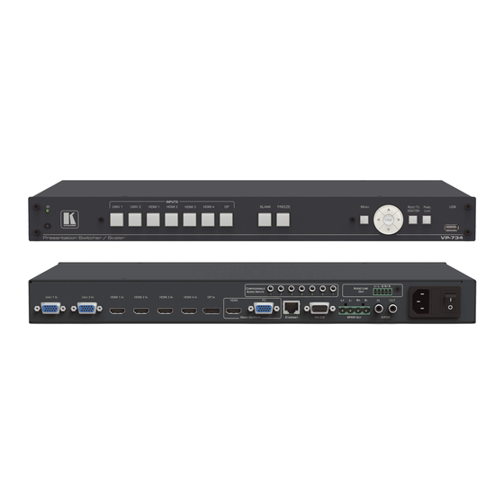
Figure 1: VP-734 Presentation Switcher/ Scaler Front Panel Feature Function IR Receiver Receives signals from the remote control transmitter Lights red when the unit accepts IR remote commands UNIV. Press to select the composite video / s-Video / component video source (configured via the OSD menu, see Section 7.1) -
Page 13: Figure 2: Vp-734 Presentation Switcher/ Scaler Rear Panel
Figure 2: VP-734 Presentation Switcher/ Scaler Rear Panel Feature Function UNIV 1 IN 15-pin HD Connector Connect to the universal source (as computer graphics, composite video, s-Video or component video), from 1 to 2 HDMI 1 IN Connector Connect to the HDMI 1 source (from 1 to 4) -
Page 14: Installing In A Rack
Installing in a Rack This section provides instructions for rack mounting the unit. VP-734 - Installing in a Rack... -
Page 15: Connecting The Vp-734
Connecting the VP-734 Always switch off the power to each device before connecting it to your VP-734. After connecting your VP-734, connect its power and then switch on the power to each device. To connect the VP-734 as illustrated in the example in... - Page 16 We recommend that you use only the power cord that is supplied with this machine If required, connect: A PC via RS-232, see Section 5.2 The ETHERNET port, see Section 5.4 The USB connector, audio sources and acceptors, and power cord are not shown in Figure VP-734 - Connecting the VP-734...
-
Page 17: Figure 3: Connecting To The Vp-734 Rear Panel
Figure 3: Connecting to the VP-734 Rear Panel VP-734 - Connecting the VP-734... -
Page 18: Universal Connector Pinout
Note that PINs 5, 6, 7, 8 and 10 are GND Connecting to the VP-734 via RS-232 You can connect to the VP-734 via an RS-232 connection using, for example, a PC. Note that a null-modem adapter/connection is not required. -
Page 19: Connecting The Balanced/Unbalanced Stereo Audio Output
5.4.1 Connecting the Ethernet Port Directly to a PC You can connect the Ethernet port of the VP-734 directly to the Ethernet port on your PC using a crossover cable with RJ-45 connectors. This type of connection is recommended for identifying the VP-734 with the factory configured default IP address. -
Page 20: Figure 7: Local Area Connection Properties Window
Highlight either Internet Protocol Version 6 (TCP/IPv6) or Internet Protocol Version 4 (TCP/IPv4) depending on the requirements of your IT system. Click Properties. The Internet Protocol Properties window relevant to your IT system appears as shown in Figure 8 Figure VP-734 - Connecting the VP-734... -
Page 21: Figure 8: Internet Protocol Version 4 Properties Window
Figure 8: Internet Protocol Version 4 Properties Window Figure 9: Internet Protocol Version 6 Properties Window VP-734 - Connecting the VP-734... -
Page 22: Figure 10: Internet Protocol Properties Window
Click Close. 5.4.2 Connecting the Ethernet Port via a Network Hub or Switch You can connect the Ethernet port of the VP-734 to the Ethernet port on a network hub or using a straight-through cable with RJ-45 connectors. 5.4.3 Control Configuration via the Ethernet Port To control several units via Ethernet, connect the Master unit (Device 1) via the Ethernet port to the Ethernet port of your PC. -
Page 23: Presentation Switcher / Scaler Buttons
When the front panel is locked, control is still available via RS-232 and/or the Ethernet. To lock the VP-734, Press and hold the PANEL LOCK button on the front panel. The front panel is locked and the PANEL LOCK button is illuminated. Pressing any... -
Page 24: The Infrared Remote Control Transmitter
The Infrared Remote Control Transmitter You can control the VP-734 remotely from the infrared remote control transmitter which is powered by two AAA size 1.5V DC batteries. The IR remote control transmitter has a range of up to 15 meters and delivers instantaneous results... -
Page 25: Configuring The Vp-734 Via The Osd Menu Screens
Screens The VP-734 uses an on-screen display (OSD) menu for system configuration. The menu appears as an overlay over any images that are output from the VP-734. There are seven sub-menus that are used to configure the VP-734. You can activate and navigate these menus from the front panel buttons, or from the IR remote control. -
Page 26: The Input Screen
We recommend that you update the Hpos, Vpos, Frequency and Phase values (in the Fine-tune OSD menu) only after Auto Image is complete (if necessary). Enabled for VGA VP-734 - Configuring the VP-734 via the OSD MENU Screens... -
Page 27: The Picture Screen
Mosquito NR – Set the Mosquito noise reduction level: Off, Low, Medium, High Enabled for analog inputs only Set the Block NR level: Off, On Enabled for analog inputs only VP-734 - Configuring the VP-734 via the OSD MENU Screens... -
Page 28: The Output Screen
100% 325%, 350%, 375%, 400% or click custom to set the custom zoom and enable Zoom H-Pan and Zoom V-Pan Positioning Set H_Start, H_End, H_Position, H_Size, V_Start, V_End, V_Position, V_Size VP-734 - Configuring the VP-734 via the OSD MENU Screens... - Page 29 You can configure the aspect ratio of any output image to fit your application. The VP-734 offers six different aspect ratio settings: Best Fit, Letterbox, Follow Output, Virtual Wide, Follow Input, and Custom. Here is how each of these settings works.
-
Page 30: The Audio Screen
Video in the Input Source menu. When Off selecting a different video signal will not change the audio setting and it can be selected via the Input Source menu separately VP-734 - Configuring the VP-734 via the OSD MENU Screens... -
Page 31: The Setup Screen
Seamless switching is not possible when working in the Frame Lock mode unless all sources are frame synchronized If VP-734 can lock the input then the output will follow If VP-734 cannot lock the input, then the output will not change. - Page 32 When changing the output resolution (not including Native HDMI and Custom 1 to 4), if the new output resolution can be locked, VP-734 locks it. If not, it will be unlocked When changing the output resolution to Native, HDMI or...
- Page 33 3. Click Logo Download item. The BMP image appears 4. Select the BMP file and press the Enter button When Custom is selected in the Logo item menu this logo will appear after powering up the device VP-734 - Configuring the VP-734 via the OSD MENU Screens...
- Page 34 VP-734 When selecting Logo you need to download the Txtlogo.BMP file to the USB and connect it to the VP-734 Firmware For factory use Default Download Path VP-734 - Configuring the VP-734 via the OSD MENU Screens...
-
Page 35: Figure 18: Text Overlay Application Screen
Using Text Overlay The text overlay feature is accessed via the Application Program (AP). Running this AP with the PC connected to the VP-734 lets you display text over the screen, with features including text color and speed, transparency, text position and repetition. - Page 36 When selected, set the COM port and Baud Rate (9600) to connect via the RS-232 connector IP Address When selected Set the IP address of the device and the port Indicates whether there is a valid connection to the VP-734 Current Status Scrolling Mode Area Speed Dropdown Box...
- Page 37 Vertical active start point Vertical active region Vertical polarity OCLK Output clock Save Save setup Get Current Import the values of the currently selected output resolution into the User Mode Setting VP-734 - Configuring the VP-734 via the OSD MENU Screens...
-
Page 38: Figure 19: Active Video Functions
Figure 19 illustrates horizontal and vertical sync pulse width, timing and active video area for a typical frame of video. Figure 19: Active Video Functions VP-734 - Configuring the VP-734 via the OSD MENU Screens... - Page 39 The Maximum Volume Limit Screen Set the maximum output volume from -100 to 24 (default = 24). Doing this allows you to limit the maximum volume level that the user can set. VP-734 - Configuring the VP-734 via the OSD MENU Screens...
-
Page 40: The Info Screen
The Info Screen From the Information screen (see Figure 20), you can verify the Source, Output, Sync Mode, firmware version, Dynamic or static IP. Figure 20: Information Screen VP-734 - Configuring the VP-734 via the OSD MENU Screens... -
Page 41: Firmware Upgrade
Kramer Web site at http://www.kramerelectronics.com/support/downloads.asp You can upgrade the VP-734 via the VP Download tool, which can be downloaded from our Web site. After downloading this upgrade tool: Connect the VP-734 to your PC via the Ethernet. -
Page 42: Using The Embedded Web Pages
Using the Embedded Web Pages The Web pages let you control the VP-734 via the Ethernet. The Web pages include all the OSD items and more, and are accessed using a Web browser and an Ethernet connection. Note that the Web page features are described in more detail in the OSD... -
Page 43: Figure 22: Using The Embedded Web Pages - The Authentication Window
The EDID management page (see Section 9.8) The Advanced Settings page (see Section 9.9) The Custom Resolutions page (see Section 9.10) The Security page (see Section 9.11) The About page (see Section 9.12) VP-734 - Using the Embedded Web Pages... -
Page 44: The Routing & Scaling Page
Scaling page selected and below a list of all the other available Web pages. Figure 23: The Routing & Scaling Page with Web page list on the left Click the arrow to hide the Web pages list on the left: VP-734 - Using the Embedded Web Pages... -
Page 45: Figure 24: The Routing & Scaling Page
The Routing & Scaling main area shows a depiction of the display. Click and move the mouse to move the image and size by moving the right and bottom edges of the image Figure 25: The Routing & Scaling Page VP-734 - Using the Embedded Web Pages... -
Page 46: Figure 26: The Routing & Scaling Page - Selecting The Output Resolution
For example, in Figure 27 HDMI 2 input is selected and appears green on the list. Figure 27: The Routing & Scaling Page – Input Selection VP-734 - Using the Embedded Web Pages... -
Page 47: Figure 28: The Routing & Scaling Page - Program Lower Buttons Bar
The lower buttons bar lets you perform quick and easy setups: Figure 28: The Routing & Scaling Page – Program Lower Buttons Bar Button Function Select freeze and/or blank effects Select a pattern Lock aspect ratio VP-734 - Using the Embedded Web Pages... -
Page 48: Figure 29: The Routing & Scaling Page - Storing And Recalling A Preset
The volume audio slider appears on the right side of the page and can be toggled to mute and unmute, if required (see Section 9.6). Figure 30: The Routing & Scaling Page – Muting the Audio Level VP-734 - Using the Embedded Web Pages... -
Page 49: The Device Settings Page
The Device Settings Page The Device Settings window (in Figure 32) lets you set the device name, change the Ethernet parameters, perform factory reset and view the information data. Figure 32: The Device Settings Page VP-734 - Using the Embedded Web Pages... -
Page 50: Figure 33: The Device Settings Page - The Information Window
After changing the IP number, you need to reload the Web page with the new IP number After changing the Subnet mask you need to turn the VP-734 power off and then on again 9.3.2 The Information Window... -
Page 51: The Input Settings Page
Set the priority for auto-switching of the selected input Source type (UNIV) Set the type of the analog video source (VGA/Component/YC/Video), disabled if the selected input is not UNIV, see Section 7.1 HDCP (HDMI & Set to ON or OFF DisplayPort) VP-734 - Using the Embedded Web Pages... - Page 52 N/NTSC 4.43/SECAM/PAL-60 (for YC and video inputs), see Section 7.1 Auto Image Section 7.1 Input Volume Set the selected input volume You can set the source label by typing the label name and saving it: VP-734 - Using the Embedded Web Pages...
-
Page 53: The Output Settings Page
Set the HDMI1 output type to Auto, HDMI or DVI Test Patterns Set the test pattern to Colorbar, SMPTE, Greyscale, Picture Border, Multiburst, Ramps, H-pattern, Setup, or set to Off Output Volume Set the output audio level VP-734 - Using the Embedded Web Pages... -
Page 54: The Audio Settings Page
Select the delay to dynamic, User Define or Off. Set the delay time (in milliseconds) Set to Off or On Audio-Follow-Video Set the selected input audio level Input Volume Output Volume Set the output volume VP-734 - Using the Embedded Web Pages... -
Page 55: The Miscellaneous Video Settings Page
Select Seamless switching or Fast switching, see Section 7.5 Frame Latency Set to Best Quality or Fast, see Section 7.5 Hot Plugs Set Hot Plug On or Off for HDMI1 to HDMI 4 and DisplayPort, see Section 7.5 VP-734 - Using the Embedded Web Pages... -
Page 56: The Edid Management Page
The EDID page lets you read the EDID from any of the outputs (HDMI 1 and VGA), from a list of default resolutions or from a file in your PC (Browse). The selected EDID can be copied to a selected input. Figure 39: The EDID Page VP-734 - Using the Embedded Web Pages... -
Page 57: Figure 40: The Edid Page - Copying The Edid From
Figure 41: The EDID Page – Selecting a Resolution to copy to an Input To copy the EDID from the output select the output and the input to which you want to copy the EDID and click the Copy button. The EDID is copied: VP-734 - Using the Embedded Web Pages... -
Page 58: Figure 42: The Edid Page - Copying From An Output
Figure 42: The EDID Page – Copying from an Output VP-734 - Using the Embedded Web Pages... -
Page 59: The Advanced Settings Page
Select ON (to save the lock status when the machine is powered on power down down) or Off Lock panel status Select ON or OFF (to use the SOURCE buttons on the front panel disables input selection even when the lock button is on) VP-734 - Using the Embedded Web Pages... -
Page 60: The Custom Resolutions Page
9.11 The Security Page Set Activate to ON to enter the Web page with a password and change the password, if required. Click Change to save the changes Figure 45: The Security Page VP-734 - Using the Embedded Web Pages... -
Page 61: The About Page
9.12 The About Page The VP-734 About page lets you view the Web page version and Kramer Electronics Ltd details. Figure 46: The About Page VP-734 - Using the Embedded Web Pages... -
Page 62: Technical Specifications
19" (W), 9.3" (D) 1U (H) rack mountable WEIGHT: 2.45kg (5.4lbs) approx. rack “ears”, IR remote control, power cord, 2 C-GM/3RVF-1 INCLUDED ACCESSORIES: Specifications are subject to change without notice For the most updated resolution list, go to our Web site at http://www.kramerelectronics.com VP-734 - Technical Specifications... -
Page 63: Default Communication Parameters
VESA Reduced 800x600 VESA 1366x768 VESA Blanking 832x624 Mac16 1366x768 VESA Reduced 1024x768 VESA 1440x900 VESA Blanking 1024x768 VESA 1440x900 VESA 1024x768 VESA 1400x1050 VESA 1024x768 Mac19 1400x1050 VESA 1024x768 VESA 1600x900 VESA 1024x800 1600x1200 VESA VP-734 - Technical Specifications... - Page 64 VESA 800x600 VESA 1280x1024 VESA 800x600 VESA 1280x1024 800x600 VESA 1280x1024 VESA Reduced 800x600 VESA 1366x768 VESA Blanking 800x600 VESA 1366x768 VESA Reduced 832x624 Mac16 1440x900 VESA Blanking 1024x768 VESA 1440x900 VESA 1024x768 VESA 1400x1050 VESA VP-734 - Technical Specifications...
- Page 65 Technical Specifications of the HDMI Input Signal (for RGB or YUV Colorspace) Resolution Vertical Frequency Notes Resolution Vertical Frequency Notes (Hz) (Hz) 1080i YPbPr 720p YPbPr 1080i YPbPr 480i YPbPr 1080p YPbPr 480p YPbPr 1080p YPbPr 576i YPbPr 1080P YPbPr 576p YPbPr 720p YPbPr VP-734 - Technical Specifications...
-
Page 66: Tables Of Supported Output Resolutions
1280x768 480p 1280x768 VESA 576p 1280x800 VESA 1080p 1280x1024 1080p Comp/YPbPr 1280x1024 VESA 480p 59.94 1280x1024 VESA 720p 59.94 1366x768 1080i 59.94 1366x768 VESA 1080p 23.98 1400x1050 1080p 1400x1050 VESA 1080p 29.97 1600x900 VESA 1080p 59.94 VP-734 - Technical Specifications... - Page 67 VESA 576p 1280x1024 VESA 1080p 1366x768 1080p 1366x768 VESA 480p 59.94 1400x1050 720p 59.94 1400x1050 VESA 1080i 59.94 1600x900 VESA 1080p 23.98 1600x1200 1080p 1600x1200 VESA 1080p 29.97 1920x1080 VESA 1080p 59.94 VESA Reduced 1920x1200 Blanking VP-734 - Technical Specifications...
-
Page 68: Vp-734 Communication Protocol
Example: get current Input 1 Source Type Send: Y113CR Reply: Z1103CRLF > Definition: : ASCII Code 0x20 CR: Ascii Code 0x0D CRLF : Ascii Code 0x0D+0x0A Go to http://www.kramerelectronics.com/support/product_downloads.asp check for the latest VP-734 communication protocol. VP-734 - VP-734 Communication Protocol... -
Page 69: Command List
6: DP 1 0: Off Auto Switch Input Source 1: On 0: VGA Input 1 Source Type 1: Component 2: YC 3: Video 0: VGA Input 2 Source Type 1: Component 2: YC 3: Video VP-734 - VP-734 Communication Protocol... - Page 70 1: Native VGA 2: 640x480x60Hz 3: 640x480x75Hz 4: 800x600x50Hz 5: 800x600x60Hz 6: 800x600x75Hz 7: 1024x768x50Hz 8: 1024x768x60Hz 9: 1024x768x75Hz 10: 1280x768x50Hz 11: 1280x768x60Hz 12: 1280x720x60Hz 13: 1280x800x60Hz 14: 1280x1024x50Hz 15: 1280x1024x60Hz 16: 1280x1024x75Hz 17: 1366x768x50Hz VP-734 - VP-734 Communication Protocol...
- Page 71 Aspect Ratio V Pan -8 ~ 8 Aspect Ratio H Zoom -8 ~ 8 Aspect Ratio V Zoom 0: 100% Zoom 1: 150% 2: 200% 3: 225% 4: 250% 5: 275% 6: 300% 7: 325% VP-734 - VP-734 Communication Protocol...
- Page 72 8: Embedded 0: Off Audio Follow Video 1: On 0: Profile 1 Save 1: Profile 2 2: Profile 3 3: Profile 4 4: Profile 5 5: Profile 6 6: Profile 7 7: Profile 8 8: USB VP-734 - VP-734 Communication Protocol...
- Page 73 7 : Off 0: Off Input HDMI1 Hot Plug 1: On 0: Off Input HDMI2 Hot Plug 1: On 0: Off Input HDMI3 Hot Plug 1: On 0: Off Input HDMI4 Hot Plug 1: On VP-734 - VP-734 Communication Protocol...
- Page 74 Advanced Misc – Logo 3: Bottom Left Advanced Misc –Blank Color 4: Bottom Right 0: 5 sec OSD Timeout 1: 10 sec 2: 20 sec 3: 30 sec 4: 60 sec 5: 90 sec 6: Off VP-734 - VP-734 Communication Protocol...
- Page 75 0: Off Text Overlay 1: Text Requirements: 1. Text: you need to have TextOvl.ini in USB disc and connect it to VP-734 2: Logo 2. Logo: you need to have Txtlogo.bmp in USB disc and connect it to VP-734 0: Custom1...
- Page 76 11 : 1920x1200x60Hz (RB) 12 : 720Px60Hz 13 : 720Px60Hz 14 : 1080Px60Hz 15 : 1080px60Hz 16 : 2048x1080x50Hz 17 : 2048x1080x60Hz 0 : Default Input EDID HDMI2 1 : Copy HDMI Out 2 : User Define VP-734 - VP-734 Communication Protocol...
- Page 77 1: Copy HDMI Out 2: User Define Default (1920x1080x60Hz) Input EDID HDMI4 Modeline 1: 1024x768x60Hz 2: 1280x800x60Hz 3: 1280x1024x60Hz 4: 1366x768x60Hz 5: 1440x900x60Hz 6: 1400x1050x60Hz 7: 1600x900x60Hz 8: 1600x1200x60Hz 9: 1680x1050x60Hz 10: 1920x1080x60Hz 11: 1920x1200x60Hz (RB) VP-734 - VP-734 Communication Protocol...
- Page 78 Input EDID UNIV2 1: Copy PC Out 2: User Define 0: Default (1920x1200x60Hz) Input EDID UNIV2 Modeline 1: 1024x768x60Hz 2: 1280x800x60Hz 3: 1280x1024x60Hz 4: 1366x4768x60Hz 5: 1440x900x60Hz 6: 1400x1050x60Hz 7: 1600x900x60Hz 8: 1600x1200x60Hz 9: 1680x1050x60Hz VP-734 - VP-734 Communication Protocol...
- Page 79 36: 1440x900x60Hz (RB) 37: 1440x900x60Hz 38: 1400x1050x60Hz 39: 1400x1050x75Hz 40: 1600x900x60Hz (RB) 41: 1600x1200x60Hz 42: 1680x1050x60Hz (RB) 43: 1680x1050x60Hz 44: 1920x1080x60Hz 45: 1920x1200x60Hz (RB) 46: 2048x1080x50Hz 47: 2048x1080x60Hz 100: Custom1 101: Custom2 102: Custom3 103: Custom4 VP-734 - VP-734 Communication Protocol...
- Page 80 16: 1280x1024x75Hz 17: 1366x768x50Hz 18: 1366x768x60Hz 19: 1400x1050x50Hz 20: 1400x1050x60Hz 21: 1600x900x60Hz (RB) 22: 1600x1200x50Hz 23: 1600x1200x60Hz 24: 1680x1050x60Hz 25: 1920x1080x60Hz 26: 1920x1200x60Hz (RB) 27: 2048x1080x50Hz 28: 2048x1080x60Hz 100: 480P60 101: 576P50 102: 720P50 103: 720P60 VP-734 - VP-734 Communication Protocol...
- Page 81 2 : HDMI 1 bit 3 : HDMI 2 bit 4 : HDMI 3 bit 5 : HDMI 4 bit 6 : DP 1 bit 8 : Blank bit 9 : Freeze bit 12 : Panel Lock VP-734 - VP-734 Communication Protocol...
-
Page 83: Safety Warning
SAFETY WARNING Disconnect the unit from the power supply before opening and servicing For the latest information on our products and a list of Kramer distributors, visit our Web site where updates to this user manual may be found. We welcome your questions, comments, and feedback.
Need help?
Do you have a question about the VP-734 and is the answer not in the manual?
Questions and answers