Table of Contents
Advertisement
Great Planes
®
Model Manufacturing Co. guarantees this kit to be free from defects in both material and workmanship at the date of
purchase. This warranty does not cover any component parts damaged by use or modification. In no case shall Great Planes' liability
exceed the original cost of the purchased kit. Further, Great Planes reserves the right to change or modify this warranty without
notice.
In that Great Planes has no control over the final assembly or material used for final assembly, no liability shall be assumed nor accepted
for any damage resulting from the use by the user of the final user-assembled product. By the act of using the user-assembled product,
the user accepts all resulting liability.
If the buyer is not prepared to accept the liability associated with the use of this product, the buyer is advised to return this
kit immediately in new and unused condition to the place of purchase.
While this kit has been flight tested to exceed normal use, if the plane will be used for extremely high stress flying, such as racing, the
modeler is responsible for taking steps to reinforce the high stress points.
READ THROUGH THIS MANUAL BEFORE
STARTING CONSTRUCTION. IT CONTAINS
IMPORTANT WARNINGS AND INSTRUCTIONS
CONCERNING THE ASSEMBLY AND USE OF
THIS MODEL.
© Copyright 1999
INSTRUCTION MANUAL
Almost Ready-to-Fly
WARRANTY
P.O. Box 788
Urbana, IL 61803
www.greatplanes.com
(217) 398-8970
Manual GPMZ0213 for Kit GPMA1245 V1.0
Advertisement
Table of Contents

Related Manuals for GREAT PLANES AT-6 Texan


Summary of Contents for GREAT PLANES AT-6 Texan
-
Page 1: Instruction Manual
In that Great Planes has no control over the final assembly or material used for final assembly, no liability shall be assumed nor accepted for any damage resulting from the use by the user of the final user-assembled product. By the act of using the user-assembled product, the user accepts all resulting liability. -
Page 2: Table Of Contents
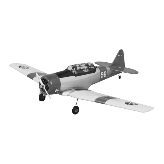
Radio Installation ......8 The Great Planes AT-6 ARF is a high performance sport Throttle Pushrod Installation . -
Page 3: Decisions You Must Make
Required Accessories Optional Retract Items Items in parentheses (GPMQ4243) are suggested part numbers recognized by distributors and hobby shops and are listed for your ordering convenience. GPM is the Great Planes ® brand, Hobbico Mechanical Retracts Main (HCAP4010) TOP is the Top Flite ®... -
Page 4: Parts List
Key # Description 13 ..Fin ....1 Replacement Parts 1 ..Fuselage ... . . 1 14 ..Right Aileron Servo Hatch. -
Page 5: Wing Assembly
joiner is desirable. If the joiner does not fit properly, lightly WING ASSEMBLY sand any uneven surfaces from the joiner edges and sides. Note: The wing joiners are tapered to fit into the wing panels. Make sure the angles are lined up to provide the correct alignment of the wing panels and center section. -
Page 6: Install The Tail Components
distance. Measure from the same point to the opposite wing tip, and compare it to the first measurement. If the measurements are not the same, adjust the wing and remeasure until they are equal. Place a mark on the wing and fuselage so it can be repositioned accurately for the following steps. -
Page 7: Engine Installation
C. Pack the tail gear wire slot in the fuselage with epoxy. To insure that you have working time, we recommend using 30-minute epoxy. Rejoin the rudder to the fin using the hinges. Use a tissue dampened with alcohol to wipe away excess epoxy before it cures. -
Page 8: Radio Installation
6. Position the engine on the engine mount rails so the propeller thrust washer (or spinner backplate) is 4-1/2” 2. Connect the marks on the firewall to locate the center (114mm) ahead of the firewall. Use a Great Planes Dead of the firewall. Center ™... - Page 9 - three servos, the receiver, switch and aileron servos. battery as shown in the photo. We added a Great Planes Switch Mount & Change Jack (GPMM1000, not included) for convenience and ease of use at the field, installed on the side of the fuselage.
- Page 10 9. Use a 3/16” (4.7mm) drill bit to chamfer the holes for easier installation of the pushrod tubes. Servo Horn 2-56 (.074") Pushrod Wire FasLink 1/16" 7. Two 2-56 x 6” Threaded End Rods are supplied to make the Aileron pushrods. Thread a nylon Clevis onto a pushrod about 14 turns and add a Silicone Retainer to the clevis.
- Page 11 slide easily into the tube. Screw a nylon clevis on the pushrod about 14 turns and add a silicone retainer to the clevis. Trim the bottom hole from a control horn as shown in the photo and attach the clevis to the outermost hole. HINGE LINE 17.
-
Page 12: Throttle Pushrod Installation
THROTTLE PUSHROD INSTALLATION FINAL ASSEMBLY The following steps cover fitting the cowl to an O.S. engine using a Slimline muffler. 1. Install a Brass Screw-lock Pushrod Connector with the 4-40 x 1/8” Cap Screw on the throttle servo horn. Snap the Nylon Retainer onto the screw-lock pushrod connector 1. -
Page 13: Finish The Cockpit
5. Drill the locations for the cowl mounting screws using a FINISH THE COCKPIT 1/8” (3mm) drill bit. Mark the locations on the cowl mounting blocks. Use a 3/32” (2.4mm) drill bit to drill into the blocks. Install the screws and then remove them. Wick thin CA into the holes to harden the wood, which will prevent the screws from stripping the underlying wood. -
Page 14: Wheel Installation
(28mm right, 28mm left) (16mm right, 16mm left) One leading cause of crashes is flying an airplane with its control throws set differently from those recommended in the instructions. The Great Planes AccuThrow (GPMR2405) ™ lets you quickly and easily measure actual throws first, so you can make necessary corrections before you fly. -
Page 15: Balance Your Model Laterally
1. Remove the covering from the opening in the 6. Install the retract servo into the center section using center section for the retract mechanism. Test fit the retract two hardwood blocks. The servo must be mounted as low into the wing. Remove the balsa sheeting from the wing to as possible in the wing. -
Page 16: Balance Your Model (Cg)
Balance when assembling the fuel tank. your AT-6 using a Great Planes C.G. Machine™ Airplane Balancer (GPMR2400) for the most accurate results. This is 2. Wrap the tank with 1/4” foam rubber (HCAQ1000) the balance point at which your model should balance for your secured with a couple of rubber bands. -
Page 17: Secure The Pushrods
We use a Top Flite Precision Magnetic Prop Balancer ™ (TOPQ5700) in the workshop and keep a Great Planes Fingertip Balancer (GPMQ5000) in our flight box. Find A Safe Place to Fly Since you have chosen the AT-6 ARF, we assume that you are an experienced modeler. -
Page 18: Ground Check The Model
Ground Check the Model Make all engine adjustments from behind the rotating Inspect your radio installation and confirm that all the control propeller. surfaces respond correctly to the transmitter inputs. The engine operation must also be checked by confirming that The engine gets hot! Do not touch it during or right after the engine idles reliably, transitions smoothly and rapidly to operation. -
Page 19: Flying
The Great Planes AT-6 ARF is a great-flying plane that flies model to climb at a shallow angle (do not yank the model smoothly and predictably. - Page 20 BUILDING NOTES Kit Purchased Date:________________________ Date Construction Finished: _________________ Where Purchased:_________________________ Finished Weight: __________________________ Date Construction Started: __________________ Date of First Flight: ________________________ FLIGHT LOG...
Need help?
Do you have a question about the AT-6 Texan and is the answer not in the manual?
Questions and answers