Rangemaster Classic Deluxe 100 User's Manual & Installation Instructions
Induction g5
Hide thumbs
Also See for Classic Deluxe 100:
- User's manual & installation instructions (48 pages) ,
- User's manual & installation instructions (40 pages) ,
- User's manual & installation instructions (36 pages)

Related Manuals for Rangemaster Classic Deluxe 100


Summary of Contents for Rangemaster Classic Deluxe 100
-
Page 1: User Guide
Britain’s No.1 Range Cooker USER GUIDE & INSTALLATION INSTRUCTIONS Classic Deluxe 100 Induction G5 Professional+ 100 Induction G5 Professional Deluxe 100 Induction G5 Hi-LITE 100 Induction G5... - Page 2 We offer cookware to work perfectly with all fuel types manufactured by Rangemaster, including induction hobs. You can be assured of functionality with style, as well as the quality and meticulous attention to detail you expect from the pioneers of range cooking.
-
Page 3: Table Of Contents
Contents Before You Start... Troubleshooting Installation and Maintenance Installation Peculiar Smells Dear Installer Ventilation Safety Requirements and Regulations Personal Safety Provision of Ventilation Hob Care Location of Cooker Cooker Care Positioning the Cooker Cooker Overview Moving the Cooker The Hob Repositioning the Cooker Following Connection The Glide-out Grill... -
Page 5: Before You Start
1. Before You Start... This User Guide covers a number of different models. Ventilation Although some of the illustrations will look different to CAUTION: The use of a cooking appliance results in your particular model the functions will be the same. We the production of heat and moisture in the room in hope the meaning is clear. - Page 6 Always be certain that the controls are in the OFF position Fig.1-1 when the oven is not in use, and before attempting to clean the cooker. Take care when touching the marked cooking areas of the hob. When the oven is on, DO NOT leave the oven door open for longer than necessary, otherwise the ArtNo.324-0001 Steam burst control knobs may become very hot.
-
Page 7: Hob Care
DO NOT use water on grease fires and never pick Fig.1-2 up a flaming pan. Turn off the controls and then ArtNo.312-0001 Not cooking surface smother a flaming pan on a surface unit by covering the pan completely with a well fitting lid or baking tray. -
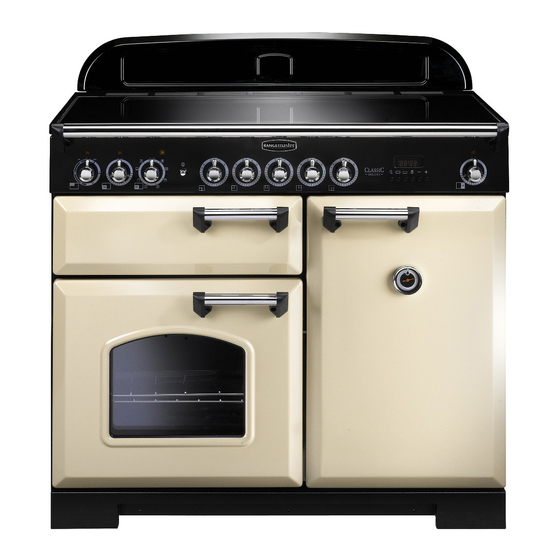
Page 8: Cooker Overview
2. Cooker Overview Fig.2-1 The 100 induction cooker (Fig.2-1) has the following features: Fig.2-2 5 induction cooking zones A control panel A separate glide-out grill A main programmable multi-function oven (Classic Deluxe & Professional Deluxe) or fan oven (Professional+ & Hi-LITE) Tall fan oven The Hob Use only pans that are suitable for induction hobs. - Page 9 Never use a round-bottomed wok, even with a stand. Fig.2-3 The very best pans have bases that are very slightly curved up when cold (Fig.2-3). If you hold a ruler across the bottom you will see a small gap in the middle. When they heat up the metal expands and lies flat on the cooking surface.
-
Page 10: Child Lock
Residual Heat Indicator, H Automatic heat-up time at Power Level 100% (min:sec) After use, a cooking zone will remain hot for a while as heat dissipates. When a cooking zone is switched off the residual 0:48 heat indicator symbol [H ], will appear in the display. This 2:24 shows that the cooking zone temperature is above 60 °C and may still cause burns. - Page 11 Low Temperature Setting, L1/L2 Maximum Operating Time Power Level Each cooking area is equipped with 2 low temperature settings: 2 hours L1 and L2 • L1 will maintain a temperature of about 40 °C – ideal for 6 hours gently melting butter or chocolate. 6 hours • L2 will maintain a temperature of about 90 °C –...
-
Page 12: The Glide-Out Grill
The Glide-out Grill Fig.2-9 CAUTION: This appliance is for cooking purposes only. It must not be used for other purposes, for example room heating. Accessible parts may be hot when the grill is in use. Young children should be kept away. Open the door and pull the grill pan carriage forward using the handle (Fig.2-9). - Page 13 Fanned Grilling Multi-function Ovens This function operates the fan whilst the top element Multi-function ovens have an oven fan and oven fan element, is on. It produces a more even, less fierce heat than a as well as two extra heating elements. One element is in conventional grill.
-
Page 14: Operating The Ovens
Base Heat Fig.2-12 This function uses the base element only. It will crisp ArtNo.235-0003 - Classic DL MF knobs up your pizza or quiche base or finish off cooking the base of a pastry case on a lower shelf. It is also a gentle heat, good for slow cooking of casseroles in the middle of the oven or for plate warming. -
Page 15: Main Oven Light
Main Oven Light Fig.2-15 Press the button to turn the light on (Fig.2-15). If the oven light fails, turn off the power supply before changing the ArtNo.320-0017 bulb. See the ‘Troubleshooting’ section for details on how to Main oven light change the bulb. -
Page 16: The Clock
The Clock Fig.2-17 ArtNo.300-0004 2-button clock annotated You can use the clock to turn the left-hand oven on and off. The clock must be set to the time of day before the oven will work. Note: When using the timer functions, first set the clock as required before setting the oven temperature and selecting the oven function (multi-function ovens only). - Page 17 Turn the Adjusting knob to set the ‘cooking time’ you need Fig.2-23 ArtNo.301-0010 2BC (Fig.2-23). Setting the cooking time Turn the Timer knob to the [ ] position. The display will show the current time of day plus the ‘cook time’ you just set. Use the Adjusting knob to set the ‘stop time’...
- Page 18 The 6-button Clock (Classic Deluxe) Fig.2-30 Setting the Time of Day The 6-button LCD clock is shown in Fig.2-30. When the clock is first connected the display flashes ( 0.00) and ( alternately. ArtNo.302-0002 - 6BC annotated Press and hold both the [] and [] buttons down (Fig.2-31).
- Page 19 AUTO is Showing but You Want to Reset to Manual Fig.2-40 Fig.2-41 Cooking To return to manual cooking from any automatic setting, the ‘cook period’ must be cancelled. Press and hold the [] button and then press the [ –] button until the display reads ArtNo.302-0009 - Activating ( 0.00).
-
Page 20: Accessories
Accessories Fig.2-45 Flat shelf Oven Shelves – Left-hand (Main) Oven Shelf guard In addition to the flat shelf your cooker is supplied with a drop shelf (Fig.2-45). The drop shelf increases the possibilities for oven shelf spacing. Front Please note: The Hi-LITE does not have a drop shelf, but is supplied with two flat cooking shelves. -
Page 21: Cooking Tips
3. Cooking Tips Using Your Induction Cooker General Oven Tips If you have not used an induction cooker before please be The wire shelves should always be pushed firmly to the back aware of the following: of the oven. • Make sure that the pans you have or buy are suitable Baking trays with food cooking on them should be placed for use on the induction hob. -
Page 22: Cooking Table
4. Cooking Table DocNo.031-0004 - Cooking table - electric & fan single cavity The oven control settings and cooking times given in the table below are intended to be used Top (T) AS A GUIDE ONLY. Individual tastes may require the temperature to be altered to provide a preferred result. -
Page 23: Cleaning Your Cooker
DocNo.043-0004 - Cleaning - IN 90 - GO grill w glass door EVENS 5. Cleaning Your Cooker Isolate the electricity supply before carrying out any major Fig.5-1 cleaning. Allow the cooker to cool. NEVER use paint solvents, washing soda, caustic cleaners, biological powders, bleach, chlorine based bleach cleaners, coarse abrasives or salt. -
Page 24: Glide-Out Grill
Glide-out Grill Fig.5-2 The grill pan and trivet should be washed in hot soapy water. Alternatively, the grill pan can be washed in a dishwasher. After grilling meats or any foods that soil, leave to soak for a few minutes immediately after use. Stubborn particles may be removed from the trivet using a nylon brush. -
Page 25: Ovens
Glass Fronted Door Panels Fig.5-7 DO NOT use harsh abrasive cleaners or sharp metal scrapers to clean the oven door glass since they can scratch the surface, which may result in shattering of the glass. The oven door front panels can be taken off so that the glass panels can be cleaned. -
Page 26: Cleaning Table
Cleaning Table Cleaners listed (Table 5-1) are available from supermarkets or electrical retailers as stated. For enamelled surfaces use a cleaner that is approved for use on vitreous enamel. Regular cleaning is recommended. For easier cleaning, wipe up any spillages immediately. Hotplate Part Finish... -
Page 27: Troubleshooting
6. Troubleshooting Interference with and repairs to the hob MUST NOT The hob will not switch on be carried out by unqualified persons. Do not try Has the wiring system in the house blown a fuse or to repair the hob as this may result in injury and tripped an RCD? damage to the hob. - Page 28 Grill not cooking properly The oven is not cooking evenly Are you using the pan and trivet supplied with the Do not use a baking tray with dimensions larger than cooker? Is the pan being used on the runners, not the those specified in the section on ‘General Oven Tips’...
- Page 29 The Oven light is not working Fig.6-1 The bulb has probably burnt out. You can buy a replacement bulb (which is not covered under the guarantee) from a good electrical shop. Ask for a 15 W – ArtNo.324-0005 Oven light bulb 230 V lamp, FOR OVENS.
-
Page 30: Installation
INSTALLATION Check the appliance is electrically safe when you have finished. 7. Installation You will need the following equipment to complete the Dear Installer cooker installation satisfactorily: Before you start your installation, please complete the details • Multimeter (for electrical checks). below, so that, if your customer has a problem relating to your installation, they will be able to contact you easily. -
Page 31: Positioning The Cooker
INSTALLATION Check the appliance is electrically safe when you have finished. Positioning the Cooker Fig.7-1 Fig.7-1 and Fig.7-2 show the minimum recommended distance from the cooker to nearby surfaces. 75 mm 75 mm 650 mm The cooker should not be placed on a base. The hotplate surround should be level with, or above, any adjacent work surface. -
Page 32: Repositioning The Cooker Following Connection
INSTALLATION Check the appliance is electrically safe when you have finished. Lowering the Two Rear Rollers Fig.7-5 To adjust the height of the rear of the cooker, first fit a 13 mm spanner or socket wrench onto the hexagonal adjusting nut (Fig.7-5). -
Page 33: Electrical Connection
INSTALLATION Check the appliance is electrically safe when you have finished. Electrical Connection Fig.7-8 The cooker must be installed by a qualified electrician, in accordance with all relevant British Standards/Codes of Practice (in particular BS 7671), or with the relevant national and local regulations. -
Page 34: Final Fitting
INSTALLATION Check the appliance is electrically safe when you have finished. Final Fitting Fig.7-10 Fitting the Handles and Handrail (Classic Deluxe) Remove the 4 mm Allen screws from the doors (Fig.7-10). Fit the door handles and secure using the 4 mm screws. ArtNo.215-0026 - Handle gaskets fixed The handles should be above the fixings. -
Page 35: Circuit Diagrams
8. Circuit Diagrams Oven Circuit Diagram – Classic Deluxe & Professional Deluxe P038434 P095199 w br Legend The connections shown in the circuit diagram are for single-phase. The ratings are for 230 V 50 Hz. Code Description Code Description Code Colour Grill controller Clock Blue... -
Page 36: Oven Circuit Diagram - Professional
Oven Circuit Diagram – Professional+ P095199 P033458 Induction hob connections Legend The connections shown in the circuit diagram are for single-phase. The ratings are for 230 V 50 Hz. Code Description Code Description Code Colour Grill controller Oven light switch Blue Right-hand grill element Oven light... -
Page 37: Circuit Diagram: Fan Oven (Hi-Lite)
Circuit Diagram: Fan Oven (Hi-LITE) P095199 P095199 P095199 Legend The connections shown in the circuit diagram are for single-phase. The ratings are for 230 V 50 Hz. Code Description Code Description Code Colour Illumination board - left-hand side Right-hand oven thermostat Blue Grill front switch Right-hand oven front switch... -
Page 38: Induction Hob Circuit Diagram
Induction Hob Circuit Diagram Earth On terminal block N(6) On terminal block N(4) Induction unit Hob display ArtNo.083-00211 - IN 100 - Circuit diagram - Classic DL- Prof+ hob L(2) L(3) On terminal block w/br Interface w/br w/br board w/br w/br Code Colour Code Description... -
Page 39: Technical Data
9. Technical Data INSTALLER: Please leave these instructions with the user. DATA BADGE LOCATION: Cooker back, serial number repeater badge below door opening. COUNTRIES OF DESTINATION: GB, IE. Connections Electric 230 / 400 V 50 Hz Dimensions Total height Min 905 mm Max 930 mm Total width 994 mm... - Page 40 Notes...
- Page 41 Notes...
- Page 42 Notes...
- Page 43 Gas Safe registered engineer for gas appliances or an approved electrician for electrical models. CONSUMER SERVICE For a competitive quote and to arrange for a Rangemaster approved If you have any product enquiries, or in the event of a problem engineer to attend, call Consumer Services on: 0870 7895107.
- Page 44 Registered in England and Wales. Registration No. 354715 Registered Office: Juno Drive, Leamington Spa, Warwickshire, CV31 3RG Rangemaster continuously seeks improvements in specification, design and production of products and thus, alterations take place periodically. Whilst every effort is made to produce up-to-date literature, this booklet should not be regarded as an infallible guide to...
Need help?
Do you have a question about the Classic Deluxe 100 and is the answer not in the manual?
Questions and answers