Table of Contents
Advertisement
Quick Links
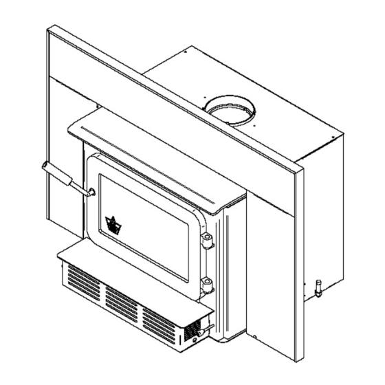
Installation and Operation Manual
XTD 1.9 Insert
US ENVIRONMENTAL PROTECTION
AGENCY PHASE II CERTIFIED
WOOD INSERT
Safety tested according to ULC S628,
UL 737 and UL 1482 Standards
by Intertek Testing Services
www.flame-intl.com
Stove Builder International Inc.
250, rue de Copenhague, St-Augustin-de-Desmaures
(Quebec) Canada G3A 2H3
Tel: (418) 878-3040
Fax: (418) 878-3001
This manual is available for free download on the manufacturer's web site. It is a
copyrighted document. Re-sale is strictly prohibited. The manufacturer may update this
manual from time to time and cannot be responsible for problems, injuries, or damages
arising out of the use of information contained in any manual obtained from unauthorized
sources.
READ AND KEEP THIS MANUAL FOR REFERENCE
45551A
Printed in Canada
16-01-2013
Advertisement
Table of Contents

Subscribe to Our Youtube Channel
Related Manuals for Flame Energy XTD 1.9


Summary of Contents for Flame Energy XTD 1.9
- Page 1 Installation and Operation Manual XTD 1.9 Insert US ENVIRONMENTAL PROTECTION AGENCY PHASE II CERTIFIED WOOD INSERT Safety tested according to ULC S628, UL 737 and UL 1482 Standards by Intertek Testing Services www.flame-intl.com Stove Builder International Inc. 250, rue de Copenhague, St-Augustin-de-Desmaures...
- Page 2 XTD 1.9 Insert Installation and Operation Manual THANK YOU FOR CHOOSING THIS FLAME WOOD INSERT As one of North America’s largest and most respected wood stove and fireplace manufacturers, Stove Builder International takes pride in the quality and performance of all its products.
-
Page 3: Table Of Contents
XTD 1.9 Insert Installation and Operation Manual Table of content PART A - OPERATION AND MAINTENANCE ......... 6 Safety Information ................6 Summary of Operation and Maintenance Cautions and Warnings ......6 General Information ................8 ... - Page 4 XTD 1.9 Insert Installation and Operation Manual Fan Operation ...................... 22 4.5.1 Building Different Fires for Different Needs ............22 Insert Maintenance................25 5.1.1 Cleaning Door Glass ..................25 5.1.2 Door Adjustment ....................26 ...
- Page 5 XTD 1.9 Insert Installation and Operation Manual 9.7.1 Why the Chimney Should Penetrate the Highest Heated Space ...... 47 Supply of Combustion Air ..................47 9.8.1 Air Supply in Conventional Houses ..............48 Appendix 1: Blower Installation ............49 ...
-
Page 6: Part A - Operation And Maintenance
XTD 1.9 Insert Installation and Operation Manual PART A - OPERATION AND MAINTENANCE Please see Part B for installation instructions. 1 Safety Information 1.1 Summary of Operation and Maintenance Cautions and Warnings • OPERATE ONLY WITH DOOR FULLY CLOSED OR FULLY OPEN WITH FIRE SCREEN IN PLACE. - Page 7 XTD 1.9 Insert Installation and Operation Manual • DO NOT BURN: o GARBAGE OF ANY KIND, o COAL OR CHARCOAL, o TREATED, PAINTED OR COATED WOOD, o PLYWOOD OR PARTICLE BOARD, o FINE PAPER, COLORED PAPER OR CARDBOARD, o SALT WATER DRIFTWOOD,...
-
Page 8: General Information
XTD 1.9 Insert Installation and Operation Manual General Information 2.1 XTD 1.9 Insert Specifications Fuel Type Cordwood Test Standards (safety) ULC S628, UL 737 and UL 1482 Test Standard (emissions) EPA Method 28 (40 CFR Part 60) Heating capacity range* 500 to 2100 sq. - Page 9 XTD 1.9 Insert Installation and Operation Manual...
-
Page 10: Zone Heating And How To Make It Work For You
2.2 Zone Heating and How to Make it Work for You Your new XTD 1.9 wood insert is a space heater, which means it is intended to heat the area it is installed in, as well as spaces that connect to that area, although to a lower temperature. -
Page 11: The Benefits Of Low Emissions And High Efficiency
XTD 1.9 Insert Installation and Operation Manual 2.3 The Benefits of Low Emissions and High Efficiency The low smoke emissions produced by the special features inside the XTD 1.9 firebox mean that your household will release up to 90 percent less smoke into the outside environment than if you used an older conventional stove. - Page 12 XTD 1.9 Insert Installation and Operation Manual The door and glass gaskets are fibreglass which is spun from melted sand. Black gaskets have been dipped into a solvent-free solution. Disposal at a landfill is recommended. The door glass is a 5 mm thick ceramic material that contains no toxic chemicals. It is made of natural raw materials such as sand and quartz that are combined in such a way to form a high temperature glass.
-
Page 13: Fuel
XTD 1.9 Insert Installation and Operation Manual 3 Fuel 3.1 Materials That Should Not be Burned • GARBAGE OF ANY KIND, • COAL OR CHARCOAL, • TREATED, PAINTED OR COATED WOOD, • PLYWOOD OR PARTICLE BOARD, • FINE PAPER, COLORED PAPER OR CARDBOARD, •... -
Page 14: Log Length
XTD 1.9 Insert Installation and Operation Manual wouldn’t hold a fire overnight unless they were fed large pieces of hardwood. That is no longer true. You can successfully heat your home by using the less desirable tree species and give the forest a break at the same time. -
Page 15: How To Dry Firewood
XTD 1.9 Insert Installation and Operation Manual Wood should be split to a range of sizes, from about 3” to 6” (75 mm to 150 mm) in cross section. Having a range of sizes makes starting and rekindling fires much easier. Often, the firewood purchased from commercial suppliers is not split finely enough for convenient stoking. -
Page 16: Judging Firewood Moisture Content
XTD 1.9 Insert Installation and Operation Manual 3.2.6 Judging Firewood Moisture Content You can find out if some firewood is dry enough to burn by using these guidelines: cracks form at the ends of logs as they dry • as it dries in the sun, the wood turns from white or cream colored to grey or yellow, •... -
Page 17: Operating Your Insert
XTD 1.9 Insert Installation and Operation Manual 4 Operating Your Insert 4.1 The use of a fire screen. This insert has been tested for use with an open door in conjunction with a fire screen (AC01315, sold separately). Make sure the fire screen is properly secured on the insert to avoid any risk of sparks damaging your flooring. -
Page 18: Conventional Fire Starting
XTD 1.9 Insert Installation and Operation Manual 4.3.1 Conventional Fire Starting The conventional way to build a wood fire is to bunch up 5 to 10 sheets of plain newspaper and place them in the firebox. Next, place 10 or so pieces of fine kindling on the newspaper. -
Page 19: Two Parallel Logs
XTD 1.9 Insert Installation and Operation Manual 4.3.3 Two Parallel Logs Place two spit logs in the firebox. Place a few sheets of twisted newspaper between the logs. Now place some fine kindling across the two logs and some larger kindling across those, log cabin style. -
Page 20: Ash Removal
XTD 1.9 Insert Installation and Operation Manual IF YOU MUST OPEN THE DOOR WHILE THE FUEL IS FLAMING, OPEN THE AIR CONTROL FULLY FOR A FEW MINUTES, THEN UNLATCH AND OPEN THE DOOR SLOWLY. 4.4.2 Ash Removal Ash should be removed from the firebox every two or three days of full time heating. Do not let the ash build up in the firebox because it will interfere with proper fire management. -
Page 21: Firing Each New Load Hot
XTD 1.9 Insert Installation and Operation Manual 4.4.4 Firing Each New Load Hot Place the new load of wood on and behind the charcoal, and not too close to the glass. Close the door and open the air control fully. Leave the air control fully open until the firebox is full of flames, the wood has charred to black and its edges are glowing red. -
Page 22: Fan Operation
XTD 1.9 Insert Installation and Operation Manual 4.5 Fan Operation Allow the insert to reach operating temperature (approximately one hour), before turning on the fan, since increased airflow from the fan will remove heat and affect the start-up combustion efficiency. - Page 23 XTD 1.9 Insert Installation and Operation Manual more. Small fires like this are a good time to use softer wood species so there will be less chance of overheating the house. 4.5.1.2 Long Lasting Low Output Fires Sometimes you will want to build a fire to last up to eight hours, but don’t need intense heat.
- Page 24 XTD 1.9 Insert Installation and Operation Manual Long burn times are not necessarily an indication of efficient insert operation. When you are home during the day and able to tend the fire, it is preferable to build a smaller fire that might provide three or four hours of heating than to fully load the firebox for a much longer burn.
-
Page 25: Insert Maintenance
XTD 1.9 Insert Installation and Operation Manual 5 Maintaining Your Wood Heating System 5.1 Insert Maintenance Your new insert will give many years of reliable service if you use and maintain it correctly. Some of the internal components of the firebox, such as firebricks, baffles and air tubes, will wear over time under intense heat. -
Page 26: Door Adjustment
XTD 1.9 Insert Installation and Operation Manual 5.1.2 Door Adjustment In order for your insert to burn at its best efficiency, the door must provide a perfect seal with the firebox. Therefore, the gasket should be inspected periodically to check for a good seal. -
Page 27: Replacing The Glass Gasket And/Or The Glass
XTD 1.9 Insert Installation and Operation Manual 5.1.4 Replacing the Glass Gasket and/or the Glass It is a good idea to replace the glass gasket when the door gasket is replaced. The gasket is flat, adhesive-backed, woven fibreglass. Remove the glass retaining screws (A), the clips (B) and the metal frame (C). -
Page 28: Cleaning And Painting The Insert
XTD 1.9 Insert Installation and Operation Manual Do not abuse the glass door by striking or slamming shut. Do not use the insert if the glass is broken. To change the glass, perform the same operation described above. 5.1.5 Cleaning and Painting the Insert Do not attempt to clean or paint the insert when the unit is hot. -
Page 29: Cleaning The Chimney
XTD 1.9 Insert Installation and Operation Manual 5.2.3 Cleaning the Chimney Chimney cleaning can be a difficult and dangerous job. If you don’t have experience cleaning chimneys, you might want to hire a professional chimney sweep to clean and inspect the system for the first time. -
Page 30: Part B - Installation
XTD 1.9 Insert Installation and Operation Manual PART B - INSTALLATION 6 Pre-Installation Masonry fireplace requirements The masonry fireplace must meet the minimum requirements found in the building code enforced locally, or the equivalent for a safe installation. Contact your local Building Inspector for requirements in your area. - Page 31 XTD 1.9 Insert Installation and Operation Manual 3. CHIMNEY CAPS: Mesh type chimney caps must have provision for regular cleaning, or the mesh should be removed to eliminate the potential of plugging. 4. ADJACENT COMBUSTIBLES: The fireplace should be inspected to make sure that there is adequate clearance to combustibles, both exposed combustibles to the top, side, and front as well as concealed combustibles, in the chimney and mantle area.
-
Page 32: Safety Information
WHEN INSTALLING THE INSERT. 7.2 Regulations Covering Insert Installation When installed and operated as described in these instructions, the XTD 1.9 wood insert is suitable for use in residential installations. The XTD 1.9 wood insert is not intended for installation in a bedroom. - Page 33 XTD 1.9 Insert Installation and Operation Manual This insert must be installed with a continuous chimney liner of 6” diameter extending from the insert to the top of the chimney. The chimney liner must conform to the Class 3 requirements of CAN/ULC-S635, Standard for Lining Systems for Existing Masonry or Factory-built Chimneys and Vents, or CAN/ULC-S640, Standard for Lining Systems for New Masonry Chimneys.
-
Page 34: Clearances To Combustible Material
XTD 1.9 Insert Installation and Operation Manual 8 Clearances to Combustible Material The clearances shown in this section have been determined by test according to procedures set out in safety standards ULC S628 (Canada), UL1482 (U.S.A.) and UL737 (U.S.A.). When the insert is installed so that its surfaces are at or beyond the minimum clearances specified, combustible surfaces will not overheat under normal and even abnormal operating conditions. -
Page 35: Compliance Of A Combustible Mantel Shelf
XTD 1.9 Insert Installation and Operation Manual 8.3 Compliance of a Combustible Mantel Shelf To ensure compliance of an existing mantel shelf or to install a combustible mantel shelf, refer to table and figure below. For example, a mantel shelf with a 8’’ depth (203 mm) ((X) value) must be installed at least 22"... -
Page 36: Positioning The Unit
XTD 1.9 Insert Installation and Operation Manual 8.4 Positioning the Unit It is necessary to have a floor protection made of non-combustible materials that meets the measurements specified in table FLOOR PROTECTION (see Section 8.5. To determine the need to add floor protection (D) beyond the hearth extension, you must do the following calculation using the data in Table Data for floor protection calculation of this section: D = B - (A - C). - Page 37 XTD 1.9 Insert Installation and Operation Manual If the extension of the masonry hearth is raised at least 4" from the floor protection, a non- combustible material without an R factor is sufficient. If non-combustible material floor protection needs to be added in front of and level with the hearth extension of the masonry fireplace, an R factor equal to or greater than 2.00 is...
- Page 38 XTD 1.9 Insert Installation and Operation Manual There are two ways to calculate the R factor of the floor protection. First, by adding the R- values of materials used, or by the conversion if the K factor and thickness of the floor protection are given.
- Page 39 XTD 1.9 Insert Installation and Operation Manual Thermal Characteristics of Common Floor Protection Materials* MATERIAL CONDUCTIVITY (k) RESISTANCE (R) PER INCH PER INCH THICKNESS ® Micore 0.39 2.54 ® Micore 0.49 2.06 ® Durock 1.92 0.52 ® Hardibacker 1.95 0.51 ®...
- Page 40 XTD 1.9 Insert Installation and Operation Manual When installed as an extended insert, the front edge of the air jacket will be installed flush with the fireplace facing. Otherwise the unit can be moved back as much as 2" (51 mm) or any position in between.
-
Page 41: Minimum Masonry Opening, Clearances To Combustibles, And Floor Protector
XTD 1.9 Insert Installation and Operation Manual 8.5 Minimum Masonry Opening, Clearances to Combustibles, and Floor Protector ... - Page 42 XTD 1.9 Insert Installation and Operation Manual CLEARANCES MINIMUM MASONRY OPENING 16" (406 mm) 12" (305 mm) 23 3/8" (594 mm) 20" (508 mm) 28 7/8" (733 mm)** 22" (559 mm)* 15 5/8" (397 mm) MAXIMUM THICKNESS 12" (305 mm) 1"...
-
Page 43: The Venting System
XTD 1.9 Insert Installation and Operation Manual 9 The Venting System 9.1 General The venting system, made up of the chimney and the liner inside the chimney, acts as the engine that drives your wood heating system. Even the best insert will not function safely and efficiently as intended if it is not connected to a suitable chimney and liner system. -
Page 44: Suitable Chimneys
XTD 1.9 Insert Installation and Operation Manual 9.3 Suitable Chimneys Your wood insert will provide optimum efficiency and performance when connected to a 6- inch diameter chimney liner. The connection to a chimney having a diameter of at least 5 inches (Canada only) is permitted, if it allows the proper venting of combustion gases and that such application is verified and authorized by a qualified installer. -
Page 45: Chimney Liner Installation
XTD 1.9 Insert Installation and Operation Manual 9.5 Chimney Liner Installation The preferred methods for installing the chimney liner are found in Section 9.5.1. Use a liner offset adapter (Section 9.5.2) only as a last resort. 9.5.1 If the Chimney Liner Does Align with the Insert’s Flue Outlet, You Have Two... -
Page 46: If The Chimney Liner Does Not Align With The Insert's Flue Outlet
XTD 1.9 Insert Installation and Operation Manual 9.5.2 If the Chimney Liner Does Not Align with the Insert’s Flue Outlet You can install a liner offset adapter (AC01370), which is sold separately. Please note that an offset adaptor reduces the free flow of exhaust gases and may result in smoke roll-out from the insert when it’s door is opened for loading. -
Page 47: The Relationship Between The Chimney And The House
XTD 1.9 Insert Installation and Operation Manual 9.7 The Relationship Between the Chimney and the House Because the venting system is the engine that drives the wood heating system, it must have the right characteristics. The signs of bad system design are cold backdrafting when there is no fire in the insert, slow kindling of new fires, and smoke roll-out when the door is opened for loading. -
Page 48: Air Supply In Conventional Houses
XTD 1.9 Insert Installation and Operation Manual 9.8.1 Air Supply in Conventional Houses The safest and most reliable supply of combustion air for your wood insert is from the room in which it is installed. Room air is already preheated so it will not chill the fire, and its availability is not affected by wind pressures on the house. -
Page 49: Appendix 1: Blower Installation
XTD 1.9 Insert Installation and Operation Manual Appendix 1: Blower Installation First, attach the blower assembly to the insert by aligning and inserting the hooks on each side of the blower housing into the slots located on the left and right of the blower opening below the loading door (see DETAIL A). -
Page 50: Appendix 2: Installing The Adapter For Fresh Air Kit (Ac01298)
XTD 1.9 Insert Installation and Operation Manual Appendix 2: Installing the Adapter for Fresh Air Kit (AC01298) Note: Only remove the knock-out on the side that will be connected to the fresh air inlet. To install a fresh air intake to the insert, the purchase of accessory AC01298 adapter is required. - Page 51 XTD 1.9 Insert Installation and Operation Manual Then, install the fresh air kit adapter (B) using 4 screws (C). Secure the flexible pipe (E) (part #AC02090 not supplied) to the adapter (B) using one of the adjustable pipe clamps (D). Secure the other end of the pipe to the outside wall termination (F) using the second adjustable pipe clamp (D).
-
Page 52: Appendix 3: Faceplate And Decorative Trims Installation
XTD 1.9 Insert Installation and Operation Manual Appendix 3: Faceplate and Decorative Trims Installation Note: The illustrations may vary from one model to another, but the method of assembly remains the same. Remove the faceplate panels from its box and the faceplate extension secured between the firebox and the convection air jacket. - Page 53 XTD 1.9 Insert Installation and Operation Manual Insert the superimposed brackets (G) and (H) with the screws (F) in the groove of each decorative trim (I), (J) and (K) (see DETAIL B). Align the corners of the angled side of each trim, and then tighten the screws (F) to secure the trims.
- Page 54 XTD 1.9 Insert Installation and Operation Manual Then align the holes in the faceplate extension (M) with the holes in each faceplate side panels and secure both assembly together using four (4) bolts (D) and nuts (E) provided (see DETAIL C) .
-
Page 55: Appendix 4: Top Surround And Shelf Heat Shield Installation (Ac01317)
XTD 1.9 Insert Installation and Operation Manual Appendix 4: Top Surround and Shelf Heat Shield Installation (AC01317) When a heat shield is installed, you can reduce the clearances to the mantle shelf and the top surround as followed (refer to Section 8.3 Compliance of a Combustible Mantel Shelf for additional details). -
Page 56: Appendix 5: Installing The Fire Screen (Ac01315)
XTD 1.9 Insert Installation and Operation Manual Appendix 5: Installing the Fire Screen (AC01315) Open the door. Hold the fire screen by the two handles and bring it close to the door opening. Lean the upper part of the fire... -
Page 57: Appendix 6: Installation Of Secondary Air Tubes And Baffle
XTD 1.9 Insert Installation and Operation Manual Appendix 6: Installation of Secondary Air Tubes and Baffle 1. Starting with the rear tube, lean and insert the right end of the secondary air tube into the rear right channel hole. Then lift and insert the left end of the tube into the rear left channel. - Page 58 XTD 1.9 Insert Installation and Operation Manual Note that secondary air tubes (A) can be replaced without removing the baffle board (B). Important Notes: The air tubes are identified for placement as follows: Model Type of tube XTD 1.9 insert Front ►...
-
Page 59: Appendix 7: Removal Instructions
XTD 1.9 Insert Installation and Operation Manual Appendix 7: Removal Instructions For the purpose of inspecting the insert itself or the fireplace, your insert may need to be removed. To remove your insert follow these instructions: Unscrew the nut fastened to the welded bolt (B) holding the faceplate to the insert. -
Page 60: Appendix 8: Exploded Diagram And Parts List
XTD 1.9 Insert Installation and Operation Manual Appendix 8: Exploded Diagram and Parts List... - Page 61 XTD 1.9 Insert Installation and Operation Manual IMPORTANT: THIS IS DATED INFORMATION. When requesting service or replacement parts for your stove, please provide the model number and the serial number. We reserve the right to change parts due to technology upgrade or availability. Contact an authorized dealer to obtain any of these parts.
- Page 62 XTD 1.9 Insert Installation and Operation Manual # Item Description 36 30206 ZINC WASHER ID=5/16" x OD=3/4" 1 37 30187 ZINC WASHER ID 17/64" x OD 1/2" 1 38 PL65537 AIR CONTROL DAMPER 1 39 AC01298 FRESH AIR KIT ‐ 5" DIAMETER 1 40 PL53722 RIGHT DECORATIVE PANEL 1 41 30337 SQUARE HEAD SET SCREW 1/2‐13 X 1‐3/4" 2 42 PL34052 LINER FIXATION BRACKET 3 43 PL53869 ...
-
Page 63: Flame Limited Lifetime Warranty
XTD 1.9 Insert Installation and Operation Manual FLAME LIMITED LIFETIME WARRANTY The warranty of the manufacturer extends only to the original consumer purchaser and is not transferable. This warranty covers brand new products only, which have not been altered, modified nor repaired since shipment from factory.
Need help?
Do you have a question about the XTD 1.9 and is the answer not in the manual?
Questions and answers