Table of Contents
Advertisement
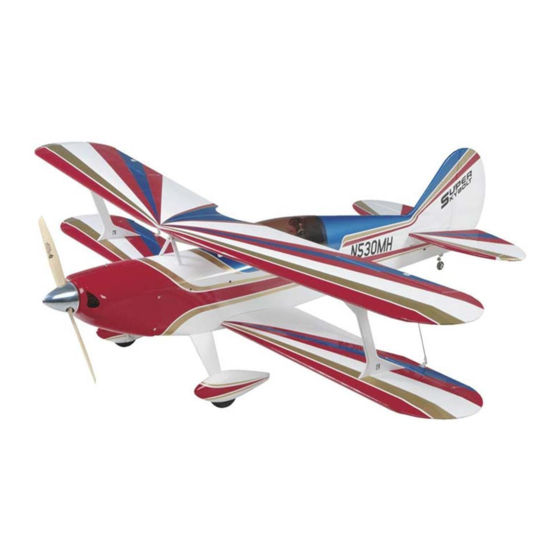
Wingspan: 57 in [1450 mm]
Wing Area: 924 sq in [59.6 dm
Weight: 7.5 – 8.5 lb [3400 – 3855 g]
Wing Loading: 19 – 21 oz/sq ft [57 – 65 g/dm
Length: 53 in [1345 mm]
Radio: 4-channel with four 54 oz-in [3.9kg-cm] servos
Engine: .60 – .75 cu in [10 – 12.5 cc] two-stroke,
.70 – .91 cu in [11.5 – 15 cc] four-stroke
Great Planes
®
Model Manufacturing Co. guarantees this kit to be free from defects in both material and workmanship at the date of purchase.
This warranty does not cover any component parts damaged by use or modification. In no case shall Great Planes' liability exceed the
original cost of the purchased kit. Further, Great Planes reserves the right to change or modify this warranty without notice.
In that Great Planes has no control over the final assembly or material used for final assembly, no liability shall be assumed nor accepted for
any damage resulting from the use by the user of the final user-assembled product. By the act of using the user-assembled product, the user
accepts all resulting liability.
If the buyer is not prepared to accept the liability associated with the use of this product, the buyer is advised to return this kit
immediately in new and unused condition to the place of purchase.
To make a warranty claim send the defective part or item to Hobby Services at the address below:
Include a letter stating your name, return shipping address, as much contact information as possible (daytime telephone number, fax number,
e-mail address), a detailed description of the problem and a photocopy of the purchase receipt. Upon receipt of the package the problem will
be evaluated as quickly as possible.
READ THROUGH THIS MANUAL BEFORE STARTING
CONSTRUCTION. IT CONTAINS IMPORTANT INSTRUCTIONS
AND WARNINGS CONCERNING THE ASSEMBLY AND
USE OF THIS MODEL.
© Copyright 2006
INSTRUCTION MANUAL
2
]
]
2
3002 N. Apollo Dr., Suite 1
WARRANTY
Hobby Services
Champaign, IL 61822
USA
Champaign, Illinois
(217) 398-8970, Ext 5
airsupport@greatplanes.com
GPMZ0188 for GPMA1242 V1.1
Advertisement
Table of Contents

Related Manuals for GREAT PLANES Super Skybolt


Summary of Contents for GREAT PLANES Super Skybolt
-
Page 1: Instruction Manual
Further, Great Planes reserves the right to change or modify this warranty without notice. In that Great Planes has no control over the final assembly or material used for final assembly, no liability shall be assumed nor accepted for any damage resulting from the use by the user of the final user-assembled product. -
Page 2: Table Of Contents
SCALE COMPETITION PREFLIGHT..............26 Identify Your Model ............26 Charge the Batteries ..........26 Though the Great Planes Super Skybolt is an ARF and may not Balance the Propellers ..........27 have the same level of detail as an “all-out” scratch-built Ground Check ............27 competition model, it is a scale model nonetheless and is Range Check.............27... -
Page 3: Safety Precautions
This is a partial list of items required to finish the Super Skybolt ARF that may require planning or decision making before 3. You must take time to build straight, true and strong. -
Page 4: Building Stand
Mixing sticks (50 – GPMR8055) ❏ Mixing cups (GPMR8056) ❏ The Super Skybolt ARF does not include a pilot figure. If you Builder’s Triangle Set (HCAR0480) ❏ plan to install one, the pilot can be attached during the build, 36" Metal ruler (HCAR0475) ❏... -
Page 5: Common Abbreviations
Replacement parts for the Great Planes Super Skybolt ARF • Whenever the term glue is written you should rely upon are available using the order numbers in the Replacement your experience to decide what type of glue to use. -
Page 6: Kit Inspection
If any parts are missing or are not of acceptable quality, or if you need assistance with assembly, contact Product Support. When reporting defective or missing parts, use the part names exactly as they are written in the Kit Contents list. Great Planes Product Support 3002 N. Apollo Drive, Suite 1 Champaign, IL 61822 Telephone: (217) 398-8970, ext. -
Page 7: Preparations
PREPARATIONS ❏ 1. If you have not done so already, remove the major parts of the kit from the box and inspect for damage. If any parts are damaged or missing, contact Product Support at the address or telephone number listed in the “Kit Inspection”... - Page 8 ❏ ❏ 7. Drill 1/16" [1.6 mm] holes for the servo mounting ❏ ❏ 4. Cut three arms from a four-arm servo horn and screws. Thread a mounting screw into each hole and back it install it onto the servo 90 degrees to the servo case. out.
- Page 9 ❏ ❏ 13. Connect the clevis to the third hole of the aileron control horn. Line the pushrod up with the servo horn while holding the aileron in the neutral position. Make a mark on the pushrod where it intersects the outer hole of the servo horn. ❏...
-
Page 10: Join The Wing Panels
Join the Wing Panels Use a bar sander with coarse sandpaper to true the edges and remove any excess hardened epoxy from the wing joiner prepared earlier. Without using any glue, temporarily join the wings with the joiner. Make adjustments as necessary for a good fit. -
Page 11: Build The Fuselage
❏ 8. When the epoxy in the previous step has cured, coat the ❏ 5. Set aside the bottom wing while the epoxy cures. other half of the aluminum joiner plate and top wing joiner with Locate the 3/16" x 13/16" [5 x 21 mm] anti-rotation pin and 30-minute epoxy. - Page 12 ❏ ❏ 3. Test fit the stabilizer in the fuselage. Center the stab left 6. Remove the stab from the fuse. Use a sharp #11 hobby and right in the fuselage. Stand back 15 to 20 ft [5 to 6 m] and knife or use the following Expert Tip to cut the covering check to be sure the stab is parallel to the wing.
-
Page 13: Install The Tail Linkages & Servos
❏ 8. Fit the vertical fin into the slot at the top trailing edge of the fuselage. As you did with the stabilizer, mark the location of ❏ 11. Attach the rudder to the vertical fin with CA hinges. the fuselage onto the fin. Remove the fin and trim away the covering 1/16"... - Page 14 ❏ 4. Cut three arms from two four-arm servo horns and enlarge the outer hole of each servo horn with a 1/16" [1.6 mm] drill bit. ❏ 8. Using the pushrods as a guide, place a large control horn onto the underside of each elevator and mark the positions of the mounting holes.
-
Page 15: Install The Landing Gear
❏ 11. Make a 90° bend at the mark and cut off the excess ❏ pushrod 1/4" [6 mm] beyond the bend. Hook the bend in the 14. Remove the wheel collar and cut off the right elevator pushrod to the outer hole of the servo horn and secure it with a pushrod at the mark you made. - Page 16 ❏ 3. Insert the tailwheel bushing into the hole in the fuselage. Slide the nylon retainer onto the tailwheel assembly guide wire. Insert the assembly into the tailwheel bushing and press the nylon retainer into the hole drilled in the rudder, leaving 5/16"...
-
Page 17: Install The Cabane Struts
❏ 2. Assemble the cabane struts as shown using four 4-40 2. The fuel system for the Super Skybolt ARF utilizes a x 3/8" [9.5 mm] Phillips screws and four 4-40 nylon lock nuts. three line system. There is a fill line, carb line, and vent Note that each cabane strut has a long and a short end. - Page 18 5-7/8" [149 mm] from the firewall. Use a secure the stopper using the Phillips head screw in the Great Planes Engine Hole Locator or a small drill bit to mark stopper assembly. Be careful not to overtighten the screw as the engine mounting holes onto the engine mounts.
-
Page 19: Install The Throttle Servo
❏ 12. Secure the engine to the mount with four 8-32 x 1" [25 mm] SHCS, four #8 flat washers, and four #8 lock washers. ❏ 2. Insert the white outer pushrod tube through the hole in the firewall and through the cutout in the former below the fuel tank retainer tab as shown. -
Page 20: Install The Receiver & Battery
Install the Receiver & Battery ❏ 5. Install the horn onto the throttle servo as shown. Start with an angle approximately 30 degrees from being perpendicular to the fuselage. This may need to be adjusted as you set up your radio system. ❏... -
Page 21: Finish The Model
❏ 5. Install your receiver battery switch onto the side of the fuselage. We used a Great Planes Switch & Charge Jack Mounting Set (GPMM1000). ❏ 3. Use a rotary tool to cut out the shape. Slide the cowl onto the fuselage. -
Page 22: Attach The Wings
[1.6 mm] holes 1/4" [6 mm] from the back edge of the cowl. Secure the cowl to the fuselage with four #2 x 1/2" [13 mm] SMS screws and four #2 washers. Be sure to use thin CA to harden the screw holes. ❏... - Page 23 underside trailing edge of the bottom wing. Continue the holes through the plate for the wing bolts using a 1/4" [6 mm] drill bit. ❏ 7. Using the same technique, attach the top wing to the wing struts. Bolt the top wing to the cabanes with two 4-40 x 1/2"...
-
Page 24: Optional: Assemble The Carrying Handle
1/4" [6 mm] beyond the bend. Hook the pushrods to the bottom aileron control horns and secure them with two For ease of transport, the Super Skybolt ARF includes a FasLinks. Adjust the clevises as necessary so the top and carrying handle that hooks to the top of the cabane struts. -
Page 25: Get The Model Ready To Fly
If, after you have become accustomed to the way the Super Skybolt ARF flies, you would like to change the throws to suit your taste, that is fine. However, too much control throw could make the model difficult to control, so remember, “more is not always better.”... -
Page 26: Balance The Model (C.g.)
added by using a “spinner weight” (GPMQ4645 for the 1 oz. Balance the Model (C.G.) [28 g] weight, or GPMQ4646 for the 2 oz. [57 g] weight). If spinner weight is not practical or is not enough, use Great Planes (GPMQ4485) “stick-on” lead. A good place to add More than any other factor, the C.G. -
Page 27: Balance The Propellers
We use a Top Flite Precision Magnetic Prop Balancer Keep your face and body as well as all spectators away from (TOPQ5700) in the workshop and keep a Great Planes the plane of rotation of the propeller as you start and run Fingertip Prop Balancer (GPMQ5000) in our flight box. -
Page 28: Ama Safety Code (Excerpts)
9) Under no circumstances may a pilot or other person touch AMA SAFETY CODE (excerpts) a powered model in flight; nor should any part of the model other than the landing gear, intentionally touch the ground, except while landing. Read and abide by the following excerpts from the Academy of Model Aeronautics Safety Code. -
Page 29: Flying
CAUTION (THIS APPLIES TO ALL R/C AIRPLANES): If, Take it easy with the Super Skybolt ARF for the first few while flying, you notice an alarming or unusual sound flights, gradually getting acquainted with it as you gain such as a low-pitched “buzz,”... - Page 30 OTHER ITEMS AVAILABLE (always ready on the right rudder to counteract torque) and FROM GREAT PLANES climb out to make another attempt. When you’re ready to make your landing flare and the model is a foot or so off the deck, smoothly increase up elevator until it gently touches down.
- Page 31 CA activator; Glue-B-Gone ™ adhesive remover; Pro Wood Glues; Pro Threadlocker; and Milled Fiberglass Reinforcer. GPMR6001 thru 6049 Great Planes C.G. Precision Aircraft Balancer ™ Accurate balancing makes trainers more stable, low-wings more agile, and pylon planes move at maximum speed. The...
-
Page 32: Engine Head Template
BUILDING NOTES Kit Purchased Date: _______________________ Date Construction Finished: _________________ Where Purchased:_________________________ Finished Weight: __________________________ Date Construction Started: __________________ Date of First Flight: ________________________ FLIGHT LOG ENGINE HEAD TEMPLATE...
Need help?
Do you have a question about the Super Skybolt and is the answer not in the manual?
Questions and answers