Table of Contents
Advertisement
Quick Links
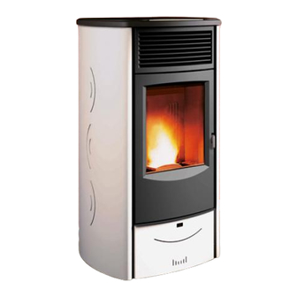
Pellet Stove
SABRINA
INSTRUCTIONS FOR INSTALLATION,
USE AND MAINTENANCE
Please read this entire manual before installation and use of this
pellet fuel-burning room heater. Failure to follow these instructions
could result in property damage, bodily injiury or even death.
Contact local building or fire officials about restrictions and
installation inspection requirements in your area.
Save these Instructions.
Advertisement
Table of Contents

Related Manuals for Piazzetta Sabrina


Summary of Contents for Piazzetta Sabrina
- Page 1 Pellet Stove SABRINA INSTRUCTIONS FOR INSTALLATION, USE AND MAINTENANCE Please read this entire manual before installation and use of this pellet fuel-burning room heater. Failure to follow these instructions could result in property damage, bodily injiury or even death. Contact local building or fire officials about restrictions and installation inspection requirements in your area.
-
Page 2: Important Information
In line with its policy of constant product improvement and renewal, the manufacturer may make changes without notice. This document is the property of Gruppo Piazzetta S.p.A.; no part of it may be disclosed to third parties without the written permission of Gruppo Piazzetta S.p.A. -
Page 3: Table Of Contents
CONTENTS DT2010187-00 Section Title Page GENERAL RULES Soot inspection Fresh air intake Outside combustion air Installation environment Capacity load of the floor Minimum safety distances Flueway Interior vent installation Connecting to a conventional chimney 1.10 Installing into an existing firebox chimney 1.11 Short rise installation –... -
Page 4: General Rules
1.0 GENERAL RULES DT2010216-05 Ensure that the installation of your product conforms to all the indications given below. Fig. 1 CHIMNEY STACK CHIMNEY CONNECTION TO FLUE FLUEWAY SOOT INSPECTION APERTURE FRESH AIR INTAKE ELECTRIC POWER SUPPLY CAPACITY LOAD OF THE FLOOR MINIMUM SAFETY DISTANCES DT2030321-01... -
Page 5: Fresh Air Intake
DT2010539-03 1.2 FRESh AIR INTAkE To ensure trouble-free operation the stove must have the necessary Fig. 2 air available for combustion and this is provided through the fresh air intake. The fresh air intake must: - have a total free cross section at least equal to the size given in the paragraph “TECHNICAL DATA”;... -
Page 6: Capacity Load Of The Floor
DT2010032-00 1.5 CAPACITy LOAd OF ThE FLOOR Check the load-bearing capacity of the floor, referring to the weight of the product given in the paragraph “TECHNICAL DATA”. If the floor does not have a suitable load-bearing capacity, adequate countermeasures must be taken. DT2011553-02 1.6 MINIMUM SAFETy dISTANCES Install the product in compliance with the recommended safety distances... -
Page 7: Flueway
DT2010229-05 1.7 FLUEwAy The stove requires a UL listed pellet vent. So the venting system shall be approved for pellet stoves by a certified testing Laboratory. PL Vent must be used for venting all Freestanding stoves. Do not use to vent pellet appliance these venting materials and products: - Dryer vent - Gas appliance (Type B) vent - PVC (plastic) pipe... - Page 8 Where 4” diameter pipe must be used, connect it to the stove flue outlet Fig. 8 with a 3” union-tee then use a 3” – 4” adaptor (Fig. 8). Ø 4" Ø 3" PELLET STOVE TEE W/TEE CAP DT2033009-00 Union-tee The use of this type of fitting must allow for the collection of condensate Fig.
-
Page 9: Interior Vent Installation
DT2010230-03 1.8 INTERIOR vENT INSTALLATION This kind of installation provides the natural draft that results from Fig. 10 a vertical rise avoiding smoke being released into the house when RAIN CAP electricity to the unit is interrupted while burning or smoldering pellets remains in the burn grate. -
Page 10: Connecting To A Conventional Chimney
DT2010232-02 1.9 CONNECTING TO A CONvENTIONAL ChIMNEy The stove may be connected to an existing Class A chimney or a masonry Fig. 12 chimney which meets the minimum requirements of NFPA 211. Using this kind of installation the pellet stove is able to draft naturally without exhaust blower operation (failure), reducing the probability of burn-back and back-drafting. -
Page 11: Installing Into An Existing Firebox Chimney
DT2010232-02 1.10 INSTALLING INTO AN ExISTING FIREbOx ChIMNEy This kind of installation also provides natural draft in the event of a Fig. 15 power failure. When installing as a hearth mount stove into a firebox the unit must either be relined, terminating above the chimney chase top, or positively connected to the existing chimney system using a block off plate (Fig. -
Page 12: Venting: Termination Requirements
This configuration will help prevent blockage of vent by snow drifts. Also the minimum vertical run of 5 feet (1.5 m) ensures the ventilation of the exhaust in the event of a power failure, and allow for easier cleaning through cleanout on tee. Certain local code restrictions may apply. -
Page 13: Prevention Of Domestic Fires
The clearance to a door, window or cavity must be at least: - 1.5’ (458 mm) below; - 1.5’ (458 mm) horizontally; - 9’’ (230 mm) above. The clearance to fresh air intake for combustion of the pellet stove or any other appliance, or the non-mechanical air supply inlet to the building must be at least 4’... -
Page 14: Mobile Home Installation
DT2010027-02 1.14 MObILE hOME INSTALLATION The stove has been tested and listed for mobile home installations. Unit must be installed in accordance with the: Manufactured Home and Safety Standard (HUD), CFR 3280, Part 24. In addition to all previously detailed requirements, mobile home installations must observe the following: - Permanently bolt the stove to the floor. -
Page 15: Technical Characteristics And Specifications
Ash drawer: ......removable Fuel: .........natural pure wood pellets (see section “FUEL”) Heating: ......forced ventilation Humidifier: ......stainless steel contains 6.8 oz (20 cl) water DT2012682-00 2.2 TEChNICAL dATA SABRINA Unit (at rated power) (at minimum power) Heat input BTU/H / (kW) 47081 / (13.79) -
Page 16: Product Identification Data
DT2011541-00 2.5 PROdUCT IdENTIFICATION dATA Every product is identified by a rating plate showing the model and the performance of the appliance as well as a plate giving the serial number. The rating plate is located on the rear panel of the stove, while the plate with the serial number is located on the underside of the hopper lid. A label bearing the serial number is also applied on the cover last page of the “Installation, operation and maintenance”... -
Page 17: Wiring Diagram
DT2034030-00 2.6 wIRING dIAGRAM Display of control WHITE Fuel feed Flue gas fan auger motor WHITE Room fan (blower) BLUE YELLOW GREEN Capacitor N.O. Hopper lid switch FUMI (normally open) BLUE SCAM. COC. ACC. WHITE Motherboard BLACK Serial port DB9 N.O. -
Page 18: Fuel
- inefficient combustion. recommend that you use high-quality pellets. Gruppo Piazzetta S.p.A has tested and programmed its stoves and Pellets should be stored in a sheltered, dry place. can ensure best performance and trouble-free operation using... -
Page 19: Installation
5.0 INSTALLATION DT2011597-00 Pursuant to current regulations on the safety of electrical equipment, Fig. 25 you must contact your dealer or a qualified electrician for all and any work connected with installation, maintenance or servicing that involves access to electrical parts. Cladding • Having completed assembly of the stove and installed any external room thermostat, check that the humidifier (optional) is properly... -
Page 20: Installing The External Thermostat
DT2011598-00 5.2 INSTALLING ThE ExTERNAL ThERMOSTAT The appliance is designed for connection to an external room thermostat Fig. 28 (not included in the package). To connect the thermostat use a 2x0.5 mm cable secured with a PG7 cable gland to be inserted in the relative hole in the rear panel (Fig. 30). Only authorised personnel should carry out this operation. -
Page 21: Side Flue Gas Outlet (Optional)
- Remove the side panel after unscrewing the 2 front screws [E] (Fig. Fig. 33 33) and loosen the rear screws [F] that secure it. (Fig. 34) DT2032466-00 - Follow the same procedure for the other side. Fig. 34 - Refit the cladding by repeating the above steps in the reverse order. DT2032467-00 DT2011599-00 5.4 SIdE FLUE GAS OUTLET (OPTIONAL) - Page 22 - Replace the removed pipe [D] with the side flue gas outlet connection Fig. 37 [E] to be found in the kit, inserting it fully into its seat and taking care to seal it with a gasket and a silicone-based (not cement-based) sealant.
-
Page 23: Use
A high torque motor that is capable of doing serious harm to fingers drives the auger and for this reason in Piazzetta pellet stoves a protective grille inside the hopper is placed. Don’t remove the protective grill inside the pellet hopper. -
Page 24: Control Panel
DT2011650-00 6.2 CONTROL PANEL - The stove is fitted with a digital control panel, which allows the user to control the various functions. - When the stove is connected to the electrical system but is not in the operating mode, the actual time (e.g.: 12:30) appears in the left part of the display, while the readout OFF appears in the right part. -
Page 25: Programming
DT2011652-00 6.4 PROGRAMMING Press key 6 for at least 5 seconds to enter stove programming. - Repeatedly press key 5 or 6 to scroll the main menu, which appears on the right-hand display. - Having selected the function to be programmed, confirm using the SET key. Now display the submenus by repeatedly pressing key 1 or 2 for the left-hand display and 5 or 6 for the right-hand display. -
Page 26: Setting Unit Of Temperature Measurement
DT2012660-00 6.5 SETTING UNIT OF TEMPERATURE MEASUREMENT This function allows the unit of temperature measurement in CELSIUS or in FAHRENHEIT to be set on the display. Description of activity Display Selecting the UNIT OF MEASUREMENT menu. Press the MENU button, use the MENU SELECTION button to select the UNIT OF UNIT OF MEASUREMENT MEASUREMENT menu and the SET button to confirm. - Page 27 This kind of timer allows you to have three programmes (DAILY, WEEKLY and WEEKEND) stored permanently. The programmes can be activated or deactivated using the SET CHRONO menu. It is advisable to have only one programme active at a time to avoid overlapping. WHEN USING THE TIMER FOR THE FIRST TIME, SET THE CLOCK WITH THE CURRENT DAY, HOUR AND MINUTES, as with a new watch.
- Page 28 Description of activity Display Use key 1 or 2 to scroll the options ON, to enable the weekly program, OFF, to disable. Confirm by pressing the SET key. ENABLED If you have disabled the program by selecting OFF and do not want to proceed with WEEK programming, press key 4 to exit.
-
Page 29: Energy Saving
Description of activity Display STOP It is possible not to set the stop time by setting the readout to OFF. Use key 1 or 2 to scroll the timetable band to find OFF, which appears at the end of the 24-hour cycle. WEEK END Confirm by pressing the SET key. -
Page 30: Parameters Menu
Description of activity Display Select the value to be set for ignition temperature. Press the SELECT MENU key and then select the temperature set point 2, 4 or 6 °F (1, START 2 or 3 °C) or disable the function by selecting OFF. Confirm by pressing the SET key. -
Page 31: Buzzer Enable
DT2011657-00 6.10 bUzzER ENAbLE This function is used to enable or disable the warning signal emitted if a safety device is activated. Description of activity Display Press key 6 for a few seconds. Use key 5 or 6 to scroll the menu that appears on the display until the scrolling readout BUZZER ENABLE appears. -
Page 32: Start Up And Normal Operation
DT2011659-00 6.13 START UP ANd NORMAL OPERATION • Before proceeding with lighting the stove: Operate unit only with hopper lid closed. Failure to do so may result in emmision of products of Ensure that the hearth door is well closed. combustion from the hopper under certain conditions. Never use gasoline, gasoline-type lantern fuel, kerosene, The mains plug is properly inserted into the socket. - Page 33 WAIT FOR START UP DT2040123-00 Description of activity Display The user attempts to restart the stove during the shutdown stage when the stove is still hot by pressing the ON/OFF key for a few moments. If the readout “WAIT FOR START UP” appears on the display by pressing the ON/OFF key for a few moments, it means that the stove is still hot and it is necessary to wait WAIT FOR START UP...
- Page 34 SHUTDOWN DT2011664-00 Description of activity Display Hold the ON/OFF key down for several seconds. Fuel loading stops, while the cooling fan and the extractor fan continue to operate until the stove is cool. The scrolling readout CLEANING GRATE first appears followed by the readout OFF. If the ENERGY SAVING MODE has been activated, the readout OFF is followed by ENS CLEANING GRATE to remember that energy saving mode is enabled.
-
Page 35: Remote Control (Optional)
DT2011646-00 6.14 REMOTE CONTROL (OPTIONAL) On request the stove may be supplied with a remote control, which can Fig. 44 be used to govern certain stove functions. - Startup/Shutdown: by pressing the two + keys simultaneously the stove can be turned on or off. - Power level: when operating normally, pressing the + and - keys above the flame symbol will select one of the four power levels of the stove. - Page 36 Description of activity Display Its function is to check correct operation of the pressure switch so that the stove can be used in all safety. It activates during the “START” stage of the stove (see “STARTING THE STOVE” table). SAFETY SMOKE If an anomaly is detected in the pressure switch, the readout “ALF 2”...
- Page 37 FLUE GAS TEMPERATURE SENSOR DT2040054-00 Description of activity Display Connected to the electronic board, it constantly monitors the working temperature allowing the stove to be used in all safety. If the temperature exceeds the fixed safety limit the board cuts off the power supply to the fuelloading auger thus depriving the grate of pellets and starting the stove shutdown process.
-
Page 38: Stove Status
DT2010248-04 6.16 STOvE STATUS This function displays the stove status under the various operating conditions. Description of activity Display Press key 6 for a few seconds. Use key 5 or 6 to scroll the menu that appears on the display until the scrolling readout STOVE STATUS STOVE STATUS appears. -
Page 39: Humidifier For Stove
DT2011671-00 6.18 hUMIdIFIER FOR STOvE The stove is provided with a niche for a humidifier (optional) located Fig. 46 under the ceramic insert of the top plate: once the ceramic cladding has been fitted, the humidifier can be filled with water. When refilling the humidifier do not exceed the maximum capacity, shown as max, otherwise the electrical parts of the stove could be damaged. -
Page 40: Maintenance
7.0 MAINTENANCE DT2011672-00 Pursuant to current regulations on the safety of electrical equipment, you must contact your dealer or a qualified electrician for all and any work connected with installation, maintenance or servicing that involves access to electrical parts or internal mechanical parts. Maintenance is to be considered compulsory for correct and efficient stove operation. -
Page 41: Cleaning The Firebox
DT2010428-03 7.3 CLEANING ThE FIREbOx Once a week clean the firebox as follows. Fig. 50 - Remove the grate baffle and draw out the grate. - Turn the eccentric clamps to free the internal baffle. - Lift the baffle slightly, gripping it by the two outer tabs to free it at the UPPER bottom and then turn it, bringing the bottom outwards, and remove. -
Page 42: Cleaning The Flue System
DT2010092-03 7.5 CLEANING ThE FLUE SySTEM Soot and Flyash: formation and need for removal. Fig. 54 The products of combustion will contain small particles of flyash. The flyash will collect in the exhaust venting system and restrict the flow of the flue gases. -
Page 43: Replacing The Window
The stove is fitted with a 0.197” / (5 mm) thick ceramic glass panel, resistant to thermal shock up to 1382°F / (750°C); the glass can only be broken by heavy impact or misuse. Do not slam the door or hit the window. In case of breakage replace only with a Gruppo Piazzetta spare part. To replace, proceed as follows: - wear protective gloves;... -
Page 44: Programming Maintenance
DT2012636-00 7.13 PROGRAMMING MAINTENANCE Scheduled maintenance must be carried out ONCE A YEAR and prior to starting up the appliance, especially after a long period of inactivity. This maintenance is necessary to ensure the appliance remains in efficient and safe working order. The appliance must be DISCONNECTED FROM THE POWER SUPPLY for all cleaning and maintenance work. -
Page 45: Troubleshooting
8.0 TROUbLEShOOTING DT2011179-01 Some of the problems indicated below may be resolved by following the instructions. All work must be carried out when the appliance is cold and disconnected from the electricity supply (pull out the plug). Authorised qualified persons must be contacted, in accordance with current regulations, whenever it is necessary to work on parts inside the cladding or the firebox in order to resolve the problem. - Page 46 Problem Cause Solution Pressure switch malfunction Replace the pressure switch (use only Faulty pressure switch “ALF 2” stove status original spares) Check the electrical connections No power supply to the auger (contact an authorised person) No connection between the 3-pin Flue gas speed malfunction terminal of the black-red-white cable Check correct insertion/position of the...
- Page 47 Problem Cause Solution “NO ACC” stove status Empty hopper Fill the hopper Grate requires cleaning Clean the grate (see section 7.1) Operating temperature not reached Empty the grate and restart Replace glow plug (use only original Faulty glow plug (igniter) spares) Replace the electronic board (use only Faulty electronic board...
-
Page 48: Replacing The Fuses
Problem Cause Solution Repeat ignition procedure. If the Appliance runs for 9-10 minutes and Heat sensor locked problem persists, contact an then goes out authorised technician Repeat ignition procedure. If the Combustion gases have not reached problem persists, contact an the required ignition temperature authorised technician Heat sensor badly connected... -
Page 49: Reference Standards
REFERENCE STANDARDS DT2010209-05 ASTM E1509 ..................Standard specification for room heaters, pellet fuel – burning type UL 1482.....................Room heaters, solid fuel type ULC S627 ..................Canadian standards needed for pellet fuel stoves UL 181....................Factory made air ducts and connectots UL 641....................Low-temperature venting system, type L ULC S609 ..................Low-temperature vents, type L Manufactured home and safety standard (HUD), cfr 3280, part 24 ..Mobile home installation NFPA (Fire) 211 ..................Standard for Chimneys, Fireboxes, Vents, and Solid Fuel-Burning Appliances... - Page 50 H07029330 / DT2001081 – 02...
- Page 52 PLEASE CONTACT YOUR DEALER FIRST. Distribuite by: Pacific Energy Fireplace Products Ltd. 2975 Allenby Rd. Duncan, BC, Canada V9L 6V8 Tel: 1-250-748-1184 email: support@pacificenergy.net Via Montello, 22 31011 Casella d’Asolo (TV) - ITALY Tel. +39.04235271 - Fax +39.042355178 www.piazzetta.it e-mail:infopiazzetta@piazzetta.it...
Need help?
Do you have a question about the Sabrina and is the answer not in the manual?
Questions and answers