Advertisement
Quick Links
Advertisement

Related Manuals for TeachLogic Maxim II


Summary of Contents for TeachLogic Maxim II
- Page 2 We appreciate your confidence by selecting a TeachLogic product and it is TeachLogic’s intent to support you in the use of your system. We hope you will take some time to review this manual to...
-
Page 3: How The System Works
The dome sensor detects that sequential signal and an electronic signal is sent to the receiver inside the Maxim II mixer/amplifier unit. The receiver decodes the signal from the sensor and converts it into an electronic audio signal that is sent to the amplifier. -
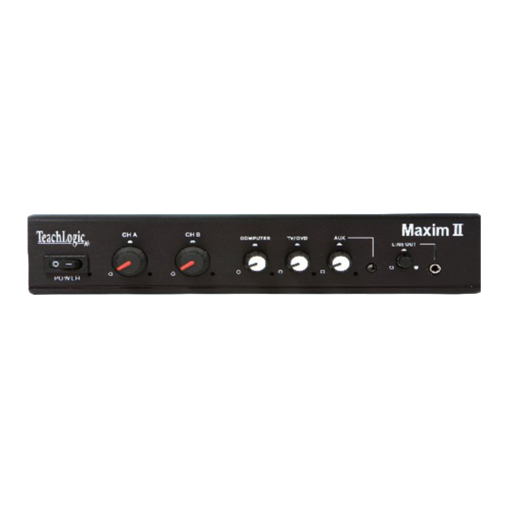
Page 4: Features And Description Of The Maxim System
Features and Description of the Maxim System Mixer/amplifier (IMA-420) nucleus classroom sound field system. The pendant transmitter, body- pack transmitter handheld microphone transmitter: transmit the vocal signal via infrared light to the dome sensor installed on the ceiling. The signal is then sent via cable to the receiver input of the mixer/amplifier. - Page 5 Rear Panel _________________________________________________ Power Input is 15 volts DC, 2.8 A. Two Amplifier Outputs each terminated by a dual latching Phoenix connector (facilitating connecting two speakers in parallel). Power output of each amplifier: 16 watt (RMS) into 4Ω load or 12 watt (RMS) into 8Ω...
- Page 6 The ceiling sensor is the preferred infrared sensor for optimum performance. It comes standard with Maxim II, Spectrum II, VoiceLink II and VoiceLink IV packages. This is the unit that needs to be installed on the ceiling. It comes with a mounting/support bracket and 50 feet of plenum rated cable with RCA connector on each end.
- Page 7 BRC-101 and BRC-202 drop-in chargers are for the handheld (IRH-30) and pendant transmitter (IRT-89). The single slot (BRC-101) can charge either or the dual (BRC-202) can charge both simultaneously. In addition, both have a tray to insert two “AA” batteries for recharging. Crescent (IRT-30) The Crescent is a lightweight microphone/transmitter designed...
- Page 8 Pendant Transmitter (IRT-89) with built-in microphone. pendant transmitter smallest transmitter and is usually worn around the neck. Two lanyards are provided: one with a safety breakaway clasp and a longer adjustable over the head style. The transmitting diodes are in portion rechargeable NiMH...
- Page 9 Plug-in Microphone (LM-300) is a small capsule size microphone that plugs directly into the top of the IRB-30 body-pack. A lanyard cord is provided to accommodate wearing the body-pack transmitter around the neck and utilizing it as a pendant microphone. A windscreen is included to prevent breath pops when used in close proximity to the mouth.
- Page 10 Handheld Microphone Transmitter (IRH-30) is most applicable student direct presentation. It has an “on/off” switch and a battery level indicator LED; Green=useable charge, Red=low battery. The transmitter has 10 emitting diodes around the bottom of the handle. The metal housing rovides low handling noise and insures durable longevity.
-
Page 11: Prior To Installation
• Wear proper work clothing and s turdy shoes • Clean all components with a dry cloth • Use Teachlogic accessori es only • Protect all cables from abrasion, sharp edges, and install in a tidy manner... - Page 12 • Where will the Maxim II (Rec eiver/Amplifier) be installed • How will the Maxim II be mounted • What will be the best routing of the speaker wires • Where are the Auxiliary Audio Sources located and how will they be Interfaced with the sound system •...
-
Page 13: Installation Procedure
Installing the Maxim II in an electronic equipment rack • Use the RM – 400 rack mount kit. • Mount the tabs on the side of the amplifier • Install the Maxim II in the rack at desired location... - Page 14 Installation of Speakers The Maxim II can accommodate four (8Ώ) speakers. You will connect two speakers in parallel and connect to one amplifier. Do the same for the other two speakers. This will distribute 8 watt to each sp eaker. Four speakers will be adequate to distribute sound evenly throughout a classroom of approximately 2500 sq.
- Page 15 • With the ceiling tile removed, measure the distance to the next speaker and cut a speaker cable appropriate length. • Strip the speaker cable ends approximately ¾” • String the cut speaker c able from speaker location to next speaker location. •...
- Page 16 Caution: Observe polarity, connect Red wire to (+) Red terminal and Black wire to Black (-) terminal. • Route the speaker cable to the Maxim II; observing safe, unsightly, least visible, and tidy route • Remove any soil, fingerprints and debris.
- Page 17 Insta llation of the Dome Sensor The preferred location for the dome sensor would be in the center (side to side) and favored forward towards the front. This will provide a clear and d irect IR transmission path from transmitter to sensor without any obstruction or interference.
- Page 18 nal Connection of the System ith all the two speaker wires and sensor cable neatly routed to the amplifier, we are ready to complete the installation. • Connecting the Dome Sensor • Plug the sensor cable into either of th e sensor input jacks (RCA) •...
- Page 19 Turn Maxim II “on”, powe r switch on left side • Red LED will light to indicate power • Set the Ch. A and Ch. B controls to 12 0’clock...
- Page 20 Ch. B. • Speak into the microphone and adjust the volume using Ch. B control on Maxim II. • While talking, walk a round the perimeter of the room to verify 100% reception of the signal.
- Page 21 Drop-in Battery Charger BRC-50 The BRC-50 charger is for recharging the batteries in the Body-Pack transmitter (IRB-30), Crescent transmitter (IR T-30) or Handheld trans mitter (IRH-30). Insert either transmitter into the fitted recep tacle. Charging will commence automatically. USE RECHARGEABLE NiMH BATTERIES ONLY he battery charger is a rather sophisticated charger.
- Page 22 BRC-101 and BRC-202 can recharge the batteries in the Pendant transmitter (IRT-89) or Handheld transmitter (IRH-30). Insert either ansmitter into the fitted stand receptacle. Charging will commence automatica lly. Two “AA” batteries can also be inserted into th e front ay for charging.
- Page 23 Useful Life Expectancy: 1½ - 2 years. • If you should observe: overheating of batteries or charger. Unplug charger immediately and either notify your dealer or TeachLogic. • Do not leave batteries in discharged state for e xtended periods of time.
- Page 24 • Turn “on” the Maxim II via the po wer switch • Plug a microphone into the body-pack and set the gain control at zero (max.
- Page 25 If LED is lit but there is no sound either condition cannot be resolved, call TeachLogic customer service. • When using the microphone, the voice is distorted and/or signal drop out occurs...
- Page 26 o If the noise and intermittent connection is associated with the movement of the cable, the cable connection needs to be repaired If your problem persists and this guide has not resolved the issue, call our customer service department for additional assistance.
- Page 27 General Specifications: Amplifier / Receiver (IMA-420) Receiver Input Infrared FM Modulation FM Wide-band Reception Frequencies Ch. A: 2.08 MHz Ch. B: 2.54 MHz Infrared 850 nm Wavelength Ch. A: 32.768 KHz Tone Signal 50 µs De-emphasis 40 Hz, -18KHz, ± 3dB Frequency Response ›65 dB S/N Ratio...
- Page 28 GENERAL TRANSMITTER SPECIFICATIONS Transmission Carrier Infrared Transmission Frequencies 2.08 MHz & 2.54 MHz Channel Switchable A or B Field Switchable Transmitting Diodes Modulation FM Wide-Band Pilot Tone Frequency 32.768 KHz Peak Deviation ± 25KHz Operating Range 2500 Ft². 60 Ft. Power Switch (Slide) On/Off Battery Charge Level (LED)
- Page 29 IRB–30 BODY-PACK TRANSMITTER Transmission Angle 180° User Controls User Controls Power Output Mic. Volume Power On/Off IR Power Output: (Hi/Lo) CH. Select (A or B) External Mic. Input Lo-z, 3.5mm Waist Band Clip Heavy Spring Wire Dimensions 4¾" H x 2¾" W x ¾" D Weight 4.8 oz.
- Page 30 BRC-50 DROP-IN BATTERY CHARGER Charging Slots Two Handheld, Slots A & C One Crescent, Slot B One Body-Pack, Slot D Charging Mode Switching Charging Current 1700ma ±10% Discharge Rate 350ma Red LED Indicator Batteries being Charged Green LED Indicator Batteries Fully Charged Yellow LED Indicator Batteries being Discharged Audible Alert...
- Page 31 SP-2000 2-WAY MALL-MOUNT SPEAKER Frequency Range 80 Hz to 16 kHz, ± 6dB Power 30 watts Continuous Sensitivity 88 dB SPL Impedance 8 Ω Crossover Frequency: 6 kHz Nominal Coverage 90° x 90° LF Driver (5.25 in) Polycarbonate / rubber High efficient 1”...
- Page 32 SP-628L 2-WAY LAY-IN CEILING SPEAKER Frequency Range 80 Hz to 15 kHz, ± 6dB Power 30 Watts Continuous Sensitivity 89dB SPL (1W/1M) Impedance 8Ω Crossover Frequency 6 kHz Nominal Coverage 90° x 90° LF Driver (5.25 in) Polymica / rubber Magnet 10 oz HF Driver...
-
Page 33: Five Year Limited Warranty
Five Year Limited Warranty TeachLogic Infrared products are guaranteed to be free of defects in workmanship or material for a period of five (5) years from date of original purchase, subject to the following conditions: 1. Warranty excludes defects caused by normal use and wear, any abuse, or failure to use the product in accordance per instructions.
Need help?
Do you have a question about the Maxim II and is the answer not in the manual?
Questions and answers