Table of Contents
Advertisement
Quick Links
Download this manual
See also:
Owner's Manual
Advertisement
Table of Contents

Subscribe to Our Youtube Channel
Related Manuals for TeachLogic MAXIM III


Summary of Contents for TeachLogic MAXIM III
- Page 1 MAXIM III INSTALLER AND OPERATIONS MANUAL ™ Amplifier Audio Mixer Infrared Microphone Receiver ® P/N UMM-500...
- Page 2 Congratulations on the purchase of your new Maxim III Sound Field system. You can be assured that the Maxim III fulfills all specifications and was produced to very high quality control standards. TeachLogic incorporates the latest state of the art technology, employs the most advanced manufacturing methodology and uses only premium quality components to assure many years of reliable performance.
- Page 3 Read Instructions All safety and operation instructions should be read before operating this TeachLogic product. Retain Instructions Safety and operating instructions should be kept for future reference. Water & Moisture certifications This product should not be operated near water.
- Page 4 Maxim III system info Date of Purchase: Model Number: Serial Number: Notes: 5-year limited warranty contact For full warranty details refer to: If you should encounter some unresolved issue, www.teachlogic.com/warranty please contact the TeachLogic customer service department for further assistance.
-
Page 5: Table Of Contents
table of contents System Overview ............ System Diagram ............Installation Installation Planning..........Installation of Ceiling Sensor ....... Installation of Speakers ......... Integration Page Mute/Pass Through Integration ....Fire Alarm Input ............RS-232 Feature ..........Security Alert Feature ..........Configuration Intial Setup ............... Trouble Shooting ............ -
Page 6: System Overview
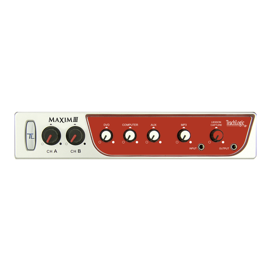
Sound Field system components 1. Speakers - ceiling or wall mount 2. Ceiling Sensor + 50' sensor cable (RCA) 3. Wireless Microphones (IRT-60 & IRH35) 4. Microphone battery charger (BRC-60 shown) 5. Maxim III Receiver/Amplifier... - Page 7 front of IMA-520 receiver/amplifier Aux Volume Control Power on/off MP3 Volume Control CH A Microphone Volume Control MP3 Input (3.5mm) CH B Microphone Volume Control Lesson Capture Volume Control DVD Volume Control Lesson Capture Output (3.5mm) Computer Volume Control 13 14 15 back of IMA-520 receiver/amplifier Speaker Output Security Alert - contact closure...
-
Page 8: System Diagram
Maxim III system diagram Ceiling/wall mount speakers owner’s man AGE MUTE PAGE PASS THROUGH TO owner’s man SPKR TERMINALS A1 &/OR A2 MAX 2 8Ω SPEAKERS /AMP IRE ALARM MIN 4Ω /AMP UTE INPUT POWER 25W/AMP @4Ω LEVEL 0.1 W... - Page 9 Ceiling sensor(s) nual nual ANTI-HUM Computer Personal music device Lesson capture recorder DVD Player ector or other imedia device...
-
Page 10: Installation
Maxim III installation installation planning Amplifer/Receiver: Choose location the based on accessibility requirements and wiring constraints for power, speakers, and audio devices. Ceiling Sensor: Centrally locate on ceiling; maintain line of sight; keep away from direct light and electrical interference. -
Page 11: Installation Of Ceiling Sensor
product description installation of ICS-55 ceiling sensor The ideal location for the ceiling sensor is in the center of the room's ceiling. The ideal installation is flush mounted on a white, reflective ceiling like the acoustic drop-down style. This will ensure 360º... -
Page 12: Installation Of Speakers
Maxim III installation installation of speakers The IMA-520 (and IMA-524) has two channels of amplified audio, rated for a minimum 4-ohm speaker load. There are two blue Phoenix style speaker connectors on the back panel, each providing two pairs of speaker terminals. The top connector provides connection to both channels as does the bottom connector. - Page 13 SP-628 ceiling speakers SP-2000 wall mount speakers 1. Determine the listening area. 1. Determine the mounting surface and 2. Divide listening area into quadrants location based on the seating area 3. Locate and identify the center most tile 2. Ordinary installation is to locate the in each quadrant speakers on each side wall.
-
Page 14: Integration
When a signal of adequate level (voltage) is sensed on the page mute input terminal, all other audio inputs to the Maxim III are muted to allow the building-wide page to be heard. The muting is applied to wireless microphones as well as computer, DVD, and all other line inputs. -
Page 15: Fire Alarm Input
(before mute). In the event of a loss of AC power, the TeachLogic amplifier will continue to pass the page on to 2 of the speaker connections as outlined on the following diagram. -
Page 16: Rs-232 Feature
This allows the receiver/amplifier to be placed in an area or compartment that is not easily accesssed by the user. Codes that are required for this setup are also available below or from the TeachLogic website. blank page RS-232 codes... -
Page 17: Security Alert Feature
Note: the wireless channel B does not trigger security alert. The Maxim III may be set to provide either 4- or 1-pulse signal at the relay. This new feature allows the user to change from 1 to 4 pulses, or 4 to 1 pulse. Different monitoring systems may require one or the other. - Page 18 Move the RS-232 switch from ON to OFF and back again FIVE times. Then release the front panel power button. Using the previous process, check the mode to confirm that the Maxim III is in the desired 1-pulse or 4-pulse mode. If not, repeat the steps above to change the mode.
- Page 19 Power button RS-232 switch security alert activation test Ensure the amplifier is powered on and a solid blue light appears on the power button. Ensure the ceiling sensor is attached to the amplifier. The sensor's green LED should be illuminated. Power on the IRT-60 Sapphire microphone that uses Ch.
-
Page 20: Configuration
AMPLIFIER • Turn the Maxim III on by pushing the power button. A solid blue LED indicates amplifier is powered ON. • Confirm there's power to the ceiling sensor: A green LED on edge of sensor should be illuminated •... -
Page 21: Troubleshooting
• Verify there is no obstruction between transmitter and sensor • Ensure there is no direct sunlight on sensor contact If your problem persists and this guide has not resolved the issue, contact our customer service department for additional assistance. (760) 631-7800 support@teachlogic.com... -
Page 22: System Specifications
Maxim III Specifications transmitter Maxim III (IMA-520) specs. Receiver Input Infrared FM Modulation FM Wide-band Reception Frequencies Ch. A: 2.08 MHz | Ch. B: 2.54 MHz Infrared Wavelength 850 nm Pilot Signal 32.768 KHz De-emphasis 50 µs Frequency Response 50 Hz - 13KHz, ± 3dB S/N Ratio ›65 dB... - Page 23 Sapphire transmitter (IRT-60) specs. Transmitting Diodes Operating Range 60 Ft. Line of Sight Battery Discharge Indicator Blue Full Purple Medium Flashing Red Very Low Battery Battery Used Lithium-ion (3.7V / 620mAh) Battery Life Approx. 8-9 Hrs/Charge External Power Charger DC +5V, Micro USB Connector Transmission Angle Conical User Controls...
- Page 24 7800 • • • support@teachlogic.com P/N UMM-500 teachlogic.com rev003 20190513...
Need help?
Do you have a question about the MAXIM III and is the answer not in the manual?
Questions and answers