TeachLogic Maxim III Installation Manual
Classroom audio system amplifier / mixer / receiver
Hide thumbs
Also See for Maxim III:
- Owner's manual (28 pages) ,
- Installation and operation manual (24 pages)

Related Manuals for TeachLogic Maxim III


Summary of Contents for TeachLogic Maxim III
- Page 1 Maxim ™ Classroom Audio System Amplifier | Mixer | Receiver Installation Manual...
- Page 2 Sound Field system. You can be assured that the Maxim™ III fulfills all specifications and was produced to high quality control standards. TeachLogic incorporates the latest state of the art technology, employs the most advanced manufacturing methodology and uses only premium quality components to assure many years of reliable performance.
- Page 3 Safety Instructions Read Instructions Power Cord Caution All safety and operation instructions should be Power cable should be routed clear of read before operating this TeachLogic product. foot traffic and supported clear of kinking or abrasion. Retain Instructions Object Protection Safety and operating instructions should be kept for future reference.
- Page 4 Date of Purchase Model Number Serial Number Notes Contact If you should encounter an unresolved issue, please contact the TeachLogic customer service department for further assistance. 760-631-7800 | support@teachtogic.com | teachlogic.com Limited warranty For full warranty details refer to teachlogic.com/warranty.
-
Page 5: Table Of Contents
Table of Contents Maxim ™ Contents System Overview ........................5 System Diagram ......................... 6 Installation ..........................7 Installation Planning ........................7 Installation of Ceiling Sensor ....................... 8 Installation of Speakers ....................... 9 Integration ..........................10 Page Mute/Pass Through Integration ................... 10-11 Fire Alarm Input ........................ -
Page 6: System Overview
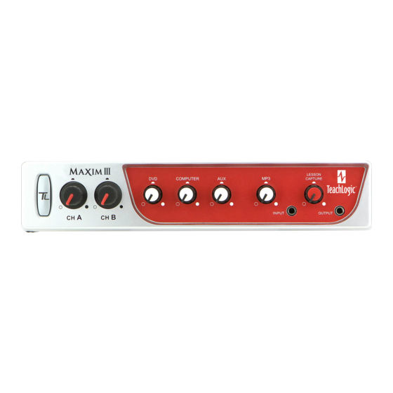
Maxim System Overview ™ Front of IMA-520 receiver/amplifier Power Button/ “TL” Indicator LED Computer Input Volume Control Channel A Microphone Volume Control Aux Input Volume Control Channel B Connectivity Indicator LED MP3 Volume Control Channel B Microphone Volume Control MP3 Input Port (3.5 mm) Channel B Connectivity Indicator LED Lesson Capture Volume Control DVD Volume Control... -
Page 7: System Diagram
Maxim Installation ™... -
Page 8: Installation
Maxim Installation ™ Installation planning Amplifier/Receiver: Choose location that supports accessibility requirements and wiring constraints for power, speakers, ceiling sensor, and audio devices connecting to the amplifier. Ceiling Sensor: Locate in the center of the ceiling; maintain line of sight; keep away from direct light and electrical interference. -
Page 9: Installation Of Ceiling Sensor
Maxim Installation ™ Installation of Ceiling Sensor (ICS-55) The ideal mounting location is in the center of the room's ceiling. The ideal installation is flush mounted on a white, reflective ceiling like the acoustic drop-down style. This will ensure 360º coverage and will minimize the transmission distance for more reliable performance. -
Page 10: Installation Of Speakers
Maxim Installation ™ Connection of speakers The IMA-520 has two channels of amplified audio, rated for a minimum 4-ohm speaker load (two 8-ohm speakers each). There are two blue phoenix style speaker connectors on the back panel, each providing two pairs of speaker terminals. The top connector provides connection to both channels as does the bottom connector. -
Page 11: Integration
Page Mute/Page Pass Through Maxim ™ Page Mute/Page Pass Through System behavior for Page Mute When a signal of adequate level (voltage) is sensed on the page mute input terminal, all other audio inputs to the Maxim™ III are muted to allow the building-wide page to be heard. The muting is applied to wireless microphones as well as computer, DVD, and all other line inputs. - Page 12 (before mute). In the event of a loss of AC power, the TeachLogic amplifier will continue to pass the page on to two of the speaker connections as outlined on the following Diagram A. Only the upper left and lower right speaker outputs will pass page without power.
-
Page 13: Fire Alarm Input
This feature requires a contact closure from the Fire Alarm Panel and the TeachLogic terminal is for a normally open connection. When there is continuity between the terminals (closed condition) muting will occur and will continue for 10-15 seconds after contacts are open. -
Page 14: Rs-232 Feature
This allows the receiver/amplifier to be placed in an area or compartment that is not easily accessed by the user. Codes that are required for this setup are available on the teachlogic/com/resources page under “Application Notes” or directly at https://TeachLogic.com/TeachLogic-app-notes-rs- 232-control/. -
Page 15: Security Alert Feature
Security Alert Interface Maxim ™ Security Alert Feature Effective for shipments after this date of new or reprogrammed units. Serial numbers beginning with A19 and later (letter or number is A, B, C… and number is 19, 20, …).The Maxim™ III security alert feature, when triggered by an IRT-60 sapphire mic on Channel A, creates a relay contact closure or opening. - Page 16 Security Alert Interface Maxim ™ To change the mode: Whether mode is 1-pulse or 4-pulse, the steps below will change it to the other mode. If power state is ON (Blue LED at power button), press once to set power state OFF (Red LED). If Red, then you may start the mode switching process.
-
Page 17: Configuration
• If using two IRT-60 microphones in the same room, one must be changed to channel B to avoid interference. Watch the how-to video on teachlogic.com/resources. Note: Next steps are best performed with a second person as the listener •... -
Page 18: Troubleshooting
If sensor is mounted on a dark surface or without a flush ceiling surface, reception can be hampered. Contact If your problem persists and this guide has not resolved the issue, contact our customer service department for additional assistance. (760) 631-7800 | support@TeachLogic.com... -
Page 19: System Specifications
Maxim Specifications ™ Maxim™ III (IMA-520) specs Receiver Input Infrared FM, 2 wireless mic channels Modulation Wide-band FM Reception Frequencies Ch. A: 2.08 MHz | Ch. B: 2.54 MHz Deviation 10 kHz Nominal, 25 kHz Maximum De-emphasis 50 µs Tone Signal 32.768 kHz Infrared Wavelength 850 nm... - Page 20 Maxim Specifications ™ Sapphire (IRT-60) microphone/transmitter specs Transmission Carrier Infrared Transmission Frequencies 2.08 MHz & 2.54 MHz Channel Selection Field Switchable Transmitting Diodes Wavelength 850 nm Modulation FM Wide-Band Frequency Response 100 Hz - 10 KHz Pilotone Frequency 32.768 KHz Peak Deviation ±...
- Page 21 541 E. Main St. Longmont, CO 80501 teachlogic.com | support@teachlogic.com | 760-631-7800 P/N UMM-500 20200903...
Need help?
Do you have a question about the Maxim III and is the answer not in the manual?
Questions and answers