Table of Contents
Advertisement
Advertisement
Table of Contents

Related Manuals for TeachLogic Maxim II


Summary of Contents for TeachLogic Maxim II
-
Page 2: Table Of Contents
TABLE OF CONTENTS Foreword ……………………………………………..…………. i How the System Works ………………………………….……... ii Features and Description of the Maxim System ……………….. 1 Front Panel ……………………………………………….. 1 Rear Panel ………………………………………………… 2 Infrared Dome Sensor (ICS-50) ………………………….……… 3 Drop-in Battery Charger ………………………………………… 3 BRC-30 ……………………………………………………. - Page 3 We hope you will take some time to review this manual to familiarize yourself with the product features and its performance. The manual will help guide you to gain maximum use and benefit of the Maxim II sound field system.
-
Page 4: How The System Works
The dome sensor detects that sequential signal and an electronic signal is sent to the receiver inside the Maxim II mixer/amplifier unit. The receiver decodes the signal from the sensor and converts it into an electronic audio signal that is sent to the amplifier. -
Page 5: Features And Description Of The Maxim System
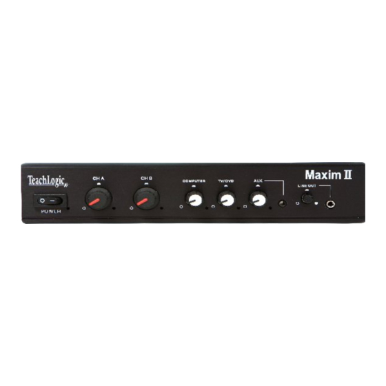
Features and Description of the Maxim II System Mixer/amplifier (IMA-420) is the nucleus of the classroom sound field system. The pendant transmitter, body-pack transmitter or handheld microphone transmitter: transmit the vocal signal via infrared light to the dome sensor installed on the ceiling. The signal is then sent via cable to the receiver input of the mixer/amplifier. -
Page 6: Rear Panel
Rear Panel _________________________________________________ Power Input is 15 volts DC, 2.8 A. Two Amplifier Outputs each terminated by a dual latching Phoenix connector (facilitating connecting two speakers in parallel). Power output of each amplifier: 16 watt (RMS) into 4 load or 12 watt (RMS) into 8... -
Page 7: Infrared Dome Sensor (Ics-50)
Infrared Dome Sensor (ICS-50 ) is installed on the ceiling. It is the component that collects the infrared transmission signal via 30 detecting diodes. sensor sends information mixer/amplifier and via a shielded cable. Drop-in Battery Chargers The battery chargers were specifically designed to recharge NiMH batteries at an optimum rate to maximize their usage. -
Page 8: Pendant Transmitter (Irt-89)
Pendant Transmitter (IRT-89) with a built-in microphone. The pendant transmitter is the smallest transmitter and is usually worn around the neck. Two lanyards are provided: one with a safety breakaway clasp and a longer adjustable over head style. transmitting diodes are in the top portion and the rechargeable NiMH batteries are housed below. -
Page 9: Plug-In Microphone (Lm-300)
Plug-in Microphone (LM-300) is a small capsule size microphone that plugs directly into the top of the IRB-30 body-pack. A lanyard cord is provided to accommodate wearing the body-pack transmitter around the neck and utilizing it as a pendant microphone. A windscreen is included to prevent breath pops when used in close proximity to the mouth. -
Page 10: Speakers
Handheld Microphone Transmitter (IRH-30) is most applicable for student use or direct presentation. It has an “on/off” switch and a battery level indicator LED; Green=useable charge, Red=low battery. The transmitter has 10 emitting diodes around the bottom of the handle. The metal housing provides low handling noise and insures durable longevity. -
Page 11: Wallmount Speaker (Sp-2000)
Do not install your system near water or heat sources Wear proper work clothing and sturdy shoes Clean all components with a dry cloth Use Teachlogic accessories only Protect all cables from abrasion, sharp edges, and install in a tidy manner The following Tools/Supplies required for Installation ... -
Page 12: Installation Procedure
Maxim Installation Procedure Installation of the Maxim II Placement of the Maxim II mixer/amplifier is usually dictated by: what other equipment will be integrated with the sound system, and how it will be mounted. Location of the electrical AC power outlet and the routing of the speaker and sensor cables. -
Page 13: Installation Of Speakers
Use the RM – 400 rack mount kit. Mount the tabs on the side of the amplifier Install the Maxim II in the rack at desired location Installation of Speakers The Maxim II can accommodate four (8Ώ) speakers. You will connect two speakers in parallel and connect to one amplifier. - Page 14 Trace and cut the speaker hole using a keyhole or drywall With the ceiling tile removed, measure the distance to the next speaker and cut a speaker cable appropriate length. Strip the speaker cable ends approximately ¾” ...
-
Page 15: Installation Of Dome Sensor
Caution: Observe polarity, connect Red wire to (+) Red terminal and Black wire to Black (-) terminal. Route the speaker cable to the Maxim II; observing safe, unsightly, least visible, and tidy route Remove any soil, fingerprints and debris. -
Page 16: Final Connection Of System
Route the sensor cable either up through the ceiling if feasible or surface mount using a raceway or use of self adhesive wire tie pads & wire ties Route to the Maxim II amplifier If surface mounting, observe straight taut runs in a tidy manner ... -
Page 17: Operating The System
Turn Maxim II “on”, power switch on left side Red LED will light to indicate power Set the Ch. A and Ch. B controls to 12 0’clock... -
Page 18: Brc-30
Ch. B. Speak into the microphone and adjust the volume using Ch. B control on Maxim II. While talking, walk around the perimeter of the room to verify 100% reception of the signal. -
Page 19: Brc-101 And Brc-202
Place handheld microphone and/or body-pack transmitter into their appropriate slot A Red LED will light indicating unit is charging At full charge, the LED will change to Green. An audible buzzer will buzz an alert when the batteries are fully charged. - Page 20 Otherwise, it is an indication the batteries have reached their service life and need to be replaced. Useful Life Expectancy: 1½ - 2 years. If you should observe: overheating of batteries or charger. Unplug charger immediately and either notify your dealer or TeachLogic.
- Page 21 Congratulations, this completes the installation and it is now time to show the user how to use the system Turn “on” the Maxim II via the power switch Plug a microphone into the body-pack and set the gain control at zero (max.
-
Page 22: Trouble Shooting
If LED is lit but there is no sound If either condition cannot be resolved, call TeachLogic customer service. When using the microphone, the voice is distorted and/or signal drop out occurs o Check the charge on your batteries ... - Page 23 recharge to full charge. (Time required 4 -6 hours) Recheck the system after cycling the batteries If the problem persists, replace the batteries When using the body-pack transmitter and microphone, the voice is intermittent and/or has a static like sound o Try moving the cable back and forth at the plug-in connector where...
-
Page 24: Specifications
General Specifications: Amplifier / Receiver (IMA-420) Amplifier and Mixer: Two Power Amplifier: 12 watt ea. into 8 load 16 watt ea. into 4 load 32 watt max (RMS)l 40Hz – 18KHz, 3 dB Frequency Response S/N Ratio >65dB < 1%@1KHz (3) Aux Inputs Line Level w/+ 15dB gain Front Panel Input... - Page 25 Current Consumption Hi - 400ma Lo - 330 ma Range Hi about 30 yds. Lo about 20 yds Microphone Input 3.5mm jack, Lo-z Battery Two Rechargeable NiMH, 1.2v / 2650mAH Battery Life Approximately 7 Hours Dimensions 4⅜” H x 2⅝” W x ¾” D Weight 4.8 oz.
- Page 26 Charging Time 1.5 - 3Hr. Power Supply 12VDC / 1.5A (Fuse protected) Dimensions 6½” L x 3⅜” W x 1½” H Weight 12.2 oz. ICS - 50 CEILING DOME SENSOR Operating Frequency 2MHz to 2.6 MHZ Number of IR LED’s 30 Radial Spaced Interconnection 50Ft.
Need help?
Do you have a question about the Maxim II and is the answer not in the manual?
Questions and answers