Table of Contents
Advertisement
Advertisement
Table of Contents

Subscribe to Our Youtube Channel
Related Manuals for Wincor Nixdorf BA82


Summary of Contents for Wincor Nixdorf BA82
- Page 1 BA82 LCD TFT 12.1" (30.7 cm) Flat Panel Display User Guide...
- Page 2 Please send us a copy of this page if you have any constructive criticism. We would like to thank you in advance for your comments. With kind regards. Your opinion: Wincor Nixdorf International GmbH Dokumentation RD HWD01 Rohrdamm 7 Haus 16 D-13629 Berlin E-Mail: retail.documentation@wincor-nixdorf.com...
- Page 3 BA82 Flat Panel Display User Guide Edition August 2010...
- Page 4 All brand and pro duct na mes men tio ned in this do cu ment are tra de marks of their re spec ti ve owners. Co py right© Win cor Nix dorf In ter na tio nal GmbH, 2010 The re pro duc ti on, trans mis si on or use of this do cu ment or its con tents is not per mit ted wit hout ex press aut ho ri ty.
-
Page 5: Table Of Contents
About this Ma nu al ......2 The Flat Pa nel Dis play BA82 ....3 Ge ne ral . - Page 6 Con nec ti on Be zel ......21 Con nec ting the BA82 ......21 Moun ting Po si tions.
- Page 7 Mo dus ........58 Crea ting Tab les ......58 Soft wa re In ter fa ces .
-
Page 8: Introduction
The low-ener gy, fli cker free and ra di ati on-free co lour mo ni tor of the BA82 is an LCD in TFT-tech no lo gy (Thin Film Tran sis tor). -
Page 9: About This Manual
(soft wa re and hard wa re), the ope ra ti on and the main ten an ce of your BA82. Some parts of this book re qui re fa mi lia ri ty and ex per ien ce in wor king with ope ra ting sys tems and in stal la ti on and con fi gu ra ti on procedures. -
Page 10: The Flat Panel Display Ba82
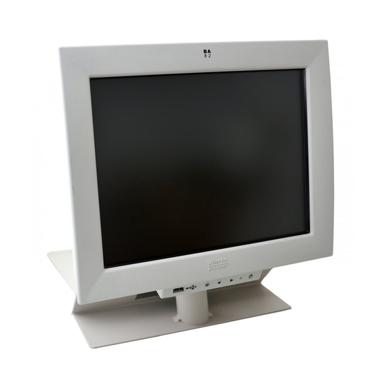
FLAT PANEL DISPLAY BA82 The Flat Panel Display BA82 General The TFT LCD flat panel display is an SVGA-com pa ti ble 12.1-inch flat panel display which is ab so lu te ly fli cker free and free from ra di ati on. It is de sig ned for a re so lu ti on of max. -
Page 11: Usb Inter Fa Ce
With this key you can switch the system into ‘Wake up Mode’ or ‘Sleep Mode’ provided a Remote function (see page 18) for the BA82 is availabe (i.e. the cable is connected to a BEETLE system via a remote connector). -
Page 12: Se Cu Ri Ty
FLAT PANEL DISPLAY BA82 Se cu ri ty The operator panel module can be mounted horizontally turned thus to handicap the access. Slightly press the module inwards at the left and right hand side (1). Remove the module of the recesses and carefully move it off downwards (2). -
Page 13: Integrated Loudspeakers
FLAT PANEL DISPLAY BA82 Integrated Loudspeakers The two integrated loudspeakers are located at the bottom side of the screen (see arrows). -
Page 14: Capacitive Touch Screen
Connecting a BA82 for the first time we approve to calibrate the Touch Screen. Details depend on the Operating System that you use. -
Page 15: Clea Ning In Struc Tions
CAPACITIVE TOUCH SCREEN Clea ning In struc tions Al ways turn off the sys tem be fo re clea ning. The glass sur fa ce of your Touch Screen should be clea ned with a mild, abrasive free, com mer ci al ly avai la ble glass clea ning pro duct. All pH neut ral ma ter ials (pH 6 to 8) are good for clea ning. -
Page 16: Infrarot Touch Screen
INFRAROT TOUCH SCREEN Infrarot Touch Screen Ge ne ral The infrared (IR) technology is based on the interruption of a grid of IR light beams before the surface of a screen. The touch frame contains a row of infrared light emitting diodes (LEDs) and photo transistors, each mounted on two opposite sides to create a grid of invisible infrared light. -
Page 17: Clea Ning In Struc Tions
INFRAROT TOUCH SCREEN Breaking through the grid has the same ef fect as cli cking the left mou se but ton. Therefore, touching the glass is not necessary. To avoid malfunctions: Do not fix labels or stickers on the frame and do not put pencils or the like on the inner frame. -
Page 18: Swipe Card Reader (Optional)
SWIPE CARD READER (OPTIONAL) Swipe Card Reader (optional) The swi pe card rea der (MSR Mo du le), that is avai la ble as an op ti on, can read three ISO tracks si mul ta ne ous ly in a sing le swi pe. -
Page 19: Keyboard (Optio N)
KEYBOARD (OPTIO N) Keyboard (Optio n) The keyboard is connected directly to the display via a USB interface. It is fitted to the right-hand side of the screen. The keyboard is available with or without a swipe card reader. Clea ning In struc tions The key bo ard should be clea ned with a ger mi ci de from time to time. -
Page 20: Ex Chan Ging The Keys
KEYBOARD Ex chan ging the Keys You can re mo ve each of the key caps using the key re mo val de vi ce en clo sed, pul ling the key up wards. Pla ce the key re mo val de vi ce on the se lec ted key un til you hear a click. -
Page 21: In Ser Ting Key La Bels
KEYBOARD In ser ting Key La bels Be low, you will find in struc tions on how to in sert the key la bels: Each key should be la bel led in di vi du al ly. You can use the emp ty la bels de li ver ed with the sys tem to do so. -
Page 22: Swipe Card Reader In A Keyboard (Optional)
SWIPE CARD READER IN A KEYBOARD (OPTIONAL) When in ser ting dou ble ac tua ting cy lin der keys, plea se en su re that the actuating cy lin der is on the left (horizontally inserted key) resp. on top (vertically insertion). -
Page 23: Installing And Securing
Wincor Nixdorf sales outlet. Trans port the de vi ce only in its ori gi nal pa cka ging (to pro tect it against im pact and shock). - Page 24 INSTALLING THE BASE Loosen the four screws on the screen for approx. 2 mm. Put the screen element on to the base. P-USB DVI-I Wincor Nixdorf BA8X/ cTouch 5V/ 12V 017500 000000 0.7A/ 0.7A I.T.E. IC 78+E146247 0199900107 Made in China...
-
Page 25: Table Mounting
TABLE MOUNTING Table Mounting Underneath the cable cover there are two holes in the BA82 stand (see large arrows) with a diameter of 5.5 mm. The holes can be used to fix the stand on the footprint with appropriated screws. We recommend using screws with a diameter of 4.0 to 5.0 mm. -
Page 26: Mounting The Tube Adapter
For the mounting you need a Phillips head screwdriver for fixing and releasing the screws. Pull the co ver downwards. Loo sen four screws at the rear side of the BA82 and put them asi - Mount the tube adap ter on the rear side of the BA82... - Page 27 MOUNTING THE TUBE ADAPTER Af ter cab ling the dis play put on the co ver pro vi ded. Put the dis play with the adap ter on the preins tal led tube (1) and fix it with the screw (2).
-
Page 28: Connection Bezel
Only UL Listed LPS (Limited Power Source) power supplies can be used. By connecting the system's cable the screen will be switched on. Connecting the BA82 Remove the bezel of the monitor and the cable cover of the base. Before connecting cables switch off the system and disconnect it from the... - Page 29 CONNECTION BEZEL When laying this cable please mind to slightly clamp it (with a loop) into the strain relief. Lay the cable into the guidance inside the base. Lay a USB-A cable loosely-fitting into the strain relief. When passing the cables please mind the following maximal cable diameters (in mm).
-
Page 30: Mounting Positions
MOUNTING PERIPHERALS Mounting Positions There are three mounting positions .Two (at the left and right hand side) can be used to install Magnetic Card Reader; a keyboard may be installed at the right hand side. The third position is located above the screen. Other units (e.g. -
Page 31: Ergonomic Terminal Workplace
ERGONOMIC TERMINAL WORKPLACE Ergonomic Terminal Workplace Plea se ob ser ve the fol lo wing when set ting up your ter mi nal work pla ce: Avoid di rect gla ring and re flec ti ve gla ring. Use the screen only in a con trol led lu mi nan ce su roun ding. -
Page 32: Mounting Peripherals
Keyboard and Swipe Card Reader The delivery contains the keyboard with Swipe Card Reader, the connected cable, the pre-installed holder (BA83), the holder (BA82), two screws and a set of keys including a key remover. Do not release the loop! Turn the keyboard and push the cover aside (see... - Page 33 MOUNTING PERIPHERALS Loosen the two screws (see arrows), remove the bracket (BA83) and lay it aside. Turn the screen around and remove the bezel (see page 16). Loosen the screws beneath the cover. Lift the screen out of the holder to the top. Lay the screen on an appropiate base.
- Page 34 MOUNTING PERIPHERALS Loosen the snap arms of the loudspeaker's bezel (see arrows). Flap the bezel downwards. Carefully press out the blind screen from inside.
- Page 35 MOUNTING PERIPHERALS Push the bracket (BA82) into the opening of the housing, so that high buckled strapes are fitting in the slits. Tilt down the bracket. Take care that the upper parts of the hooks (see arrows) are above the plate! The screws match with the keyholes.
- Page 36 MOUNTING PERIPHERALS You must always discharge yourself (e. g. by touching a grounded object) before mounting. Take care to pull the connector off the keyboard. Pass the keyboard cable through the housing of display into the cable guidance and connect it (see arrow).
- Page 37 Screw Tighten the keyboard, tauten and run the cable. If you are going to use the USB interface at the backside of the BA82 then run the cable through the strain relief as shown below. Put the cable loop into the housing.
- Page 38 MOUNTING PERIPHERALS If devices have a second Hub, you can connect the keyboard at the next free interface. To do so, release the cable's loop and run the cable through the strain relief. Strain relief USB interfaces (HUB) Insert the cover of the keyboard as shown below. The bar is corresponding to the gap (1) and push it to the housing until it is engaged (2).
-
Page 39: Magnetic Swipe Card Reader
The delivery contains the Swipe Card Reader, the connected cable, a pre-installed holder (BA83); a holder (BA82) and two screws. Do not release the cable loop. Turn the Swipe Card Reader and push the cover sidewards (see arrow). -
Page 40: Moun Ting On The Right Side
MOUNTING PERIPHERALS Moun ting on the right Side Loosen the Phillips screws and remove the bracket (BA83) and put it aside. Turn the screen and remove the cover (see page 16). Loosen and remove the screws beneath the cover. Lift the screen out of the holder to the top. Lay the screen on an appropiate base. - Page 41 MOUNTING PERIPHERALS Loosen the snap arms of the loudspeaker's bezel (see arrows). Flap the bezel downwards. Carefully press out the blind screen from inside.
- Page 42 MOUNTING PERIPHERALS Push the bracket (BA82) into the opening of the housing, so that high buckled strapes are fitting in the slits. Tilt down the bracket. Take care that the upper parts of the hooks (see arrows) are before the plate! The screws match with the keyholes.
- Page 43 MAGNETIC SWIPE CARD READER You must always discharge yourself (e. g. by touching a grounded object) before mounting. Take care to pull the connector off the swipe card reader. Pass the cable through the housing of the display into the cable guidance and connect it.
- Page 44 MAGNETIC SWIPE CARD READER Push the Reader beneath the bracket so that the screws fit into the keyhole and the holder lays under the clamps. Clamp Screw Keyhole Clamp Tighten the screws. Pass the cable through the cable guidance and connect it to the USB interface.
- Page 45 MAGNETIC SWIPE CARD READER If you are going to use the USB interface at the backside of the BA82 then connect the swipe card reader to any free interface at the HUB. To do so, release the cable's loop and run the cable through the strain relief.
-
Page 46: Moun Ting On The Left Side
MOUN TING ON THE LEFT SIDE Moun ting on the left Side Proceed as described above ("Mounting on the right side"). Disconnect the cable to connect it to the USB interface at the rearside of the monitor. Push the bracket of the Reader into the opening of the housing, so that the holes are lying upon each other. -
Page 47: Drop The Cover
DROP THE COVER Drop the Cover Remove the cover of the keyboard or the magnetic swipe card reader as shown below push down in the middle of the co ver and move it asi de. -
Page 48: On Screen Display (Osd)
ON SCREEN DISPLAY (OSD) On Screen Display (OSD) A set of 4 buttons is located at the operator panel module. Menu/ Power left right select scrol ling Pressing the menu button will activate the OSD. Depending on the selected function, a sub- menu option will be available for a selection on the same screen. -
Page 49: Input Source
INPUT SOURCE Input Source The Input Source indicates the active video channel B A 8 2 8 0 0 x 6 0 0 6 0 H z I n p u t S o u r c e Analog Input (VGA) Digital Input (DVI) Exit sub menu... -
Page 50: Display Setting
DISPLAY SETTING Display Setting B A 8 2 8 0 0 x 6 0 0 6 0 H z D i s p l a y S e t t i n g Brightness Sub menu Contrast Sub menu If the contrast is set too high, bright surfaces can no longer be distinguished from very bright surfaces. -
Page 51: Colour Setting
COLOUR SETTING Colour Setting The colour setting is only adjustable in the normal running temperature. The display must run at least 20 minutes. B A 8 2 8 0 0 x 6 0 0 6 0 H z A u t o C o l o r Auto Colour (auto colour adjustment at VGA mode only) sRGB settings Standard RGB settings... - Page 52 COLOUR SETTING Sub menu colour temperature RGB Setting manual setting There are 5 basic settings: 4200K 5000K 6500K (setting, for example , for image processing or playing DVD) 7500K 9300K (setting for CAD/ CAM applications) Exit sub menu Exit menu...
-
Page 53: Image Setting (Vga- Mode)
IMAGE SETTING (VGA- MODE) Image Setting (VGA- Mode) B A 8 2 8 0 0 x 6 0 0 6 0 H z I m a g e S e t t i n g Auto scaling (auto adjustment) Should the image setting be faulty during the initial operation this function will also adjust the image if necessary you operate "Auto colour"... - Page 54 IMAGE SETTING (VGA- MODE) Horizontal position Sub menu Vertical position Sub menu Exit sub menu...
-
Page 55: Tools Menu
TOOLS MENU Tools Menu B A 8 2 8 0 0 x 6 0 0 6 0 H z To o l s M e n u Factory setting No reset of Image Setting (Screen width, phase, horizontal/vertical position) After reset to factory setting at VGA moder: it is absolutely necessary to operate "Auto colour"... -
Page 56: Volume Setting
VOLUME SETTING Sub menu Information about the firmware version Exit sub menu Volume Setting B A 8 2 8 0 0 x 6 0 0 6 0 H z V o l u m e S e t t i n g s Volume Sub menu... -
Page 57: Exit Osd
EXIT OSD Exit sub menu EXIT OSD B A 8 2 8 0 0 x 6 0 0 6 0 H z E x i t O S D... -
Page 58: Technical Data
TECHNICAL DATA Technical Data Diagonal Screen size 12.1" (30.7 cm) Active screen size 246 mm x 18.5 mm (horizontal x vertical) Dimensions Cable length Up to 3 m Dimensions Display see next page Housing w/o base 3.3 kg Weight with base 4.5 kg Climate class IEC 721 3/3 Class 3K3... -
Page 59: Di Men Sions (Mm)
DI MEN SIONS (MM) Di men sions (mm) -
Page 60: Capacitive Touch Screen
CAPACITIVE TOUCH SCREEN Capacitive Touch Screen Horizontal Resolutions Vertical Analog capacitive LCD Technology anti-reflection (capacitive) Surface Brightness typ. 290 cd/m² Data transfer Infrared Touch Screen Horizontal Resolutions Vertical infrared touch LCD Technology anti-reflection Surface Brightness typ. 310 cd/m² Data transfer Keyboard HID 1.1 (Human Interface Device) Protocol... -
Page 61: Msr In Si De Key Bo Ard
MSR MODULE 140 mm Width 40 mm Depth approx. 800 g Weight MSR in si de Key bo ard up to 3 Number of tracks according to ISO 7811-2 Coding of swipe cards 10 to 140 cm/sec. Reading speed MSR Module HID 1.1 (Human Interface Device) Protocol USB Bus powered... -
Page 62: Screen Driver Installation/ Installation Tool
Always use driver version MT7.12.6. or higher for capacitive Touch. The operating system Linux requires also a driver installation. Connecting the BA82 for the first time we approve to calibrate the Touch Screen. Current Consumption of the Screen Module The maximum power input of the BA82 is 2.6 A (12VDc). -
Page 63: Programming The Keyboard And Msr
It is, however, possible to program the MSR as well, e.g. if one wants to get much the same codes for the BA82 MSR (having a USB HID interface) compared to an already existing customer’s MSR (which has e.g. a PS/2... -
Page 64: Files
FILES Files From the Wincor Nixdorf Internet site you can get the KbUtiUSB package. This package is written in Java and therefore there is a version for Windows and for WNLPOS (Wincor Nixdorf’s Linux Distribution). KbUtiUSB requires at least a Java Runtime Version 1.4.2_06. -
Page 65: Modus
MODUS Modus Keyboard and MSR may have two different states: “Default” This is the default state of keyboard and MSR, codes are assigned by firmware “Programmed” In this case a table has been sent to keyboard or even MSR Creating Tables Tables can be created and sent / received using KbUtiUSB under Windows or WNLPOS. -
Page 66: Software Interfaces
KEY BO ARD CODES (STAN DARD) Software Interfaces Key bo ard Codes (Stan dard) (F1) (F9) (ESC) (BS) Scan Code des Ta sta tur-Con trol lers 3B 00 43 00 01 1B 0E 08 (F2) (F10) 3C 00 44 00 1F 73 16 75 (Clft) -
Page 67: Manufacturer's Declaration And Approval
Tested Safety The BA82 has been awar ded the GS sym bol for “Ge prüf te Si cher heit” (tes ted sa fe ty). BA82 fulfills the re qui re ments for er go no my ac cor ding to ISO 9241-307. -
Page 68: User Information
USER INFORMATION User Information Re pair work on the de vi ces should only be car ried out by aut ho ri zed and spe ci al ly trai ned per son nel. Im pro per re pairs will lead to the loss of any gua ran tee and lia bi li ty claims. -
Page 69: Instructions For Maintenance
Instructions for Maintenance Cle an your BA82 regularly with an ap pro pria te sur fa ce clea ning pro duct. Make sure that the de vi ce is swit ched off, con nec tor ca bles are un plug ged and that no moi stu re is al lo wed to get into the in si de of the de vi ce. -
Page 70: Recycling
The com pact BA82 is ma nu fac tur ed wit hout the use of CFCs and CCHS and is pro du ced main ly from reu sa ble com po nents and ma ter ials. -
Page 71: Abbreviation Index
ABBREVIATION INDEX Abbreviation Index European Symbol of Conformity Canadian Registration (Recognized by UL) Com mu ni ca ti on Port Cen tral Pro ces sing Unit Deutsche Industrie Norm (German Institute for Industrial Standards) DVI-I Digital Visual Interface Integrated Europäische Norm (European Standard) Electromagnetic Interference Electrostatic Discharge Geprüfte Sicherheit (Proven Safety) - Page 72 Herausgegeben von/Published by Wincor Nixdorf International GmbH D-33094 Paderborn Bestellnummer/Order No. 01750180277B Printed in Germany...
Need help?
Do you have a question about the BA82 and is the answer not in the manual?
Questions and answers