Table of Contents
Advertisement
Quick Links
Advertisement
Table of Contents

Related Manuals for Wincor Nixdorf BA73A


Summary of Contents for Wincor Nixdorf BA73A
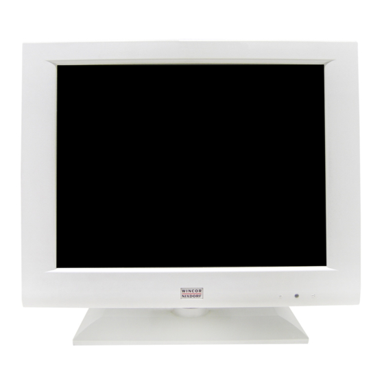
- Page 1 BA73A LCD TFT 15" (38.1 cm) Flat Screen User Manual...
- Page 2 Published by Wincor Nixdorf GmbH & Co. KG D-33094 Paderborn Bestell-Nr./Order No.: 01750038094A Printed in Singapore...
- Page 3 BA73A LCD TFT 15" Flat Screen User Manual Edition May 2001...
- Page 4 PCI Special Interest Group (SIG), USA ® BEETLE is a registered trademark of the Wincor Nixdorf GmbH & Co. KG All other trademarks are the property of their respective owners Copyright © Wincor Nixdorf GmbH & Co, KG, 2001 The reproduction, transmission or use of this document or its contents is not permitted without express authority.
-
Page 5: Table Of Contents
From Point-of-Sale to Point-of-Service ............1 Advantages at a Glance................2 Unpacking and checking the Delivery Unit ..........3 About this Manual..................3 BA73A Components ................. 4 Screen Module .................... 4 LCD-Controller -A/BA73A ................5 Capacative Touch Screen (Option) ............8 General...................... - Page 6 Installation ....................27 Installing the Controller in the BEETLE .............27 Connecting the Speaker Cable ...............29 Connecting the BA73A to the BEETLE /20 ..........30 Connecting the BA73A to the BEETLE /XL-II..........30 Connecting the BA73A to the PC ..............31 Connecting the BA73A to the BEETLE /M ..........31 The Jumper layout of the Celeron/Pentium III “D2"- board.....32...
- Page 7 Technical Data ..................48 Touch Screen (optional)................48 TFT/ LCD Screen ..................49 BA73A ....................... 50 Current Consumption ................51 LCD-Controller-A/BA73A ................ 51 Screen Module..................51 COM6/7/8 with Power Supply..............51 Power Consumption .................. 51 LCD-Controller-A/BA73A ................52 COM Board ....................53 Manufacturer’s Declaration and Approval..........
-
Page 8: Introduction
Touch Screen, loudspeaker and supply voltage. Optionally BA73A is equipped with a Touch Screen including a loudspea- ker. The BA73A can be applied in all trade market segments like specialist retailers, department stores, self-service stores, petrol stations or in restau- rants. -
Page 9: Advantages At A Glance
Advantages The low-energy, flickerfree and radiation-free colour monitor of the BA73A is an Active-Matrix-Display in TFT-technology (Thin Film Transistor). Therefore, it is well suited for multimedia applications as it offers brilliant colour representation, an excellent contrast ratio and a high display speed. -
Page 10: Unpacking And Checking The Delivery Unit
If damage has occurred during shipping or if the package contents do not match the delivery note, immediately inform your Wincor Nixdorf sales outlet. Transport the device only in its original packaging (to protect it against im- pact and shock). -
Page 11: Ba73A Components
BA73A Components Screen Module The screen module represents the main unit of the BA73A. It comprises of a TFT-LCD colour screen, the TFT-interface and an inverter that genera- tes the voltage for backlighting the screen. As an option the screens are available with Touch Screen including a loudspeaker. -
Page 12: Lcd-Controller -A/Ba73A
LCD-Controller -A/BA73A LCD-Controller-A/BA73A For the LCD display the LCD-Controller-A/BA73A (PCI) is needed and for the optional Touch function the COM board (ISA) is needed. Both boards have to be connected. The Controller and COM board need one slot with PCI and ISA interface. - Page 13 LCD-Controller-A/BA73A The LCD-Controller-A/BA73A is a plug-in-controller with a PCI-interface. There are two connections for a 40-pin MDR connector with integrated COM5 output a 9-pin DSUB female (for COM6) COM5 and COM6 are only ready for operation when the optional COM board is used.
- Page 14 Panel of LCD- Ccontroller-A/BA73A COM5/ COM6 Speaker Connector Jumper BIOS BA73A Connector COM6 resp. incl. COM5, LCD Interface "Touch In" and Loudspeaker MDR Connector (40-pin) DSUB Socket (9-pin) Board layout (LCD-Controller-A/BA73A) Jumper Settings of the LCD-Controller-A/BA73A: OPEN Closed Closed GB - 7...
-
Page 15: Capacative Touch Screen (Option)
Capacative Touch Screen (Option) General The TFT Touch Screen works according to the principle of a change in analog capacitance. It has a glass screen with a transparent, thin-film overlay on the surface. This is fully sealed and protected by a further layer of clear glass. -
Page 16: Touch Screen And Sleep Mode
Touch Screen Anti Reflective Etched Surface and protection ClearTek Glass Overcoat Conductive Coating Protective Noise Shield The programming interface of the screen is identical to the mouse inter- face. Touch Screen Touch Screen and Sleep Mode Using the Touch Screen with a BEETLE System, an entry via touch during sleep mode may lead to a faulty input. -
Page 17: How To Operate
Touch Screen How to Operate The Touch Screen responds to the slightest contact, therefore you do not have to apply much pressure when working with the screen. This does not only safe time, but is also kind to your joints! Touching the touch glass has the same effect as clicking the left mouse button. -
Page 18: I/O-Addresses Of Com Interfaces
COM Board I/O-Addresses of COM Interfaces COM Board The four COM interfaces of the COM board have the following I/O-addresses. Please refer to the table for the jumper settings. Address (Hex) 2E0 - 2E7 330 - 337 320 - 327 328 - 32F 338 - 33F 328 - 32F... - Page 19 COM Board The interrupts IRQ9 and IRQ10 are added for PC application only. For a correct reproduction of the interrupt signals it is necessary that the jumper IR9 to IR15 are not activated. To activate the interrupt request signal the corresponding jumper must be closed.
-
Page 20: Assignment Of Com Port Addresses And Interrupts
COM Board Assignment of COM port addresses and interrupts (installation details) Ensure that there is no conflict of hardware port addresses or interrupt requests (IRQs) used by your system and the COM Board! Essentially the AT COM Board has been designed to be configurable for a non-shared IRQ9, IRQ10, IRQ11, IRQ12, or IRQ15 for COM5 and a shared IRQ9, IRQ10, IRQ11, IRQ12, or IRQ15 for COM6,7,8 and even COM5. -
Page 21: Irq12, Most Likely Conflict Mouse Port Or Ps/2 Mouse
COM Board IRQ12, most likely conflict Mouse Port or PS/2 Mouse These types of mice are supported by Windows NT through the I8042PRT.SYS driver. The mouse usually has a (small) cylindric 6 pin connector. It seems that these types of mice mostly will use IRQ12. Some systems, however, allow to disable the mouse port in the BIOS Setup. -
Page 22: Using Shared Interrupts For Com Ports
COM Board The AT COM Board manual numbers the COM ports from 5 to 8. The ori- gin of this numbering is from the BEETLE, which has COM1 to COM4 on the motherboard. It is recommended for consistency, that you use this numbering also, regardless whether you have e.g. - Page 23 COM Board This will be impossible for hardware reasons! The problem is, that in such a case on the AT bus two different hardware instances would be fighting for the same IRQ! Refer to the technical information about your system for the details you need! If you configured COM ports to share a common interrupt and ‘Permit Share’...
-
Page 24: Using Shared Interrupts For Com Ports Under Windows 95
COM Board Using shared interrupts for COM ports under Windows 95 Under Windows 95, sharing COM ports doesn’t require special provisions other than correctly specifying the resources used in the Device Manager. However, in addition to avoid port address conflicts, you must ensure that no two different pieces of hardware on the AT bus are fighting for the same IRQ! Using COM ports under Windows 3.x... - Page 25 COM Board Interrupt Jumper IO Jumper IO 3 I 16 IO 1 Interrupt Request IR 9 IR11 IR15 IR10 IR12 COM 5 / COM 6 COM7 COM8 Board layout COM board GB - 18...
-
Page 26: Lcd-Tft Adapter A-Celeron/Pentium Iii
LCD-TFT Adapter A-Celeron LCD-TFT Adapter A-Celeron/Pentium III LCD-TFT Adapter A-Celeron If your BEETLE is equipped with a “D1" or ”D2" CPU the TFT adapter can be connected with the CPU without LCD-Controller-A and without COM board. The LCD TFT adapter-A is a submodule of the CPU which is necessary for the con- necting process. -
Page 27: Resistive Touch Screen (Option)
Resistive Touch Screen (Option) General The resistive TFT Touch Screen is constructed of a hard-coated polyester topsheet that is overlaid on a conductively-coated glass layer. Voltage is applied to the topsheet. As the user touches the screen, the topsheet com- presses into contact with the glass layer, and current flows to the four cor- ners in proportion to the distance from the edge. -
Page 28: How To Operate
Construction of the resistive Touch Screen: Hard-coated polyester topsheet Adhesive Glass substrate with spacer dots How to Operate Touching the touch screen has the same effect as clicking the left mouse button. You only need to apply a little pressure with the fingertip. In this re- sistive process not only fingertip contact is recognized. - Page 29 Cleaning Instructions Always turn off the system before cleaning. The surface of your Touch Screen should be cleaned with a water-based solvent or a non-abrasive cleaner.Do not use solvents containing acetic acid or methylene chloride. Use a soft, fine-meshed cloth to clean the surface. Dampen the cloth slightly and then clean the screen.
-
Page 30: Installing And Securing The Screen Into Place
Installing and Securing the Screen into Place The screen can be easily installed as a table top terminal. Securing into Place Remove the footed stand and screen element from the card- board packaging. Tilt the screen backwards. Turn the fastening screw on the screen with a crosstip screw- driver until the connec-... - Page 31 Securing into Place Now fasten the screw on the footed stand into place again using the crosstip screw- driver. Ensure that the screw is in the correct position. GB - 24...
-
Page 32: Adjustable Screen Angle
Adjustable Screen Angle Adjustable Screen Angle Adjustable Screen Angle The BA73A is fitted with a joint on the rear. You can optimize the angle of the screen depending on the viewing and lighting conditions. loose tight Use a screwdriver to... -
Page 33: Ergonomic Terminal Workplace
Ergonomic Terminal Workplace Ergonomic Terminal Workplace Ergonomic Terminal Workplace Please observe the following when setting up your terminal workplace: Avoid direct glaring and reflective glaring. Use the screen only in a controlled luminance surounding. Install the device with a viewing direction that is parallel to the windows. -
Page 34: Installation
Installation Installing the Controller in the BEETLE First ensure that the controller is switched off and the mains supply plug has been pulled out. Remove the housing upwards. Take care in doing so that you do not tilt or jam the housing in any way. - Page 35 Installing the Controller in the BEETLE Metal tracks Speaker connector In order to be able to install the LCD-Controller-A, you must first remove the metal panel that covers the free slots by loosening the screw. Set the jumper for the I/O addresses and the interrupt requests on the COM board.
-
Page 36: Connecting The Speaker Cable
BEETLE-CPU. BEETLE CPU Connecting the speaker cable If you do not connect the BA73A to a BEETLE-CPU but to another commercially available PC, please pay attention to the pin assignment of the speaker. A loudspeaker cable for a PC is not included in the delivery unit. -
Page 37: Connecting The Ba73A To The Beetle /20
Back of the BEETLE /20 Connecting the BA73A to the BEETLE /20 Connecting the BA73A to the BEETLE /XL-II Connection of the BA73A to a BEETLE /XL-II via the TFT-LCD Adapter A. Adapter DC24V 110-120 V / 2 A max 200-240 V / 1 A max Cashdr. -
Page 38: Connecting The Ba73A To The Pc
If you want to upgrade your BEETLE /M later, please read the section “Installing the TFT adapter" at the end of this chapter. If a TFT adapter-A is installed, a BA73A can be connected to the BEETLE /M without assigning a slot. The connection of the adapter and the display and the loudspeaker is effected via a 40-pin data cable. -
Page 39: The Jumper Layout Of The Celeron/Pentium Iii "D2"- Board
Jumper Layout The touch function with a LCD TFT adapter-A has to be activated via a jumper. The COM2 interface has to be covered and may no longer be used externally. The Jumper layout of the Celeron/Pentium III “D2"- board Jumper Layout GB - 32... -
Page 40: Jumper Setting
Jumper Layout Jumper Setting One jumper of the PT-jumpers is used to define the size of the TFT moni- tor: 12" and 15". 12" monitor connected 15" monitor connected The second and the third jumper are reserved for future applications. GB - 33... -
Page 41: The Jumper Layout Of The Celeron/Pentium Iii "D1"- Board
Jumper Layout The Jumper layout of the Celeron/Pentium III “D1"- board PS2/Mouse 32KB or 512KB 128KB BIOS XILINX 49F002T KYB/E PROG COM4* SuperI/O PC97317 AD1816AJS COM3* PCI/ISA IRQ I PT PCI-ONBOARD COM2*/I COM2* COM1 CELERON 82443BX 69000 CD-AUDIO AUDIO VGA/TFT DIMM0 DIMM1 LM80... -
Page 42: Com2 With Celeron/Pentium Iii Board ("D1"-Cpu)
After having set the necessary settings on S1, S2 and S3 in the case of using the touch function, continue according the following instructions. LCD Paneltype Settings for BA73A Paneltype 0: XGA (1024 x 768), set ex works. Interrupt... -
Page 43: Connecting The Cable
Connecting Cable Connecting the cable The data cable is to be connected with the 50-pin connector of the TFT adapter. Take care that the thickening of the cable (Ferrit) is principally po- sitioned on the side of the TFT adapter. Connecting Cable Battery COM7... -
Page 44: Installing A Lcd-Tft Adapter A
TFT adapter Now plug in the cable until it snaps in (see il- lustration). When removing the cable press on the connector release. Installing a LCD-TFT Adapter A Never open the BEETLE when the circuit is switched on. Plug in the TFT adapt- er on the CPU module via the sub module as shown in the illustrati-... -
Page 45: Inserting The Cable
, and then remove it from the guide rail. PULL PULL Insert the 40-pin BA73A cable of the keyboard. The cable will be carried in a cur- ve from the small co- ver of the screen module to the cable co- ver. -
Page 46: Releasing The Cable Connection
Releasing the Cable Connection Releasing the Cable Connection Releasing the Cable Connection Never remove a cable from a connector socket by simply pulling on the cable. Always remove the cable by the connector housing. Please follow the instructions below when removing cables: Turn off all switches to the mains and electrical equipment. -
Page 47: Software Installation
Then you can allocate the resources and set the cor- responding jumper configuration on the COM board. The BA73A is supported by the operating systems MS DOS; Windows 98, Windows 2000, Windows Me and Windows NT. -
Page 48: Software Interfaces
Software Interfaces Touch Screen Touching the screen corresponds to press the left mouse key. The touch screen programming interface is identical to that of the mouse interface. Touch Screen and Sleep Mode Using the Touch Screen with a BEETLE Pentium CPU, an entry via touch during sleep mode may lead to a faulty input. -
Page 49: Automated Logic Diagram (Ald) And Pin Assignments
Automated Logic Diagram (ALD) and Pin Assignments Bildschirmm Screen module Inverter for two Backlights TFT-Interface TFT-Display Touch Screen (Option) Touch Screen Controller (Option) Loudspeaker (Option) Signals: TFT-PLINK, COM5, Loudspeaker (Option) 40pin. MDR LCD-Controller-A (PCI Interface) 40pin MDR COM8* COM Board (ISA Interface) COM6 COM7* FREE ISA-Slot... -
Page 50: Interface
Automated Logic Diagram Interface Automated Logic Diagram The LCD interface is connected to the TFT controller via a 40-pin cable. The inverter, LCD display, touch screen controller and beeper are connec- ted to this interface in the TFT screen module. Inverter (High-Voltage Generator) Inside the TFT, the high voltage needed for backlighting the LCD display is generated by the inverter! -
Page 51: Pin Assignments
Pin Assignment Pin Assignments BA73A Connectors of the 40-pin TFT Interface Pin Assignment PIN # Signal PIN # Signal HUOUT RXCN RXCP P5VLCD P5VLCD RX0N RX0P FPEN RxD1 TxD1 P12VLCD P12VLCD RXIN RXIP P12VLCD RX2N RX2P GB - 44... -
Page 52: Com 6 Interface Of The Lcd-Controller-A/Ba73A
Pin Assignments COM 6 Interface of the LCD-Controller-A/BA73A PIN # signal P12VF RxD2 TxD2 DTR2 GNDF1 DSR2 RTS2 CTS2 P5VF Internal Speaker Connector for Controller and BEETLE-CPU PIN # signal n.c. n.c. n.c. HUIN COM7 and COM8 Interfaces of the LCD-Controller-A... -
Page 53: Internal Connecting Socket
Pin Assignments Internal Connecting Socket PIN# COM7 COM8 P5VF P5VF GNDF GNDF DCD3 DCD4 CTS3 CTS4 DTR3 DTR4 RTS3 RTS4 TxD3 TxD4 DSR3 DSR4 RxD3 RxD4 P12VF P12VF GNDF GNDF GB - 46... -
Page 54: External Connecting Socket
Pin Assignments External Connecting Socket PIN# with power supply w/o power supply +12V GB - 47... -
Page 55: Technical Data
Technical Data The following operating conditions are valid for a BA73A TFT that is fitted with all the available modules. IEC 721 3/3 Class 3K3 Climate class Operating +5° C - + 40° C temperature 5% - 85% Absolute humidity 1g/m³ - 25g/m³... -
Page 56: Tft/ Lcd Screen
Colour RGB 16, 256, 64k 0.30 mm x 0.30 mm Pixel Format 5V from interface Power Supply TFT, 18 Bit LCD Technology BA73A (with/ w/o Touch) approx. Brightness 190/230 cd/m (Center LCD) Reading Angle +/- 70° right/left +/- 25 °... -
Page 57: Ba73A
BA73A BA73A Screen size 15" (38.1 cm) Active screen size 304.1mm x 228.1mm (horizontal x vertical) Cable length 3 m / 5m Dimension Display Housing Dimensions without foot. Stand/Hinge 390 x 305 x 57 (W x H X D in mm) Dimension Display Housing with foot. -
Page 58: Current Consumption
0 mA +12V (Standby Mode) 1000 mA +5V (Normal Mode) 300 mA +5V (Standby Mode) COM6/7/8 with Power Supply max. 900 mA + 12V max. 300 mA + 5V Power Consumption LCD-Controller-A/BA73A / COM Board: 2.5 W GB - 51... -
Page 59: Lcd-Controller-A/Ba73A
LCD-Controller-A/BA73A LCD-Controller-A/BA73A Interface PCI, 32 Bit Mode Resolution 1024 x 768 (High Color) 2 MB Image Repeat Memory Screen Memory Text mode B800H- BFFFH A000H- AFFFH Page mode according PCI Linear mode BIOS 40 kB, Address C000H-C9FFFH 1) 40-pin MDR connector for LCD... -
Page 60: Com Board
TFT controller Connection for COM7/8 and COM7*/8* Interface for BEETLE /XL , /M and /20, COM7 and COM8 PC standard or Wincor Nixdorf retail (optional) standard with connector adapter for 9pin DSUB connector or socket GB - 53... -
Page 61: Manufacturer's Declaration And Approval
Manufacturer’s Declaration and Approval General Authorization This device fulfills the requirements of the EEC standard 89/336/EWG “Electromagnetic Compatibility”. Therefore, you will find the CE mark on the device or packaging. FCC-Class A Declaration This equipment has been tested and found to comply with the limits for a Class A digital device, pursuant to part 15 of the FCC Rules. -
Page 62: Tested Safety
UL- symbol. User Information Wincor Nixdorf GmbH & Co. KG (WN) does not accept responsibility for ra- dio and TV interference and faults that are caused by unauthorized chan- ges that have been made to the devices. Furthermore, cables or other devices that have not been approved by WN may not be connected to the device. -
Page 63: Safety Instructions
BEETLE or PC should be removed, and the Wincor Nixdorf customer service should be contacted. If the LCD display element is broken and the liquid crystal solution... -
Page 64: Instructions For Maintenance
Wincor Nixdorf customer service. Recycling Environmental protection does not begin when the time has come to dispo- se of the BA73A; it begins with the manufacturer. This product was de- signed according to our internal norm “Environmental conscious product design and development”. - Page 65 Wincor Nixdorf guarantees the environmentally safe disposal of these parts in a Recycling Center, which is certified pursuant to ISO 9001. So don’t simply throw your BA73A on the scrap heap when it has served its time, but take advantage of the environmentally smart up-to-date...
-
Page 66: Appendix
Appendix Abbreviation Index ASCII American Standard Code for Information Interchange Advanced Technology BIOS Basic Input Output System Cold cathode Fluorescent Lamp Communication Port Central Processing Unit Cathode Ray Tube DSTN Double Super Twisted Nematic, LCD Technology Hexadecimal Value Hardware Industrial Standard Architecture International Standards Organisation Local Area Network Line Printer...
Need help?
Do you have a question about the BA73A and is the answer not in the manual?
Questions and answers