Table of Contents
Advertisement
Quick Links
Advertisement
Table of Contents

Related Manuals for Wincor Nixdorf BA69W


Summary of Contents for Wincor Nixdorf BA69W
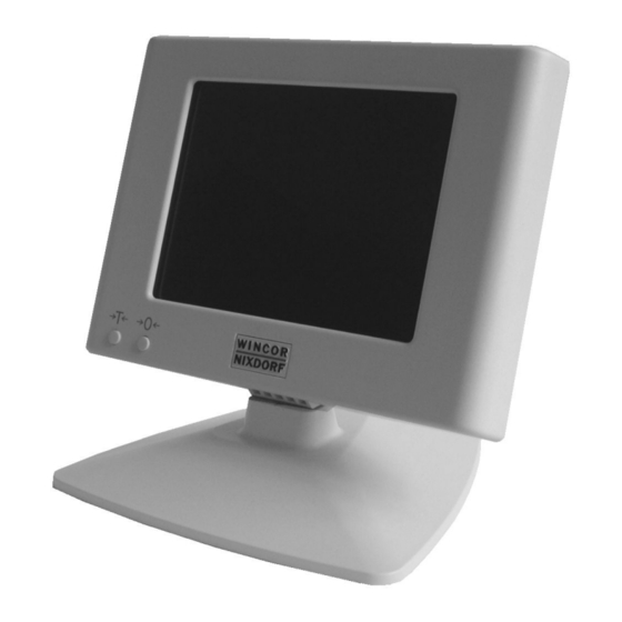
- Page 1 BA69W LC-Display 5,7’‘ black/white User Guide...
- Page 2 BA69W User Guide Edition August 2004...
- Page 3 PENTIUM® is a registered trademark of Intel Corporation MS-DOS® is a registered trademark of the Microsoft Corporation BEETLE® is a registered trademark of Wincor Nixdorf International GmbH Copyright © Wincor Nixdorf International GmbH, 2004 The reproduction, transmission or use of this document or its contents is not permitted without express authority.
-
Page 4: Table Of Contents
Cleaning the BA69W ..................6 Recycling the BA69W.................7 Before assembling ...................8 Unpacking and checking the packing list ...........8 Wiring connections for the BA69W ............9 Data cable plug connection..............10 Connection to the VGA/4 controller MUX ..........11 Connection to the VGA/4 embedded scale controller ......11 Disconnecting the cable.................11... - Page 5 Appendix ....................33 Technical data BA69W................33 VGA/4 Controller MUX ................34 VGA/4 Embedded Scale Controller ............34 Hardware design ..................35 LCD Display ...................36 Inverter....................37 VGA/4 interface..................37 VGA/4 controller MUX................37 VGA/4 embedded scale controller ............37 Abbrevations ....................38...
-
Page 6: Manufacturer´s Certification
Manufacturer´s Certification The device complies with the requirements of the EEC directive 891336/EEC with regard to ‘Electromagnetic compatibilily". Therefore, you will find the CE mark on the device or packaging. GB - 1... -
Page 7: Important Notes
Important notes The display BA69W conforms to the current safety standards for data processing equipment. If this device is taken from a cold environment into the operating room, moisture condensation may form. The device must be abso- lutely dry before being put into service; an acclimatization period of at least two hours must therefore be observed. -
Page 8: Warranty
Warranty Wincor Nixdorf (WN) guarantees a limited warranty engagement for 12 months beginning with the date of purchasing. This warranty engage- ment covers all those damages which occur despite a normal use of the product. -
Page 9: Introduction
You may select between the version with its own base stand, a tube assembly, or assembly on the TA85 keyboard. There are two buttons on the BA69W for tare and zero setting. These buttons are necessary for the scale solution. -
Page 10: What Does Vga/4 Mean
It should be noted here that, in comparison with a standard VGA screen, the entire right half of the screen is not visible. As a result, standard applications cannot be displayed at the BA69W. You can only use software which has been appropriately adapted. -
Page 11: About The Manual
Clean your BA69W at regular intervals with a cleaner which is suitable for plastic surfaces. This cleaner may be ordered from Wincor Nixdorf-Plus. -
Page 12: Recycling The Ba69W
Nlxdorf guarantees the environmentally safe disposal of these parts in a Recycling Center, which is certified pursuant to ISO 9001. So don’t simply throw your BA69W an the scrap heap when it has ser- ved its time, but take advantage of the environmentally smart,... -
Page 13: Before Assembling
If you determine that there is shipping damage or discrepancies bet- ween the packing list and the bill of delivery, please inform your con- tract affiliate or the sales office of Wincor Nixdorf immediately. We recommend that you keep the original packaging in case it should be necessary to ship the equipment again (protection from shock and impact). -
Page 14: Wiring Connections For The Ba69W
Be sure that the power plug of the cash-register system has been disconnected. Plug the data cable in the BA69W and the jack of the controller on the cash-register system. Plug in the power cable of the cash-register system into the socket again. -
Page 15: Data Cable Plug Connection
Grasp the cable cover panel at the locations marked by the arrows. Pull the cable cover panel downward and remove it to the rear. Push the data cable into the BA69W display as shown in the illustration until you hear an audible click as it engages. Then replace the cable cover panel. -
Page 16: Connection To The Vga/4 Controller Mux
Connection to the VGA/4 controller MUX Two liquid-crystal displays can be connected to the supplied controller. The BA69W display is always connected at the LCD2 jack. Insert the data cable into the corresponding jack until the plug connector enga- ges audibly. -
Page 17: Assembly
Assembly Base stand Insert the display in the base stand so that the groove (arrow) advan- ces into the guide of the base stand and audibly engages. GB - 12... - Page 18 Connect the plug connector on the rear of the BA69W and secure the cable cover panel. Connect the data cable to the cash-register system. GB - 13...
-
Page 19: Tube Assembly
First thread the cable for the display through the two tubes as shown in the illustration. There is a square recess in the short tube which is pro- vided especially for the smaller plug connector of the BA69W. The plug connector can easily be guided from below through this recess. - Page 20 Now insert the display so that the groove (arrow) moves into in the guide of the support bracket and engages. Secure the plug connector of the data cable as described in the chap- ter “Wire connections for the BA69W” (page 10). GB - 15...
-
Page 21: Ta85 Keyboard
Mount the display on the keyboard (refer to the illustration). Secure the plug connectors of the data cable as described in the chap- ter “Wire connections for the BA69W”. GB - 16... -
Page 22: Adjustment Options
Adjustment options Rotating and tilting You can tilt the display up to 45 degrees to the rear and 10 degrees forward. With the tube assembly, the display can also be rotated by up to 330 degrees. GB - 17... -
Page 23: Adjusting The Contrast
Adjusting the contrast You will find the rotary knob for the contrast setting on the rear of the display (refer to the enlarged section of the illustration). GB - 18... -
Page 24: Controller
Controller VGA/4 Controller MUX The controller is suitable for connecting a combined POS and scale display. The BA69W display is always connected at the LCD2 jack. This controller is used when the embedded scale controll has no VGA/4 interface. Below: Illustration of the controller mask panel. -
Page 25: Vga/4 Embedded Scale Controller
VGA/4 Embedded Scale Controller The BA69W display is connected at the BA69W jack. Insert the data cable into the corresponding jack until the plug connector engages au- dibly. Below is an illustration of the controller mask panel. COM interface Protection... -
Page 26: Replacing/Cleaning The Glass Cover
Replacing/Cleaning the glass cover If the protective glass cover is scratched or cracked, you should repla- ce it. Also, proceed as follows if you wish to clean the cover from the inside. First switch the cash-register system off and disconnect the power plug. - Page 27 Disconnect the cable: To disconnect the cable, press on the releases on the plug connector marked by the arrows and pull the connector downwards. Now press the two release tabs on the rear of the display downwards. GB - 22...
- Page 28 The display cover can now be rotated forward. Release the glass cover by pulling the plastic section gently outward at the location marked (1) while simultaneously pressing the glass cover (2) out from the bottom. In order to avoid fingerprints on the inside of the new glass cover, grasp it only on the edges.
- Page 29 Avoid touching the display screen in the following steps. Insert the new protective cover below the clip retainers shown in the illustration (below) and then press it carefully past the opposite alignment retainer. Then position the display housing on the screen and close it until the lower locking tabs audibly engage.
-
Page 30: Replacing The Backlighting
Replacing the backlighting If the backlighting should malfunction, you can replace it with a few easy steps. First switch the cash-register system off and disconnect the power plug. Then remove the cable cover panel on the rear of the display. A damaged backlighting is not covered by warranty engagement. - Page 31 Disconnect the cable. To disconnect the cable, press on the releases on the plug connector marked by the arrows and pull the connector downward. Now press the two release tabs for the front section on the rear of the display downward (refer to the illustration). Avoid touching the display screen in the following steps.
- Page 32 The cover of the display can now be rotated forward. Pull the entire display upward and out of the support bracket and place it carefully on a smooth, clean and soft work surface with the screen side facing downward. When the front cover is removed, grasp the display only on the rear plastic housing.
- Page 33 Press the retainers on the rear panel and remove the panel toward the top. GB - 28...
- Page 34 You will see the cable for the backlighting on the left side of the hou- sing next to the inverter. First lift the cable from the x-support bracket and then from the y-support bracket so that the cable is freed. Pull out the plug connector (1) for the backlighting on the inverter.
- Page 35 Now remove the cable from the channel. Then fold the three marked tabs upward and remove the backlighting on the cable vertically up- ward. GB - 30...
- Page 36 Do not touch the new backlighting on the glass body. Insert the new backlighting and lock it in place by folding the tabs back. Position the cable in the cable channel (1) and around the cable retai- ner (2). Following that, plug the plug connector into the inverter (3) and route the cable in front of the second cable retainer (4).
-
Page 37: Appendix
Appendix Technical data BA69W Technology STN (Super Twisted Nematic) Type 1/4 VGA monochrome Size 5,7" Resolution 320 (H) x 240 (V) pixel Visible area 120 (H) x 89 (V) mm Pixel format 0,36 x 0,36 mm Brightness approx. 120 cd Contrast approx. -
Page 38: Vga/4 Embedded Scale Controller
VGA/4 Controller MUX System interface PCI-Frequency max. 33 MHz 32 Bit VGA Standard Fully compatible Connectors at bracket 1. 26pol MDR for LCD1 with power supply 12 V 2. 26pol MDR für LCD2 iwith power supply 12 V Current consumption 5V @ 400 mA VGA/4 Embedded Scale Controller System interface... -
Page 39: Hardware Design
Hardware design The block diagram shows the functions and the internal and external con- nections of the BA69W. VGA/4 LCD-Modul Inverter for CFL backlighting VGA/4 interface STN display 5,7" 320 x 240 interface tare, zero setting Contrast adjustment LCD Display... -
Page 40: Inverter
Inverter VGA/4 LCD-Modul Inverter for CFL backlighting VGA/4 interface STN display 5,7" 320 x 240 interface Tare, zero setting Contrast adjustment Signals: STN-LCD, POWER SUPPLY P12V, Tare and zero setting VGA/4 Embedded Scale Controller DC24V 100-120 V / 2 A max CASHDR ONLY 200-240 V / 1 A max LPT1... -
Page 41: Vga/4 Controller Mux
The controller is equipped with a 16 bit microprocessor, a graphic IC with LCD interface, a firmware PROM, a static RAM and a UART. The LCD signals for the BA69W will be transferred via a 26-pin connector. GB - 36... -
Page 42: Abbrevations
Abbrevations Cold cathode Fluorescent Lamp Communication Port canada Underwriters Laboratories EPROM Erasable Programmable Read Only Memory Tested safety Graphic User Interface International Standardization Organization Liquid Crystal Display Mini Delta Ribbon (connector family of 3M) One Time programmable (EPROM type) Peripheral Component Interconnect Quality safety Random Access Memory Read Only Memory...
Need help?
Do you have a question about the BA69W and is the answer not in the manual?
Questions and answers