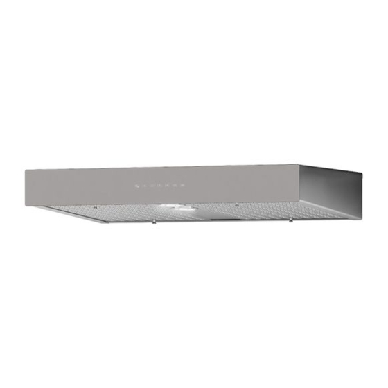
Venmar Connaisseure C700 SERIES Installation Instructions Manual
Hide thumbs
Also See for Connaisseure C700 SERIES:
- Installation instructions manual (9 pages) ,
- Installation instructions manual (3 pages)
Table of Contents
Advertisement
Quick Links
INSTALLATION INSTRUCTIONS
HB0116
C700 SERIES
INTENDED FOR DOMESTIC COOKING ONLY
!
!
READ AND SAVE THESE INSTRUCTIONS
INSTALLER: LEAVE THIS MANUAL WITH HOMEOWNER.
HOMEOWNER: USE AND CARE INFORMATION
ON PAGES 10
12.
TO
Venmar Ventilation Inc., 550 Lemire Blvd., Drummondville QC J2C 7W9
1-800-567-3855
REGISTER YOUR PRODUCT ONLINE AT: www.bnv.ca
For additional information, visit
www.venmar.ca or www.ispira.ca
SV09627 rev. 04
Advertisement
Table of Contents

Related Manuals for Venmar Connaisseure C700 SERIES


Summary of Contents for Venmar Connaisseure C700 SERIES
-
Page 1: Installation Instructions
READ AND SAVE THESE INSTRUCTIONS INSTALLER: LEAVE THIS MANUAL WITH HOMEOWNER. HOMEOWNER: USE AND CARE INFORMATION ON PAGES 10 Venmar Ventilation Inc., 550 Lemire Blvd., Drummondville QC J2C 7W9 1-800-567-3855 REGISTER YOUR PRODUCT ONLINE AT: www.bnv.ca For additional information, visit www.venmar.ca or www.ispira.ca... - Page 2 WARNING WARNING TO REDUCE THE RISK OF FIRE, ELECTRIC TO REDUCE THE RISK OF INJURY TO SHOCK OR INJURY TO PERSONS, OBSERVE PERSONS IN THE EVENT OF A RANGE TOP THE FOLLOWING: GREASE FIRE, OBSERVE THE FOLLOWING*: 1. Use this unit only in the manner intended 1.
-
Page 3: Table Of Contents
TABLE OF CONTENTS ..................... 3 NSTALL DUCTWORK 2. P ..................4 REPARE THE INSTALLATION 3. P ....................5 REPARE THE HOOD 4. I ) ................ 6 NSTALL GLASS PANEL WG MODELS ONLY 5. I ................... 6-7 NSTALL THE ADAPTER DAMPER 6. - Page 4 PREPARE INSTALLATION WARNING When performing installation, servicing or cleaning the unit, it is recommended to wear safety glasses and gloves. NOTE: Before proceeding to the installation, check the contents of the box. If items are missing or damaged, contact the manufacturer. Make sure that the following items are included: - Hood - Installation manual...
-
Page 5: Prepare The Hood
PREPARE THE HOOD 3.1 Lay the hood on a table. Use a piece of cardboard to avoid damaging the table or the hood. Remove tape on filters. Lift filters by pushing them towards the back and rotate, then set the filters aside. HD0412 3.2 Remove the bottom panel 10 retaining screws and set aside. -
Page 6: Nstall Glass Panel
INSTALL GLASS PANEL ( WG MODELS ONLY The WG hood models decorative glass panel is sold separately and has to be installed before completing the hood installation. 4.1 Remove glass panel from its packaging. Remove glass panel nuts (factory installed) from both studs and set aside. 4.2 Insert glass panel studs in hood front holes. -
Page 7: Damper
5. INSTALL THE ADAPTER/DAMPER ( ALL MODELS CONT ORIZONTAL ISCHARGE CONT Press the metal shutoff plate on a flat surface to completely flatten bent flange. HD0415 Using both screws previously removed, install the metal shutoff plate on top of the hood. HO0186 Fold down the foldable flange of the adapter/ damper. -
Page 8: Install The Hood
6. INSTALL THE HOOD 6.1 Run power cable installation location. Position the hood in its intended location. Using a pen, mark the position of the screws (as shown at right). Remove the hood. HD0413 6.2 Install the first four no. 8 x 1/2’’ screws, leaving a 1/8’’ gap (do not install screws nos. 5, 6 and 7 yet). -
Page 9: Einstall Blower Wheels And Bottom Panel
8. REINSTALL BLOWER WHEELS AND BOTTOM PANEL CAUTION When reinstalling the blower wheels, make sure the small tab will fit into one hole of the motors. 8.1 Reinstall blower wheels: Using both hands gently push on each blower wheel until secured. HO0175 8.2 Insert bottom panel in the back of the hood. -
Page 10: Light Bulbs
10. LIGHT BULBS This range hood requires two 120 V, 50 W max., type MR16 with GU10 base, shielded halogen bulbs (included). WARNING Do not touch lamps during or soon after operation. Burns may occur. In order to prevent the risk of personal injury, only install shielded halogen lamps. Also, never install a cool beam, a dichroïc lamp, a lamp not suitable for use in recessed luminaires or identified for use in enclosed fixtures. -
Page 11: Operation
11. CARE ( CONT LASS PANEL Hot water with mild soap or glass cleaner is all that is usually needed. When using mild soap, rinse with clear water. Wipe dry with a clean, soft cloth to avoid water marks. Avoid when choosing a detergent: - Any cleaners that contain bleach will attack stainless steel. - Page 12 12. OPERATION ( CONT C. M ON/OFF: ASTER When blower and lights are off, press this button to turn the hood on to the last memorized speed level and light intensity. If there are no memorized speed level and light intensity, speed will be set at level 1 and light intensity at 4.
-
Page 13: Wiring Diagram
13. WIRING DIAGRAM WARNING Risk of electric shock. Electrical wiring must be done by qualified personnel in accordance with all applicable codes and standards. Before connecting wires, switch power off at service panel and lock service disconnecting means to prevent power from being switched on accidentally. -
Page 14: Service Parts
14. SERVICE PARTS HL0151... -
Page 15: S Ervice Parts
ARTS AND EPAIRS In order to ensure your unit remains in good working condition, you must use Venmar Ventilation Inc. genuine replacement parts only. Venmar Ventilation Inc. genuine replacement parts are specially designed for each unit and are manufactured to comply with all the applicable certification standards and maintain a high standard of safety. -
Page 16: Warranty
C700 SERIES RANGE HOOD NOR HELD RESPONSIBLE FOR SUBSEQUENT DAMAGE OR INCIDENT. During the period stated above, Venmar Ventilation Inc. will, at its option, repair or replace without charge any product or part which is found to be defective under normal use and service. THIS WARRANTY DOES NOT EXTEND TO BULBS, FUSE, FILTERS, DUCTS, ROOF CAPS, WALL CAPS AND OTHER ACCESSORIES FOR DUCTING.
Need help?
Do you have a question about the Connaisseure C700 SERIES and is the answer not in the manual?
Questions and answers