Table of Contents
Advertisement
Quick Links
INSTALLATION INSTRUCTIONS
HB0046
CC700 SERIES
INTENDED FOR DOMESTIC COOKING ONLY
!
!
READ AND SAVE THESE INSTRUCTIONS
INSTALLER: LEAVE THIS MANUAL WITH HOMEOWNER.
HOMEOWNER: USE AND CARE INFORMATION
ON PAGES 19 TO 20.
Venmar Ventilation Inc., 550 Lemire Blvd., Drummondville QC J2C 7W9
1-800-567-3855
REGISTER YOUR PRODUCT ON LINE AT: www.bnv.ca
For additional information, visit
www.venmar.ca or www.ispira.ca
SV09628 rev. 03
Advertisement
Table of Contents

Subscribe to Our Youtube Channel
Related Manuals for Venmar CC700 SERIES


Summary of Contents for Venmar CC700 SERIES
-
Page 1: Installation Instructions
READ AND SAVE THESE INSTRUCTIONS INSTALLER: LEAVE THIS MANUAL WITH HOMEOWNER. HOMEOWNER: USE AND CARE INFORMATION ON PAGES 19 TO 20. Venmar Ventilation Inc., 550 Lemire Blvd., Drummondville QC J2C 7W9 1-800-567-3855 REGISTER YOUR PRODUCT ON LINE AT: www.bnv.ca For additional information, visit www.venmar.ca or www.ispira.ca... - Page 2 Cherries Jubilee, Peppercorn Beef Flambé). To reduce the risk of fire and electrical shock, the Clean ventilating fans frequently. Grease should Venmar Connaisseur CC700 Series models should only be installed with their own built-in not be allowed to accumulate on fans, filters or blower.
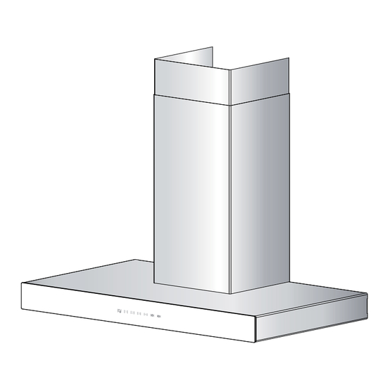
- Page 3 - CC700 SERIES RANGE HOOD SYSTEM - ODEL ODEL ODEL ODEL ODEL (3¼” 10” (6” R (3¼” 10” OUND OOF CAP WALL CAP OOF CAP 6” R ODEL OUND 3¼” 10” OPTIONAL ADJUSTABLE ELBOW ELBOW OPTIONAL PPER DECORATIVE FLUE ODEL (3¼”...
-
Page 4: Table Of Contents
TABLE OF CONTENTS ........................4 NSTALL DUCTWORK ......................5-6 REPARE THE INSTALLATION ......................6 EMOVE BAFFLE FILTERS )..................7 NSTALL GLASS PANEL WG MODELS ONLY .........................8 HOOSE THE OPENING ) ...............8 LOWER REMOVAL HORIZONTAL DISCHARGE ONLY .....................10-11 NSTALL ADAPTER DAMPER ......................11-12 IRING INSTALLATION .....................12 NSTALL HOOD MOUNTING BRACKET 10. -
Page 5: Prepare The Installation
2. PREPARE THE INSTALLATION WARNING When performing installation, servicing or cleaning the unit, it is recommended to wear safety glasses and gloves. NOTE: Before proceeding to the installation, check the contents of the box. If items are missing or damaged, contact the manufacturer. Make sure that the following items are included: - Hood - Accessories •... -
Page 6: Remove Baffle Filters
2. PREPARE THE INSTALLATION ( ’ CONT Refer to illustrations below to locate duct opening for vertical discharge. 3¼" 10" A ERTICAL DISCHARGE USING DAPTER AMPER 30” ⁄ ” WIDTH HOOD 36” ⁄ ” WIDTH HOOD 7/8” ⁄ ” 9¾” HK0060A 6"... -
Page 7: Install Glass Panel
4. INSTALL GLASS PANEL ( WG MODELS ONLY The WG hood models decorative glass panels are sold separately and have to be installed before completing the hood installation. CREW OCATIONS 1. Using a Robertson or a Phillips no. 2 screwdriver, remove the 4 electrical compartment cover... -
Page 8: Blower Removal
6. BLOWER REMOVAL ( HORIZONTAL DISCHARGE ONLY The CC700 Series range hoods are factory shipped with the blower mounted for a vertical discharge configuration. For a horizontal discharge configuration, disassemble the blower from the inner top of the hood by following the steps below. It will be assembled to the inner back of the hood once the hood is mounted on the wall. - Page 9 6. BLOWER REMOVAL ( ’ HORIZONTAL DISCHARGE ONLY CONT CREW OCATIONS SAME ON BOTH SIDES 2. Disconnect both light assemblies electrical harnesses from light connectors. Using a Robertson or a Phillips no. 2 screwdriver, remove the 6 light panel retaining screws (only 3 out of 6 screws illustrated at right).
-
Page 10: Install Adapter/Damper
6. BLOWER REMOVAL ( ’ HORIZONTAL DISCHARGE ONLY CONT 5. Using a 5/16” socket, or a Robertson or a Phillips no. 2 screwdriver, remove all blower mounting screws from the inner top of the hood. Set blower and screws aside. IGHT OUNTING OUNTING... -
Page 11: Wiring Installation
INSTALL ADAPTER/DAMPER ( ’ CONT (3¼" 10" A ERTICAL DISCHARGE DAPTER AMPER CREW OCATIONS Mount the 3¼" x 10" adapter/damper to the top of the hood using 2 no. 8 x 3/8” screws (included). Seal the adapter/damper to the hood using metal foil duct tape. HJ0065 (6"... -
Page 12: Install Hood Mounting Bracket
8. WIRING INSTALLATION ( ’ CONT Position the outlet within the space covered by the decorative flue. Place the outlet at a maximum distance of 24” (from where the cord exits from the hood). The center of the outlet must be positioned at 2¾” from the center of the future hood location (as illustrated at right). -
Page 13: Install Upper Flue Mounting Bracket
10. INSTALL UPPER FLUE MOUNTING BRACKET Center the upper flue mounting EILING bracket with the center line previously drawn in step 9 and place it flush with the ceiling. Use the upper flue mounting bracket as a template to HD0377 OUNTING BRACKET mark the position of its FLUSH WITH CEILING... -
Page 14: Reinstall Blower
12. REINSTALL BLOWER ( HORIZONTAL DISCHARGE ONLY 1. Position the blower on the back wall discharge. Secure the blower to the hood using a 5/16” socket, or a Robertson or a Phillips no. 2 screwdriver and the 4 previously removed screws. NOTE: In order to ease installation, before mounting the blower, prepare the screw holes by... -
Page 15: Prepare Decorative Flue
14. PREPARE DECORATIVE FLUE 1. Remove protective plastic film covering the lower flue only. 2. Peel off both corners at the top of the upper flue. 3. Position the lower flue rear notches down. 4. Gently slide upper flue inside lower flue. NOTE: Both lower and upper flues are included with hood,... -
Page 16: Reinstall Baffle Filters
15. INSTALL DECORATIVE FLUE ( ’ CONT PPER FLUE MOUNTING BRACKET RONT VIEW 3. Slide up the upper flue until it is aligned with its mounting bracket. The bracket PPER must be inside the flue. Secure the upper FLUE flue to its bracket using 2 no. 8 x 1/2” screws (included). -
Page 17: Optional Under Cabinet Installation
17. OPTIONAL UNDER CABINET INSTALLATION Although this is a chimney range hood, it can also be installed under a cabinet without its chimney. Following is our recommended optional under-cabinet installation. HB0118 1. Follow steps presented in sections 1 to 8 on pages 5 to 10. 2. -
Page 18: Light Bulbs
17. OPTIONAL UNDER CABINET INSTALLATION ( ’ CONT 5. Plug hood power cord into the outlet. HE0124 6. Finalise the installation by following step 16 on page 16. 18. LIGHT BULBS his range hood requires two 120 V, 50 W max., type MR16 with GU10 base, shielded halogen bulbs (included). -
Page 19: Care
19. CARE WARNING Before servicing or cleaning the unit, switch power off at service panel and lock service panel to prevent power from being switched on accidentally. When the service disconnecting means cannot be locked, securely fasten a prominent warning device, such as a tag, to the service panel. AFFLE ILTERS Baffle filters should be cleaned monthly. -
Page 20: O Peration
20. OPERATION ( ’ CONT HC0052 A. D ELAY UTTON ONTROL OUBLE UNCTION UTTON i. When a blower speed is selected, press this button to activate the delay function. The delay button will light to its high intensity, then to its mid intensity to indicate this function is activated; the selected blower speed button will alternate every 2 seconds from its high intensity to its mid intensity. -
Page 21: Wiring Diagram
To contact Venmar Ventilation Inc. warranty service call 1-800-567-3855 in Canada. In order to qualify for a warranty claim, the owner of a Venmar Connaisseur CC700 Series range hood must have the model and serial number along with a proof of the original purchase date. At the time of requesting service, describe the nature of any defect in the product or part. -
Page 22: Service Parts
Venmar Ventilation Inc. recommends to contact a certified service depot for all replacement parts and repairs.
Need help?
Do you have a question about the CC700 SERIES and is the answer not in the manual?
Questions and answers