Graco Ultra 395 Operation Manual
Electric airless sprayers
Hide thumbs
Also See for Ultra 395:
- Operation, parts (56 pages) ,
- Operation manual (36 pages) ,
- Repair manual (33 pages)
Table of Contents
Advertisement
Operation
Electric Airless Sprayers
Important Safety Instructions.
instructions.
3300 psi (227 bar, 22.7 MPa) Maximum Working Pressure
Ultra
Ultimate Nova
Super Nova
ST Max
- For the application of architectural paints and coatings -
Read all warnings and instructions in this manual. Save these
ti2399a
TM
395/495/595
TM
395
TM
495/595
TM
395/495/595
ti7374a
TM
UltraMax II
490/495/595
TM
Ultimate MX II
490/495/595
TM
ST Max II
490/495/595
309665L
EN
Advertisement
Table of Contents

Related Manuals for Graco Ultra 395


Summary of Contents for Graco Ultra 395
- Page 1 Operation 309665L Electric Airless Sprayers - For the application of architectural paints and coatings - Important Safety Instructions. Read all warnings and instructions in this manual. Save these instructions. 3300 psi (227 bar, 22.7 MPa) Maximum Working Pressure ti7374a ti2399a Ultra 395/495/595 UltraMax II...
- Page 2 Models Models Model Ultra 395 233960 233961 233962 Ultimate Nova 395 826014 Ultra 495 233966 233967 233968 Super Nova 495 826017 826018 826019 Ultra 595 234490 234435 Super Nova 595 826052 826046 Ultra Max II 490 249911 249913 249914 Ultimate MX II 490...
-
Page 3: Fire And Explosion Hazard
Warnings Warnings The following are general warnings related to the setup, use, grounding, maintenance and repair of this equipment. Additional, more sepcific warnings may be found throughout the body of this manual where applicable. Symbols appearing in the body of the manual refer to these general warnings. When these symbols appear throughout the manual, refer back to these pages for a description of the specific hazard. -
Page 4: Personal Protective Equipment
Read fluid and solvent manufacturer’s warnings. For complete information about your material, request MSDS from distributor or retailer. • Check equipment daily. Repair or replace worn or damaged parts immediately with genuine Graco replacement parts only. • Do not alter or modify equipment. -
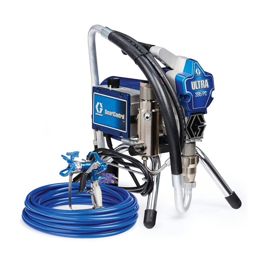
Page 5: Component Identification
Component Identification Component Identification Model 233960 shown English ON/OFF switch Drain tube Siphon tube Pressure control Filter Trigger lock Pump Fluid outlet Prime/Spray valve Service Tag (below sprayer frame) 309665L... -
Page 6: Power Requirements
Component Identification Grounding English The sprayer must be grounded. Grounding reduces the risk of static and electric shock by providing an escape wire for the electrical current due to static build up or in the event of a short circuit. ti2810a •... -
Page 7: Pressure Relief Procedure
Pressure Relief Procedure ti5851a ti5850a Pails • Solvent and oil/based fluids: • Do not place pail on a • Grounding a metal pail: connect a • To maintain grounding follow local code. Use only nonconductive surface such as ground wire to the pail by clamping continuity when flushing or conductive metal pails, placed on paper or cardboard which... - Page 8 Throughout these instructions, Model 233960 is shown in all illustrations. Your sprayer model may look slightly different than pictured. TI2597a ti2769a ti2703a ti2702a Connect Graco airless Connect other end of Tighten securely. Remove tip guard. hose to sprayer. hose to gun.
-
Page 9: Startup
Startup ti2719a WASTE ti2756B FLUSH Turn prime valve down. 10 Place siphon tube set in grounded metal pail partially filled with flushing fluid. Attach ground wire to pail and to true earth ground. Do 1. - 5. of Startup, page 9 to flush out storage oil shipped in sprayer. -
Page 10: Tip And Guard Assembly
Tip and Guard Assembly ti2599a ti2714a ti2713a WASTE WASTE WASTE PAINT Hold gun against grounded Inspect for leaks. Do not stop Place siphon tube in paint pail. metal flushing pail. Trigger leaks with hand or a rag! If leaks Trigger gun again into flushing pail until paint appears. Move gun to gun and increase fluid occur, do Pressure Relief. -
Page 11: Clearing Clog
Tip and Guard Assembly Spraying heavy edges ti2758a ti2757a Spray test pattern. Start with pressure turned to its lowest Hold gun perpendicular, 10-12 in. from surface. Spray back setting, then gradually increase pressure gradually until and forth, overlapping by 50%. To prevent heavy spots, you achieve a consistent spray pattern without heavy before pulling trigger, first move gun using a back and forth edges. - Page 12 Cleanup Cleanup ti2599a ti2719a ti2707a WASTE RESÍDUOS ti2614a À JETER DESECHO ti2769a WASTE WASTE ti2595a Turn power OFF and Turn pressure to lowest Put drain tube in pail. Remove guard and unplug sprayer setting. Trigger gun to Turn prime valve down. SwitchTip.
- Page 13 Ultra/ST Max 395/495/595 Sprayers - Digital Display (Optional) ti2776a Pump Armor ti2814a ti2895a 13 Remove filters from gun 14 If flushing with water, flush again with mineral spirits, or 15 Wipe sprayer, hose and and sprayer, if installed. Pump Armor, to leave a protective coating to prevent gun with a rag soaked in Clean and inspect.
- Page 14 Ultra/ST Max 395/495/595 Sprayers - Digital Display (Optional) ti2827a ti2707a ti2706a Turn power OFF. While pressing display Model number is button, turn power ON to displayed and then Data enter Stored Data mode. Point 1, power on time in hours, is displayed. ti2824a ti2707a Press display button to...
-
Page 15: Ultra Max Ii/St Max Ii Sprayers
Ultra Max II/ST Max II Sprayers Ultra Max II/ST Max II Sprayers ti7484a ti7485a ti7486b Operation Main Menu Short press moves to next display. Follow Pressure Relief, 2 Turn power ON. Pressure display Short press DTS button Press and hold (5 seconds) changes page 7. - Page 16 Ultra Max II/ST Max II Sprayers ti7493a ti7491b Secondary Menu Change Display Units: Press and hold DTS button Press and hold DTS button for to clear error code to zero. Short 8 seconds to change pressure units press to move to software REV. (psi, bar, MPa) to desired units.
- Page 17 Notes Notes 309665L...
-
Page 18: Warranty
With the exception of any special, extended, or limited warranty published by Graco, Graco will, for a period of twelve months from the date of sale, repair or replace any part of the equipment determined by Graco to be defective.
Need help?
Do you have a question about the Ultra 395 and is the answer not in the manual?
Questions and answers