Table of Contents
Advertisement
Repair
®
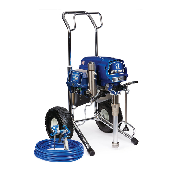
Ultra
Max II/Ultimate Mx II
- For Portable Airless Spraying of Architectural Coatings and Paints. For professional use only.
Not for use in explosive atmospheres.-
3300 psi (22.8 MPa, 227 bar) Maximum Working Pressure
IMPORTANT SAFETY INSTRUCTIONS
Read all warnings and instructions in this
manual. Save these instructions.
See page 3 for model information, including maximum working pressure and approvals.
Korean patent 10-0579681
ti13450a
ti13461a
695/795 HI
MARK V
ti13459a
695/795 LOW
ti13460a
1095/1595 HI
311365H
ENG
Advertisement
Table of Contents


Need help?
Do you have a question about the ultra max ii and is the answer not in the manual?
Questions and answers