Table of Contents
Advertisement
Quick Links
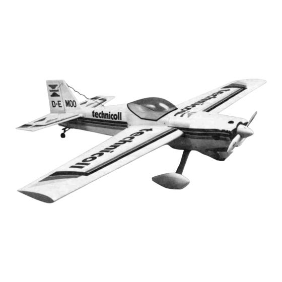
ALMOST READY-TO-FLY RADIO CONTROLLED MODEL AIRPLANE
• SUPERIOR QUALITY IN AN ALMOST-READY-TO-FLY MODEL
• SPECIAL COVERING PROCESS YIELDS A STRONG,
BRILLIANT, AND FUEL-PROOF FINISH
• 90% COMPLETE OUT OF THE BOX—NO SANDING, PAINTING, OR
FINISHING REQUIRED
• SMOOTH, STEADY FLIGHT CHARACTERISTICS, JUST LIKE
A REAL PLANE
• CAPABLE OF FULL 4-CHANNEL AEROBATICS
© ENTIRE CONTENTS COPYRIGHT 1989, HOBBICO, INC.
V1 .0
Advertisement
Table of Contents

Related Manuals for Hobbico Diabolo 40


Summary of Contents for Hobbico Diabolo 40
- Page 1 BRILLIANT, AND FUEL-PROOF FINISH • 90% COMPLETE OUT OF THE BOX—NO SANDING, PAINTING, OR FINISHING REQUIRED • SMOOTH, STEADY FLIGHT CHARACTERISTICS, JUST LIKE A REAL PLANE • CAPABLE OF FULL 4-CHANNEL AEROBATICS © ENTIRE CONTENTS COPYRIGHT 1989, HOBBICO, INC. V1 .0...
-
Page 2: Important: Before You Begin
If the Diabolo 40 is not quite what you expected, return it to your dealer in NEW and UNUSED condition However, we think you will agree with us that the Diabolo 40 is one of the finest models of its type and will offer you... -
Page 3: Parts List
PARTS LIST Before assembly match the parts in the Control Rod (Long) exploded view of the Diabolo with the Main Servo Tray parts in the kit. Check off each part on Stabilizer Supports the parts list. If any parts are missing or Plastic Disc damaged return the kit to your hobby dealer. -
Page 4: Wing Assembly
WING ASSEMBLY (A) Right Wing (Aileron Installed) . . . 1 (I) Wing Mounting Brace ..1 (3) Remove the foam covering from the aileron servo mounting area. Test fit the (B) Left Wing (Aileron Installed) ..1 (J) 4x30mm Bolts . - Page 5 After the joiners have dried, apply epoxy where shown. The wing roots, the Drill two 8mm holes into the wing joiners for the dowel rods. wing joiners and inside the other wing joiner slot should be evenly covered with epoxy. Slide the two wing halves together slowly and wipe off any excess glue.
- Page 6 (12) Epoxy in the main servo tray where shown (15) Screw in the wing bolts half way into the wing bolt mounting block Apply ink or paint to the heads of the two bolts Next center the wing and set it onto the bolts This will mark where you need to drill (13) Test fit the wing bolt mounting block to the inside of the fuselage The blind (16) After the epoxy has cured place the wing into the fuselage as shown Put the...
- Page 7 (21) Epoxy the aileron servo tray mount into the rear section of the wing servo (18) Drill two 4mm holes 90° from the top wing surface for the wing bolts where mount and then epoxy in the tray. the paint marks are. COCKPIT/CANOPY ASSEMBLY (A) Cockpit, .
-
Page 8: Landing Gear Installation
LANDING GEAR INSTALLATION (2) Once the epoxy has cured, position the cockpit on the fuselage Make 4 small (A) Main Gear ..1 (H) Wheel Pants . . .2 (B) Rubber Shock Absorber..1 (1) 4mmx40mm Screw . - Page 9 Now place the main gear (angled side facing back) over the screws and secure Place the 3mm screw/washer into the top hole of the wheel pants from the it with two 4mm nylon nuts NOTE tighten the nuts all the way and then inside And then attach it to the top hole of the main gear using the 3mm nut loosen them both one turn This will give the gear the correct shock absorbing qualities...
-
Page 10: Engine Installation
ENGINE INSTALLATION (A) Engine Mount ....... .1 Hold each mounting plate under one engine mount as shown (Thick side (B) 4mmx20mm Screws . -
Page 11: Fuel Tank Installation
Put the self tapping screw in the center hole from the large end and tighten it Now mount the engine to the fuselage Use (4) 4mmx15mm screws with the only a couple of turns. (4) 4mm washers. Be sure to use screw locking compound on the threads. FUEL TANK INSTALLATION Fuel Tank... -
Page 12: Radio Installation
Attach the complete fuel tank cap to the tank Make sure that the bent pipe is Install the fuel tank from the inside of the fuselage with the fuel lines facing pointing to the top Slide the cap on until the lip on the fuel tank is in the front Slide the tank into its mount and up into the hole in front of the fuselage groove of the cap. - Page 13 Check the fit of your aileron servo in the aileron servo tray You may have to Attach the clevises to the aileron horns and slide on the retaining tubes After trim away some of the servo tray for a good fit Install the grommets onto the checking the neutral position of the aileron servo and ailerons, put a mark on servo and fasten it to the wing using the screws provided with the radio system the push rods where the servo arm holes are...
- Page 14 (10) Install the three remaining servos into the tray using grommets and screws Be Attach the rods to the servo arm using the rod clevis NOTE You may have to sure that the servos are positioned correctly Next mount the radio switch use a different style servo horn for more throw as shown NOTE Make sure that the servo wires all run forward so they are easily accessible...
- Page 15 (16) Assemble the push rod as shown Place the two short (pre bent) rods into one (13) Bend two of the long rods as shown for the elevator and one of the rods for the end of each rod with the single grooves Slide a piece of shrink tubing over rudder each rod and heat with a heat gun or a lighter to shrink the tubing for a tight fit Place the elevator rods into the double grooved end of one of the rods...
- Page 16 (22) Install the plastic tubing through the hole in the firewall to the servo tray Epoxy (19) Use PlastiZap and glue the three plastic push rod exits to the fuselage the tube where it goes in (23) Make a "Z" bend on one end of the throttle control rod and insert the opposite (20) Check to make sure that the rods will easily move in and out with little resistance You may have to bend the rods slightly for a perfect fit (We will end into the tube...
- Page 17 (25) Connect the "Z" bend to the engine throttle arm. It may be necessary to (28) Next, at the marked point, make another "Z" bend, cut off the excess and remove the arm from the engine for easier installation. attach it to the servo arm. For easy adjustments, an easy connect can be used here.
- Page 18 Test fit the 1/8" plywood wedge into the tail end of the fuselage. If there is a Next take a piece of string and attach it with a pin to the top center of the good fit, epoxy it in place making sure that it is even with the fuselage sides. fuselage.
- Page 19 Next, apply epoxy to the top of the horizontal stabilizer and re-position the fin (10) After the glue has completely set, assemble the tail wheel section shown. The between the lines. Make sure that the fin is still 90° to the stabilizer. Do the wheel should be straight in line with the strip as should be the tail control arms.
- Page 20 (13) Attach the two supports onto the fuselage with a 3mmx12mm self tapping (16) Next, drill a 2mm hole about 1" deep at 1 1/8" from the bottom of the screw Make sure that the tail wheel assembly is straight rudder The hole should be straight in from the front edge (17) Notch a small groove (1/8"...
-
Page 21: Control Horn Installation
(19) Carefully position the tail control rod into the hole and the groove. Wipe off any Using PlastiZap again, glue the angled mounting plates, one on each side, on excess epoxy and then insert the hinges into the slots. Wipe off any excess the two elevator halves as shown. - Page 22 Install the six brass tubes into the holes Screw on the plastic snap clevises to the 3 push rods coming out of the fuselage Screw them on half way up the threads Mount the control horns to the surfaces with the 2mmx20mrn screws Pass the Attach the respective control rods to each horn Use the middle hole of the horn Turn on the radio system and adjust the clevises for centered control screws through the horn, next through the tubes and finally thread them into...
- Page 23 Epoxy the small mounting brace to the top of the firewall Fill any gap with (11) Next, make a 90° bend downwards at the mark and cut-off the excess so that epoxy. there is only 5/16" of rod after the bend. Trim away some of the plastic from under the front of the fuselage where (12) Attach the rods to the servos using the rod clevises as shown in the above shown.
- Page 24 Install the muffler onto the engine Trial fit the cowl onto the fuselage so that Drill a 2mm hole at each point and attach the cowl using three 3mmx8mm self the engine crankshaft and drive washer protrude out of the front tapping screws Remove the crankshaft nut and washer and install the spinner back plate onto Trim as needed so that the engine muffler will exit Now make two holes in the...
-
Page 25: Receiver And Battery Installation
Drill a small (1/16") hole into the left side of the fuselage under the wing and (10) Install the spinner with the two 3mmx12mm self tapping screws Attach the drill a hole at the top of the vertical fin cowl decals to each side RECEIVER AND BATTERY INSTALLATION Hook up the servos and wrap the receiver and battery in natural foam rubber to Make a small knot 6"... -
Page 26: Center Of Gravity
SERVO THROWS CENTER OF GRAVITY Balance the plane using the mark on the side of the fuselage It should balance at this The amount of throw that the control surfaces have is critical if you want a properly responsive plane Measure the throws as shown above They should be point See below Each way Total... -
Page 27: Starting Engine
STARTING ENGINE 5. Turn the radio on and open the throttle to full open Place Engine Maintenance your finger over the air intake on the carburetor while turning the prop counter-clockwise a few times Notice the fuel line. Always check the engine mounting bolts, muffler, glow plug, If any fuel is being sucked into the carburetor, turn the prop a propeller and spinner, etc , before attempting to start the engine. -
Page 28: Your First Flight
YOUR FIRST FLIGHT WHERE TO FLY Before starting the engine check and make sure all screws are If you are a novice pilot local area clubs have been formed and tight that the hinges have not come loose, the control surfaces move are very willing to help you with any questions you may have Many in the right directions according to your input on the transmitter, and of the clubs even have club trainer airplanes that they will actually...
Need help?
Do you have a question about the Diabolo 40 and is the answer not in the manual?
Questions and answers