Sign In
Upload
Manuals
Brands
Advantech Manuals
Motherboard
PCM-9581F-S0A1
Advantech PCM-9581F-S0A1 Motherboard Manuals
Manuals and User Guides for Advantech PCM-9581F-S0A1 Motherboard. We have
1
Advantech PCM-9581F-S0A1 Motherboard manual available for free PDF download: User Manual
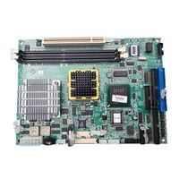
Advantech PCM-9581F-S0A1 User Manual (116 pages)
Intel Pentium M SBC with Audio, VGA, LCD
Brand:
Advantech
| Category:
Motherboard
| Size: 3.56 MB
Table of Contents
Packing List
3
Table of Contents
7
General Information
11
Chapter 1 Introduction
12
Introduction
12
Features
12
Specifications
13
Board Layout: Dimensions
16
Figure 1.2:Board Layout: Dimensions (Solder Side)
17
Chapter 2 Installation
20
Jumpers
20
Jumpers Setting Drawing
20
Connectors
22
Locating Jumpers and Connectors
24
Figure 2.2:Jumper & Connector (Solder Side)
25
Setting Jumpers
26
Clear CMOS (JP3)
27
Installing Dimms
27
IDE, CDROM Hard Drive Connector (CN5, CN6)
28
Connecting the Hard Drive
28
Solid State Disk
28
Compactflash (CN20)
28
Floppy Drive Connector (CN8)
29
Connecting the Floppy Drive
29
Parallel Port Connector (CN4)
30
Keyboard and PS/2 Mouse Connector (CN19)
30
Front Panel Connector (CN3)
30
Power & HDD LED (Pin 1-4 of CN3)
30
Reset Switch (Pin 13-14 of CN3)
30
Power Connectors (CN10,CN15)
31
ATX Power Connector, +5V (CN15)
31
CPU Fan Power Supply Connector (CN10)
31
ATX Power ON/OFF Switch Con. Pin 11-12 of CN3
31
ATX Feature (CN15) & Soft Power Switch (CN3)
31
Audio AC'97 Link Interfaces (CN14)
31
Audio Connector(CN14)
31
CD Audio-In Connector (CN18)
32
COM Port Connector (CN11)
32
VGA/LVDS Interface Connections (CN13, CN16,CN7)
32
CRT Display Connector (CN13)
32
LVDS LCD Panel Connector (CN16)
32
DVI LCD Panel Connector(CN7)
33
TV-Out Interface (CN12)
33
Ethernet Configuration (CN2, CN23)
33
100Base-T Connector (CN23, PCM-9581F)
33
1000Base-T Connector (CN2, PCM-9581FG)
34
Network Boot
34
USB Connectors (CN25,CN26,CN27)
34
Chapter 3 Software Configuration
36
Introduction
36
Connections to Three Standard Lcds
37
LG LM150X06 (1024X768(16 Colors) LVDS LCD)
37
Chapter 4 Award BIOS Setup
40
System Test and Initialization
40
System Configuration Verification
40
Award BIOS Setup
41
Entering Setup
41
Standard CMOS Features Setup
42
Advanced BIOS Features Setup
43
Advanced Chipset Features Setup
44
Integrated Peripherals
44
Power Management Setup
45
Pnp/Pci Configurations
45
PC Health Status
46
Frequency/Voltage Control
47
Load Optimized Defaults
48
Set Password
48
Save & Exit Setup
49
Exit Without Saving
49
Chapter 5 PCI Graphic Setup
52
Introduction
52
Chipset
52
PCM-9581 User's Manual
52
Display Memory
52
Display Types
52
Dual/Simultaneous Display
53
Figure 5.1:Selecting Display Settings
54
Installation of the PCI Graphic Driver
55
Installation for Windows 98/ME/2000/XP
55
Further Information
57
Chapter 6 Audio Setup
60
Introduction
60
Driver Installation
60
Before You Begin
60
Lan Configuration
65
Chapter 7 PCI Bus Ethernet Interface
66
Introduction
66
Features
66
Installation of Ethernet Driver
66
Installation for Windows 2000
67
Installation for Windows NT
71
Further Information
77
Appendix A Prog. GPIO & W'dog Timer
80
Supported GPIO Register
80
GPIO Registers
80
GPIO Example Program-1
81
Watchdog Programming
83
A.2 Watchdog Programming
83
Pin Assignments
85
Appendix B Pin Assignments
86
CPU Fan Connector (CN10)
86
Ethernet 10/100Base-T Connector (CN23)
87
Ethernet 10/100/1000 BASE-T Connector (CN2)
88
Ethernet LED Connector(CN1)
89
Aclink Audio Connector (CN14)
89
CD-IN Connector (CN18)
90
ATX Main Power Connector (CN15)
90
B.6 CD-IN Connector (CN18)
90
Keyboard and PS/2 Mouse Connector (CN19)
91
Floppy Disk Drive Connector (CN8)
92
IDE Hard Drive Connector (CN5, CN6)
93
Parallel Port Connector (CN4)
94
Front Panel LED (CN3)
95
USB Connector (CN25,26,27)
96
SIR Connector (CN24)
96
TV out Connector (CN12)
97
LCD Inverter Backlight Connector (CN17)
98
CRT Display Connector (CN13)
98
LVDS Connector (CN16)
99
COM Port Connector (CN11)
100
Compactflash Card Connector (CN20)
101
GPIO Connector (CN9)
102
TMDS Connector(CN7)
103
B.22 TMDS Connector(CN7)
103
Mini PCI Connector
104
Appendix C System Assignments
106
System I/O Ports
106
1St MB Memory Map
107
DMA Channel Assignments
107
Interrupt Assignments
108
C.4 Interrupt Assignments
108
Appendix D Optional Extras
110
PCM-10586-6100 Cable Kit for PCM-9581F
110
PCM-10586-6A00 Cable Kit for PCM-9581FG
111
Optional USB Cable (CN25,26,27)
112
ATX Power Control Cable (CN15)
112
D.3 Optional USB Cable (CN25,26,27)
112
Mechanical Drawings
113
Appendix E Mechanical Drawings
114
Advertisement
Advertisement
Related Products
Advantech PCM-9588
Advantech INTEL PCM-9587
Advantech PCM-9581
Advantech PCM-9581F-00A1
Advantech PCM-9581FG-00A1
Advantech PCM-9581FG-S0A1
Advantech PCM-9586
Advantech PCM-9590
Advantech PCM-9576F
Advantech PCM-9575F-J0A1
Advantech Categories
Motherboard
Computer Hardware
Desktop
Network Router
Touch Panel
More Advantech Manuals
Login
Sign In
OR
Sign in with Facebook
Sign in with Google
Upload manual
Upload from disk
Upload from URL