Table of Contents
Advertisement
Quick Links
Advertisement
Table of Contents

Related Manuals for Perkins 35943


Summary of Contents for Perkins 35943
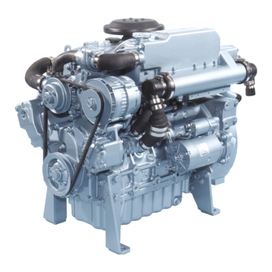
- Page 1 Part No 35943 ® User’s Handbook 700GM...
- Page 3 © Proprietary information of Wimborne Marine Power Centre, all rights reserved. The information is correct at the time of print. Published in December 2013 by Wimborne Marine Power Centre, Wimborne Marine Power Centre, Wimborne, Dorset, England BH21 7PW Tel:+44(0)1202 796000 Fax: +44(0)1202 796001 E-mail: Marine@Perkins.com www.perkins.com/marine...
- Page 4 Title 35943...
-
Page 5: Table Of Contents
35943 Table of Contents Page General information Introduction ........................1 How to care for your engine .....................2 General safety precautions....................3 Engine guarantee ......................4 Engine identification ......................4 Engine views Introduction ........................7 Location of engine parts ....................8 Front and left side view (A) ...................8 Rear and right side view (B) ..................9... - Page 6 Table of Contents 35943 How to renew the canister of the lubricating oil filter .............25 How to renew the engine breather assembly ..............26 How to renew the element of the air filter ...............27 How to set the valve tip clearances ................28 Seacock strainer ......................29...
-
Page 7: General Information
Perkins Engines Ltd and Wimborne Marine Power Centre. Wimborne Marine Power Centre are the managers of the Perkins marine business and all enquires should be made to Wimborne Marine Power Centre; refer to the company address list on page 5. -
Page 8: How To Care For Your Engine
Renew the filter canister and lubricating oil regularly in order to ensure that the inside of your engine remains clean. Ensure that all adjustments and repairs are done by personnel who have had the correct training. Perkins distributors have this type of personnel available. You can also obtain parts and service from your Perkins distributor. -
Page 9: General Safety Precautions
• The latest marine engines have a cover fitted to give some protection from the alternator fan and the drive belt. Ensure that this cover is fitted before the engine is started. • Fit only genuine Perkins parts. Page 3... -
Page 10: Engine Guarantee
35943 Engine guarantee If a claim under guarantee is necessary, the owner should make a guarantee claim on the nearest Perkins marine distributor or an approved dealer. If it is difficult to find a Perkins distributor or an approved dealer, consult the Service Department of Wimborne Marine Power Centre, refer to the company address list on page 5. -
Page 11: Perkins Main Dealers
Telephone: 0040 (0) 1202 796000 Telephone: [81] (3) 5157 0571 Fax: 0040 (0) 1202 796001 Fax: Fax: [81] (3) 5157 0572 www.perkins.com/marine. *This is just a small selection of Perkins dealers. For a more comprehensive list, please see www.perkins.com/marine. Page 5... - Page 12 Chapter 1 35943 Page 6...
-
Page 13: Engine Views
35943 Chapter 2 Engine views Introduction Perkins engines are built for specific applications and the views which follow do not necessarily match your engine specification. Page 7... -
Page 14: Location Of Engine Parts
Chapter 2 35943 Location of engine parts Front and left side view (A) 1. Coolant header tank / cooled exhaust manifold 2. Heat exchanger 3. Connection for the raw water inlet 4. Starter motor 5. Strainer 6. Sump drain plug 7. -
Page 15: Rear And Right Side View (B)
35943 Chapter 2 Rear and right side view (B) 15. Filler cap for coolant circuit 16. Air filter 17. Atomiser 18. Fuel injection pump 19. Electric actuator 20. Fuel lift pump 21. Lubricating oil dipstick 22. Canister for the fuel filter 23. - Page 16 Chapter 2 35943 Page 10...
-
Page 17: Operation Instructions
35943 Chapter 3 Operation instructions How to start the engine Several factors affect engine start, for example: • The power of the battery • The performance of the starter motor • The viscosity of the lubricating oil • The installation of a cold start system •... -
Page 18: How To Stop The Engine
The idle or the maximum speed settings must not be changed by the engine operator, because this can damage the engine or generator. The warranty of the engine can be affected if the seals on the fuel injection pump are broken during the warranty period by a person who is not approved by Perkins. Running-in A gradual running-in of a new engine is not necessary. -
Page 19: Preventive Maintenance
35943 Chapter 4 Preventive maintenance Preventive maintenance periods These preventive maintenance periods apply to average conditions of operation. Check the periods given by the manufacturer of the boat in which the engine is installed. If necessary, use the shorter periods. When the operation of the engine must conform to the local regulations these periods and procedures may need to be adapted to ensure correct operation of the engine. -
Page 20: Schedules
Chapter 4 35943 Schedules The schedules which follow must be applied at the interval (hours or months) which occur first. First service at 25/50 hours Every 1000 hours Every day or every 8 hours Every 2000 hours Every 500 hours or 12 months F... -
Page 21: How To Drain The Coolant Circuit
35943 Chapter 4 How to drain the coolant circuit Warnings! • Do not drain the coolant while the engine is still hot and the system is under pressure because dangerous hot coolant can be discharged. • Discard used coolant in a safe place and in accordance with local regulations. -
Page 22: How To Check The Specific Gravity Of The Coolant
Chapter 4 35943 How to check the specific gravity of the coolant For mixtures which contain inhibited ethylene glycol: 1. Operate the engine until it is warm enough to open the thermostat. Continue to run the engine until the coolant has circulated through the cooling system. -
Page 23: How To Drain The Raw Water System
35943 Chapter 4 How to drain the raw water system Caution:The raw water system cannot be drained completely. If the system is drained for engine preservation purposes or for protection from frost, the system must be filled again with an approved coolant mixture. -
Page 24: How To Clean The Strainer For The Raw Water Pump
Chapter 4 35943 How to clean the strainer for the raw water pump The strainer for the raw water pump is fitted in the outlet hose for the raw water pump. The purpose of the strainer is to protect the engine heat exchanger from debris. -
Page 25: How To Check The Impeller Of The Raw Water Pump
35943 Chapter 4 How to check the impeller of the raw water pump 1. Ensure that the seacock is closed. 2. Release the six setscrews (A1 page 17) which fasten the end plate of the raw water pump and remove the plate. -
Page 26: How To Check The Drive Belt
How to adjust the belt tension Cautions: • The alternator is driven by a drive belt of a specific design. Use only a Perkins POWERPART drive belt. If this is not done, an early failure of the belt may occur. -
Page 27: How To Renew The Element Of The Fuel Filter
Warning! Discard the used element and fuel in a safe place and in accordance with local regulations. Caution: It is important that only the genuine Perkins parts are used. The use of wrong parts could damage the fuel injection equipment. -
Page 28: How To Renew An Atomiser
Chapter 4 35943 How to renew an atomiser Cautions: • A new clamp (A5) must be used every time an atomiser is fitted to the engine. • Do not allow dirt to enter the fuel system. Before a connection is disconnected, clean thoroughly the area around the connection. -
Page 29: How To Eliminate Air From The Fuel System
35943 Chapter 4 How to eliminate air from the fuel system Caution: When air is to be eliminated from the fuel system, only use the starter motor to start the engine after air has been eliminated from the low-pressure side of the fuel system. -
Page 30: How To Renew The Lubricating Oil
Chapter 4 35943 How to renew the lubricating oil Warning! Discard the used lubricating oil in a safe place and in accordance with local regulations. Note: Renew the filter canister when the lubricating oil is renewed. 1. Connect a suitable hose to the outlet of the sump drain pump (A1). -
Page 31: How To Renew The Canister Of The Lubricating Oil Filter
• Do not fill the sump past the notch (B2 page 24) on the dipstick. • The canister contains a valve and special tube to ensure that lubricating oil does not drain from the filter. Therefore, ensure that the correct Perkins POWERPART canister is used. Page 25... -
Page 32: How To Renew The Engine Breather Assembly
Chapter 4 35943 How to renew the engine breather assembly Cautions: • It is important that the area around the vent hole (A3) is kept clean and the vent hole is not restricted. • Ensure that the pipe (A1) does not contact other components as this may cause the failure of the pipe. -
Page 33: How To Renew The Element Of The Air Filter
35943 Chapter 4 How to renew the element of the air filter 1. Release the hose clip (A1) and remove the air filter assembly. 2. Remove the filter element (B2) from inside the filter assembly (B1). 3. Fit a new filter element and fit the filter assembly to the engine. -
Page 34: How To Set The Valve Tip Clearances
Chapter 4 35943 How to set the valve tip clearances Notes: • The valve tip clearance is checked with a feeler gauge between the top of the valve stem and the rocker lever (A), with the engine cold. The correct clearance for both the inlet and the exhaust valves is 0,35 mm (0.014 in). -
Page 35: Seacock Strainer
Specialist manufacturers will advise on the maintenance of these anodes. Supplementary tools A general tool kit and an on-board spares kit are available from your Perkins Distributor. It is recommended that the tools and other parts, listed below, are also retained on-board:... - Page 36 Chapter 4 35943 Page 30...
-
Page 37: Engine Fluids
If you need advice on adjustments to an engine setting or to the lubricating oil change periods which may be necessary because of the standard of the available fuel, consult your nearest Perkins distributor or Wimborne Marine Power Centre, see page 5. -
Page 38: Lubricating Oil Specification
Chapter 5 35943 Lubricating oil specification Use only a good quality lubricating oil that is not less than the specification API CC or ACEA E1. API CD or ACEA E2 can be used, but is not recommended during the first 25 to 50 hours nor for light load applications. -
Page 39: Coolant Specification
35943 Chapter 5 Coolant specification The quality of the coolant which is used can have a great effect on the efficiency and life of the cooling system. The recommendations indicated below can help to maintain a good cooling system and to protect it against frost and/or corrosion. - Page 40 Chapter 5 35943 Page 34...
-
Page 41: Fault Diagnosis
35943 Chapter 6 Fault diagnosis Problems and possible causes Engine problem Possible causes Checks by the user Checks by the workshop personnel The starter motor turns the engine too slowly 1, 2, 3, 4 The engine does not start 5, 6, 7, 8, 9, 10, 12, 13, 14,... -
Page 42: List Of Possible Causes
Chapter 6 35943 List of possible causes 37. Valve timing is incorrect. 38. Bad compression. 1. Battery capacity low. 39. Cylinder head gasket leaks. 2. Bad electrical connections. 40. Valves are not free. 3. Fault in starter motor. 41. Wrong high-pressure pipes fitted. -
Page 43: Engine Preservation
35943 Chapter 7 Engine preservation Introduction The recommendations indicated below are designed to prevent damage to the engine when it is withdrawn from service for a prolonged period. Use these procedures after the engine is withdrawn from service. The instructions for the use of POWERPART products are given on the outside of each container. -
Page 44: How To Add Coolant To The Raw Water System For Engine Preservation Purposes
Connect the stop solenoid. 18. If the engine protection is done correctly according to the above recommendations, no corrosion damage will normally occur. Perkins are not responsible for damage which may occur when an engine is in storage after a period in service. -
Page 45: Powerpart Recommended Consumable Products
Chapter 8 POWERPART recommended consumable products Perkins have made available the products recommended below in order to assist in the correct operation, service and maintenance of your engine and your machine. The instructions for the use of each product are given on the outside of each container. -
Page 46: Powerpart Safety Cleaner
Chapter 8 35943 POWERPART Safety cleaner General cleaner in an aerosol container. Part number 21820128. POWERPART Silicone adhesive An RTV silicone adhesive for application where low pressure tests occur before the adhesive sets. Used for sealing flange where oil resistance is needed and movement of the joint occurs. Part number 21826038. -
Page 47: General Data
35943 Chapter 9 General data Engine Number of cylinders............................4 Cylinder arrangement ..........................In line Cycle............................... Four stroke Induction system:........................ Naturally aspirated Combustion system ........................Direct injection Nominal bore ........................97,0 mm (3.82 in) Stroke ..........................100,0 mm (3.94 in) Compression ratio ..........................17.5:1 Cubic capacity ........................2,9 litres (183 in 3 ) - Page 48 Chapter 9 35943 Page 42...
- Page 49 California Proposition 65 Warning Diesel engine exhaust and some of its constituents are known to the State of California to cause cancer, birth defects, and other reproductive harm.
- Page 50 All information in this document is substantially correct at time of printing and may be altered Wimborne Marine Power Centre subsequently. 22 Cobham Road, Part No. 35943 issue 5 Ferndown Industrial Estate, Produced in England ©2013 by Wimborne Wimborne, Dorset, BH21 7PW, England. Marine Power Centre...
Need help?
Do you have a question about the 35943 and is the answer not in the manual?
Questions and answers