
Related Manuals for Perkins 1104D-E44T


Summary of Contents for Perkins 1104D-E44T
-
Page 1: Operation And Maintenance
SEBU9066 March 2014 Operation and Maintenance Manual 1104D-E44T and 1104D-E44TA Industrial Engines NP (Engine) NR (Engine) -
Page 2: Important Safety Information
These changes can affect the service that is given to the product. Obtain the complete and most current information before you start any job. Perkins dealers or Perkins distributors have the most current information available. When replacement parts are required for this product Perkins recommends using Perkins replacement parts. -
Page 3: Table Of Contents
SEBU9066 Table of Contents Table of Contents Maintenance Section Refill Capacities..........54 Foreword............4 Maintenance Recommendations....67 Safety Section Maintenance Interval Schedule ...... 69 Safety Messages..........5 Warranty Section General Hazard Information ......7 Warranty Information .... -
Page 4: Foreword
Operation and Maintenance Manual except for the Operation interval and the maintenance items in that interval. Major repairs should only be carried out by Perkins Operating techniques outlined in this manual are authorized personnel. Your Perkins dealer or your basic. They assist with developing the skills and... -
Page 5: Safety Section
If a warning sign is attached to a part of the engine that is replaced, install a new warning sign on the replacement part. Your Perkins dealer or your Perkins distributor can provide new warning signs. (1) Universal Warning... -
Page 6: Hand (High Pressure)
SEBU9066 Safety Section Safety Messages Illustration 2 g03450122 2 Hand (High Pressure) Contact with high pressure fuel may cause fluid penetration and burn hazards. High pressure fuel spray may cause a fire hazard. Failure to follow these inspection, maintenance and service in- structions may cause personal injury or death. -
Page 7: General Hazard Information
SEBU9066 Safety Section General Hazard Information Illustration 5 g01154809 Illustration 7 g00702020 Typical example Wear a hard hat, protective glasses, and other protective equipment, as required. The ether warning label is supplied loose for the original equipment manufacture to install the label. Do not wear loose clothing or jewelry that can snag on controls or on other parts of the engine. -
Page 8: Burn Prevention
SEBU9066 Safety Section Burn Prevention Static Electricity Hazard when The maximum air pressure for cleaning purposes must be below 205 kPa (30 psi). The maximum water Fueling with Ultra-low Sulfur Diesel pressure for cleaning purposes must be below Fuel 275 kPa (40 psi). Fluid Penetration The removal of sulfur and other compounds in ultra- low sulfur diesel fuel (ULSD fuel) decreases the... -
Page 9: Fire Prevention And Explosion Prevention
Do not allow electrolyte to contact the skin or If the application involves the presence of the eyes. Always wear protective glasses for combustible gases, consult your Perkins dealer and/ servicing batteries. Wash hands after touching the or your Perkins distributor for additional information batteries and connectors. - Page 10 SEBU9066 Safety Section Fire Prevention and Explosion Prevention Do not weld on lines or tanks that contain flammable fluids. Do not flame cut lines or tanks that contain flammable fluid. Clean any such lines or tanks thoroughly with a nonflammable solvent prior to welding or flame cutting.
-
Page 11: Crushing Prevention And Cutting Prevention
Do not install any lines that are damaged. Do not climb on the engine. The engine has not been Leaks can cause fires. Consult your Perkins dealer or designed with mounting or dismounting locations. your Perkins distributor for replacement parts. - Page 12 SEBU9066 Safety Section High Pressure Fuel Lines Illustration 12 g03452057 (1) High-pressure line (4) High-pressure line (7) High-pressure supply line (2) High-pressure line (5) High-pressure fuel manifold (rail) (3) High-pressure line (6) High-pressure supply line The high-pressure fuel lines are the fuel lines that are Do not loosen the high-pressure fuel lines in order to between the high-pressure fuel pump and the high- remove air from the fuel system.
-
Page 13: Before Starting Engine
SEBU9066 Safety Section Before Starting Engine • Inspect the high-pressure fuel lines for damage, All protective guards and all protective covers must be installed if the engine must be started in order to deformation, a nick, a cut, a crease, or a dent. perform service procedures. -
Page 14: Engine Stopping
SEBU9066 Safety Section Engine Stopping Grounding Practices Note: The engine is equipped with a device for cold starting. If the engine will be operated in very cold conditions, then an extra cold starting aid may be required. Normally, the engine will be equipped with the correct type of starting aid for your region of operation. -
Page 15: Engine Electronics
Note: Many of the engine control systems and The power supply connections and the ground display modules that are available for Perkins connections for the engine electronics should always Engines will work in unison with the Engine be from the isolator to the battery. -
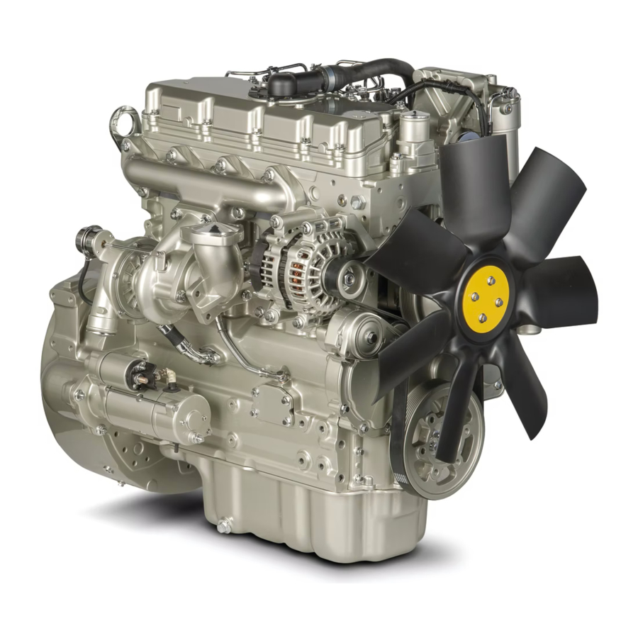
Page 16: Product Information Section
SEBU9066 Product Information Section Model View Illustrations Product Information Section General Information i05536748 Model View Illustrations The following model views show typical features of the engine Due to individual applications, your engine may appear different from the illustrations. Turbocharged Aftercooled Engine Illustration 15 g03453518 Typical example... - Page 17 SEBU9066 General Information Model View Illustrations Illustration 16 g03453526 Typical example (9) Front Lifting Eye (11) Coolant Intake (13) Belt (10) Water Pump (12) Tensioner (14) Coolant Outlet...
- Page 18 SEBU9066 General Information Model View Illustrations Illustration 17 g03453529 Typical example (15) Rear Lifting Eye (18) Starter Solenoid (21) Flywheel (16) Alternator (19) Starting Motor (22) Flywheel Housing (17) Turbocharger (20) Oil Drain Plug (23) Coolant Drain Plug...
- Page 19 SEBU9066 General Information Model View Illustrations Turbocharge Engine View Illustration 18 g03506649 Typical example...
-
Page 20: Product Description
(27) Primary Fuel Filter Note: Item (28) is part of the filtered breather system. i05536753 Product Description There are two different variants of this Perkins engine. Engines with prefix NR are turbocharged aftercooled engines 1104D-E44TA. Engines with prefix NP are turbocharged engines 1104D-E44T. -
Page 21: Engine Cooling And Lubrication
SEBU9066 General Information Product Description Engine Diagnostics Table 1 Engine Specifications The engine has built-in diagnostics in order to ensure that the engine systems are functioning correctly. The Operating Range (rpm) 900 to 2800 operator will be alerted to the condition by a “Stop or Number of Cylinders Warning”... -
Page 22: Product Identification Information
Plate Locations and Film Locations Illustration 22 g02433756 Typical example Illustration 21 g03453612 Perkins engines are identified by an engine serial number. An example of an engine number is N- *****R000001X. ***** The list number for the engine Type of engine... -
Page 23: Emissions Certification Film
SEBU9066 Product Identification Information Emissions Certification Film i05536952 Emissions Certification Film Illustration 23 g03506769 Typical example (If equipped) Filtered Breather i05465764 Reference Information Information for the following items may be needed to order parts. Locate the information for your engine. Record the information in the appropriate space. -
Page 24: Operation Section
The engine must be stored in a water proof building. The building must be kept at a constant temperature. Engines that are filled with Perkins ELC will have coolant protection to an ambient temperature of −36° C (−32.8° F). The engine must not be subjected to extreme variations in temperature and humidity. -
Page 25: Open Cooling System
SEBU9066 Lifting and Storage Product Storage Sealed Coolant System Ensure that the cooling system is filled with Perkins ELC, or an antifreeze that meets “ASTM D6210” specification. Open Cooling System Ensure that all cooling drain plugs have been opened. Allow the coolant to drain. Install the drain plugs. -
Page 26: Features And Controls
SEBU9066 Features and Controls Alarms and Shutoffs Features and Controls Intake manifold air temperature – The intake manifold air temperature sensor indicates high intake air temperature. i05251301 Intake manifold pressure – The intake manifold Alarms and Shutoffs pressure sensor checks the rated pressure in the engine manifold. -
Page 27: Gauges And Indicators
Determine and correct the cause of any significant procedure: change in the readings. Consult your Perkins dealer or your distributor Perkins for assistance. 1. Reduce the load and the engine rpm. Some engine applications are equipped with Indicator 2. -
Page 28: Instrument Panels And Displays
SEBU9066 Features and Controls Gauges and Indicators • Shutdown Lamp • Warning Lamp • Wait to Start Lamp • Low Oil Pressure Lamp For information, refer to this manual, “Monitoring System (Table for the Indicator Lamps)” for the sequence of operation of the shutdown lamp and the warning lamp. -
Page 29: Monitoring System
SEBU9066 Features and Controls Monitoring System i02330192 Monitoring System Table 2 Shutdown Warning Lamp Lamp Status Description of lamp status Engine Status Lamp Lamp check When the engine start switch is turned to the “ON” po- The engine has not been sition both lamps will illuminate for 2 seconds only. -
Page 30: Sensors And Electrical Components
For each of the programmed modes, refer to Troubleshooting Guide, “Indicator Lamps” for more information on Indicator Lamps. For more information or assistance for repairs, consult your Perkins dealer or your Perkins distributor. i05251914 Overspeed An overspeed condition is detected by the Electronic Control Module (ECM). - Page 31 SEBU9066 Features and Controls Sensors and Electrical Components Illustration 25 g03470316 Typical example (1) Coolant Temperature Sensor (4) Connector for Injectors 1 and Injector 2 (7) Fuel Rail Pressure Sensor (2) Inlet Manifold Pressure Sensor (5) Connector for Injectors 3 and Injector 4 (8) Diagnostic Connector (3) Bus Bar for Glow Plugs (6) Inlet Manifold Temperature Sensor...
- Page 32 SEBU9066 Features and Controls Sensors and Electrical Components Illustration 26 g03470317 Typical example (9) Electronic Control Module (11) Oil Pressure Sensor (13) Solenoid for the high-pressure fuel (10) Primary Speed/Timing sensor (12) Secondary Speed/Timing sensor pump...
- Page 33 SEBU9066 Features and Controls Sensors and Electrical Components Illustration 27 g03470356 Typical example (14) Alternator (16) Water in Fuel Switch (15) Starting Motor and solenoid (17) Electric Fuel Pump/Priming Pump...
- Page 34 SEBU9066 Features and Controls Sensors and Electrical Components Illustration 28 g03471916 Typical example (1) Coolant Temperature Sensor (3) Bus Bar for Glow Plugs (5) Connector for Injectors 3 and Injector 4 (2) Inlet Manifold Pressure Sensor (4) Connector for Injectors 1 and Injector 2 (6) Inlet Manifold Temperature Sensor...
- Page 35 SEBU9066 Features and Controls Sensors and Electrical Components Illustration 29 g03471957 Typical example (7) Fuel Rail Pressure Sensor (10) Primary Speed/Timing sensor (13) Solenoid for the high-pressure fuel (8) Diagnostic Connector (11) Oil Pressure Sensor pump (9) Electronic Control Module (12) Secondary Speed/Timing sensor...
- Page 36 SEBU9066 Features and Controls Sensors and Electrical Components Illustration 30 g03474458 Typical example (14) Alternator (16) Water in Fuel Switch (15) Starting Motor and solenoid (17) Electric Fuel Pump/Priming Pump...
-
Page 37: Engine Diagnostics
Retrieval Self-Diagnostics “ “ Diagnostic” ” Lamp Perkins electronic engines have the capability to perform a self-diagnostics test. When the system Use the “DIAGNOSTIC” lamp or an electronic detects an active problem, a diagnostic lamp is service tool to determine the diagnostic flash code. - Page 38 SEBU9066 Engine Diagnostics Diagnostic Flash Code Retrieval Table 3 Flash Codes for the Industrial Engine Diagnostic Effect On Engine Performance Suggested Operator Action Flash Code Description Engine Low Power Reduced Engine Service Schedule a Misfire Engine Shutdown Service. Speed No. 1 Injector Fault No.
-
Page 39: Fault Logging
SEBU9066 Engine Diagnostics Fault Logging (Table 3, contd) Engine Fuel Supply Pump Relay Software Mismatch Machine Security Module Ignition Key Switch Fault ECM Power Supply Voltage Fault SAE J1939 Data Link Fault 5 Volt Sensor DC Power Supply Fault 8 Volt Sensor DC Power Supply Fault Customer/System Parmeter Fault... -
Page 40: Configuration Parameters
SEBU9066 Engine Diagnostics Engine Operation with Intermittent Diagnostic Codes i01902995 Engine Operation with Intermittent Diagnostic Codes If a diagnostic lamp illuminates during normal engine operation and the diagnostic lamp shuts off, an intermittent fault may have occurred. If a fault has occurred, the fault will be logged into the memory of the Electronic Control Module (ECM). -
Page 41: Customer Specified Parameters
SEBU9066 Engine Diagnostics Configuration Parameters Table 4 System Configuration Parameters Configuration Parameters Record Engine Serial Number Rating Full Load Setting Full Torque Setting ECM Software Release Date Customer Specified Parameters Customer specified parameters allow the engine to be configured to the exact needs of the application. The electronic service tool is required in order to alter the customer configuration parameters. - Page 42 SEBU9066 Engine Diagnostics Configuration Parameters (Table 5, contd) PTO Mode Throttle Lock Engine Set Speed 1 Throttle Lock Engine Set Speed 2 Throttle Lock Increment Speed Ramp Rate Throttle Lock Decrement Speed Ramp Rate Throttle Lock Engine Set Speed Increment Throttle Lock Engine Set Speed Decrement Miscellaneous Monitoring Mode Shutdowns...
- Page 43 SEBU9066 Engine Diagnostics Configuration Parameters (Table 5, contd) Minimum Air Flow Coolant Temperature Transmission Oil Temperature Input Enable Status Hydraulic Oil Temperature Input Enable Status Auxiliary #1 Temperature Input Enable Status Auxiliary #2 Temperature Input Enable Status Configurable Inputs Coolant Level Sensor Air Filter Restriction Switch Installation Status Air Filter Restriction Switch Configuration Water in Fuel Switch Installation Status...
-
Page 44: Engine Starting
SEBU9066 Engine Starting Before Starting Engine Engine Starting i05570730 Cold Weather Starting i02837427 Before Starting Engine Perform the required daily maintenance and other Do not use aerosol types of starting aids such as periodic maintenance before the engine is started. ether. -
Page 45: Starting The Engine
SEBU9066 Engine Starting Starting the Engine 5. Repeat step 2 through step 4 if the engine fails to NOTICE start. Do not engage the starting motor when flywheel is turning. Do not start the engine under load. Note: After starting, the engine may be held at low If the engine fails to start within 30 seconds, release speed for a duration between 1 and 25 seconds to the starter switch or button and wait two minutes to al-... -
Page 46: After Starting Engine
SEBU9066 Engine Starting After Starting Engine i05495593 NOTICE Using a battery source with the same voltage as the After Starting Engine electric starting motor. Use ONLY equal voltage for jump starting. The use of higher voltage will damage the electrical system. After starting, the engine may be held at low speed Do not reverse the battery cables. -
Page 47: Engine Operation
Fuel Conservation Practices The efficiency of the engine can affect the fuel economy. Perkins design and technology in manufacturing provides maximum fuel efficiency in all applications. Follow the recommended procedures in order to attain optimum performance for the life of the engine. -
Page 48: Cold Weather Operation
• The cooling system and the lubrication system for Perkins Diesel Engines can operate effectively in cold the engine do not lose heat immediately upon weather. During cold weather, the starting and the shutdown. -
Page 49: Viscosity Of The Engine Lubrication Oil
For this reason, when the engine is started, the 240 V dc. The output can be 750/1000W. Consult engine must be operated until the coolant your Perkins dealer or your Perkins distributor for temperature is 80° C (176° F) minimum. Carbon more information. -
Page 50: Fuel Related Components In Cold Weather
The coolant then returns to the cylinder Note: Only use grades of fuel that are recommended block via an internal passage that bypasses the valve by Perkins. Refer to this Operation and Maintenance of the coolant temperature regulator. This return Manual, “Fluid Recommendations”. -
Page 51: Fuel Filters
SEBU9066 Cold Weather Operation Fuel Related Components in Cold Weather Some fuel tanks use supply pipes that allow water and sediment to settle below the end of the fuel supply pipe. Some fuel tanks use supply lines that take fuel directly from the bottom of the tank. -
Page 52: Engine Stopping
SEBU9066 Engine Stopping Stopping the Engine Engine Stopping Emergency Stop Button i05538749 Stopping the Engine NOTICE Stopping the engine immediately after it has been working under load, can result in overheating and ac- celerated wear of the engine components. Avoid accelerating the engine prior to shutting it down. - Page 53 SEBU9066 Engine Stopping After Stopping Engine • After the engine has stopped, wait for 60 seconds in order to allow the fuel pressure to be purged from the high-pressure fuel lines before any service or repair is performed on the engine fuel lines.
-
Page 54: Maintenance Section
SEBU9066 Maintenance Section Refill Capacities Maintenance Section NOTICE If the engine is to be stored in, or shipped to an area with below freezing temperatures, the cooling system Refill Capacities must be either protected to the lowest outside temper- ature or drained completely to prevent damage. i05502490 NOTICE Refill Capacities... -
Page 55: Coolant Recommendations
• Plugging of radiators, coolers, and small passages • ASTM American Society for Testing and Materials Glycol The following two coolants are used in Perkins Glycol in the coolant helps to provide protection diesel engines: against the following conditions: Preferred – Perkins ELC Acceptable –... -
Page 56: Elc Cooling System Maintenance
3000 Service Hours or One Year (SCA). Water Use the interval that occurs first. The cooling system must also When using Perkins ELC, do not use standard SCA's be flushed out at this time. or SCA filters. ELC Cooling System Cleaning... - Page 57 As needed, add the is completely clean. coolant mixture in order to fill the system to the specified level. 9. Fill the cooling system with the Perkins Premixed ELC. Changing to Perkins ELC ELC Cooling System Contamination...
-
Page 58: Engine Oil Specification
X is the amount of SCA that is required. hydrometer should not be used. Perkins engine cooling systems should be tested at Table 15 is an example for using the equation that is 500 hour intervals for the concentration of SCA. -
Page 59: Engine Oil
“SAE J754”. Some classifications follow “SAE J183” abbreviations, and some classifications follow the “EMA Recommended Guideline on Diesel Engine Oil”. In addition to Perkins definitions, there are other definitions that will be of assistance in purchasing lubricants. Recommended oil viscosities can be found in this publication, “Fluid Recommendations/... -
Page 60: Fuel Specification
• The Oil Condition Analysis determines the loss of the oils lubricating properties. An infrared analysis Perkins does not recommend the use of aftermarket additives in oil. It is not necessary to use aftermarket is used to compare the properties of new oil to the additives in order to achieve the engines maximum properties of the used oil sample. -
Page 61: Diesel Fuel Requirements
Contact your local Perkins distributor for the most up-to-date recommendations. Diesel Fuel Requirements Perkins is not in a position to continuously evaluate and monitor all worldwide distillate diesel fuel specifications that are published by governments and technological societies. - Page 62 Regional regulations, national regulations, or international regulations can require a fuel with a specific sulfur limit. Consult all applicable regu- lations before selecting a fuel for a given engine application. Perkins fuel systems and engine components can operate on high sulphur fuels.
-
Page 63: Diesel Fuel Characteristics
European Certification. temperatures and extremely hot temperatures. If the Perkins does not certify diesel engines on any other kinematic viscosity of the fuel is lower than “1.4 cSt” fuel. - Page 64 Protection Agency (EPA) and European Certification • ASTM D975 Grade No. 1-D and 2-D fuels. Perkins does not certify engines on any other fuel. The user of the engine has the responsibility of • JIS K2204 Grades 1, 2 & 3 & Special Grade 3...
- Page 65 Consult your supplier of fuel for • Perkins recommend the use of oil analysis in assistance in selecting appropriate anti-microbial order to check the quality of the engine oil if additive.
- Page 66 Perkins . If biodiesel or biodiesel blends of fuel are to be used, Perkins require the use of Perkins fuel cleaner. The use of the fuel is in order to remove deposits within the fuel system that is created with the use of biodiesel.
-
Page 67: Maintenance Recommendations
Consult the OEM of the equip- ment or your Perkins dealer regarding welding on a chassis frame or rail. Proper welding procedures are necessary in order to avoid damage to the engines ECM, sensors, and associated components. -
Page 68: Environmental Factors
• Failure to use recommended fuel, lubricants, and Refer to the standards for the engine or consult your coolant/antifreeze Perkins dealer or your Perkins distributor in order to determine if the engine is operating within the defined parameters. Severe service operation can accelerate component wear. -
Page 69: Maintenance Interval Schedule
SEBU9066 Maintenance Recommendations Maintenance Interval Schedule “Cooling System Supplemental Coolant Additive i05539189 (SCA) - Test/Add”.............78 Maintenance Interval Schedule “Engine Air Cleaner Element (Dual Element/Canister Type) - Clean/Replace”..........79 “Engine Air Cleaner Element (Single Element) - When Required Inspect/Replace”............82 “Battery - Replace”...........71 “Engine Crankcase Breather Element - Replace”... -
Page 70: Every 400 Service Hours "Aftercooler Core - Clean/Test
Alternator - Inspect Note: Adjust the frequency of cleaning according to the effects of the operating environment. Perkins recommends a scheduled inspection of the Inspect the aftercooler for these items: damaged fins, alternator. Inspect the alternator for loose corrosion, dirt, grease, insects, leaves, oil and other connections and correct battery charging. -
Page 71: Battery - Replace
SEBU9066 Maintenance Recommendations Battery - Replace i03559623 10. Turn the battery disconnect switch to the ON Battery - Replace position. i02724529 Battery Electrolyte Level - Check Batteries give off combustible gases which can explode. A spark can cause the combustible gases to ignite. -
Page 72: Battery Or Battery Cable - Disconnect
SEBU9066 Maintenance Recommendations Battery or Battery Cable - Disconnect i02323088 i05507670 Battery or Battery Cable - Belt Tensioner - Check Disconnect The battery cables or the batteries should not be removed with the battery cover in place. The bat- tery cover should be removed before any servic- ing is attempted. -
Page 73: Belt - Inspect
SEBU9066 Maintenance Recommendations Belt - Inspect Some engines have an idler pulley (1). Ensure that To replace the belt, refer to Disassembly and the idler pulley is securely installed. Visually inspect Assembly, “Alternator Belt - Remove and Install”. If the idler pulley for damage. Ensure that the idler necessary, replace the belt tensioner. - Page 74 For the correct amount, refer to the For information regarding the disposal and the Operation and Maintenance Manual, “Fluid recycling of used coolant, consult your Perkins Recommendations” for more information on dealer or your Perkins distributor. cooling system specifications. Do not install the cooling system filler cap.
-
Page 75: Coolant (Elc) - Change
SEBU9066 Maintenance Recommendations Coolant (ELC) - Change i05543449 Coolant (ELC) - Change NOTICE Care must be taken to ensure that fluids are con- tained during performance of inspection, mainte- nance, testing, adjusting and repair of the product. Be prepared to collect the fluid with suitable containers before opening any compartment or disassembling any component containing fluids. - Page 76 Do not install the cooling system filler cap. For information regarding the disposal and the recycling of used coolant, consult your Perkins 3. Start and run the engine at low idle. Increase the dealer or your Perkins distributor.
-
Page 77: Coolant Level - Check
Maintenance Recommendations Coolant Extender (ELC) - Add i05330512 Coolant Extender (ELC) - Add In order for Perkins ELC to achieve 12000 hours an extender must be added at 6000 hours. For a suitable extender, contact your Perkins dealer or Perkins distributor. -
Page 78: Cooling System Supplemental Coolant Additive (Sca) - Test/Add
SEBU9066 Maintenance Recommendations Cooling System Supplemental Coolant Additive (SCA) - Test/Add Add the SCA, If Necessary NOTICE Do not exceed the recommended amount of supple- mental coolant additive concentration. Excessive sup- plemental coolant additive concentration can form deposits on the higher temperature surfaces of the cooling system, reducing the engine's heat transfer characteristics. -
Page 79: Engine - Clean
“ “ DO can split the material of the air cleaner element. NOT OPERATE” ” . Unfiltered air will drastically accelerate internal engine wear. Your Perkins dealer or your Perkins distributor has the proper air cleaner elements for NOTICE your application. -
Page 80: Cleaning The Primary Air Cleaner Elements
SEBU9066 Maintenance Recommendations Engine Air Cleaner Element (Dual Element/Canister Type) - Clean/Replace • Check the precleaner (if equipped) daily for accumulation of dirt and debris. Remove any dirt 1. Remove the cover. Remove the primary air cleaner and debris, as needed. element. - Page 81 SEBU9066 Maintenance Recommendations Engine Air Cleaner Element (Dual Element/Canister Type) - Clean/Replace Vacuum Cleaning NOTICE Do not clean the air cleaner elements by bumping or Vacuum cleaning is a good method for cleaning tapping. This could damage the seals. Do not use ele- primary air cleaner elements which require daily ments with damaged pleats, gaskets or seals.
-
Page 82: Inspect/Replace
SEBU9066 Maintenance Recommendations Engine Air Cleaner Element (Single Element) - Inspect/Replace NOTICE Never run the engine without an air cleaner element installed. Never run the engine with a damaged air cleaner element. Do not use air cleaner elements with damaged pleats, gaskets or seals. Dirt entering the engine causes premature wear and damage to en- gine components. -
Page 83: Engine Air Cleaner Service Indicator - Inspect
SEBU9066 Maintenance Recommendations Engine Air Cleaner Service Indicator - Inspect If the service indicator does not reset easily, or if the i02335405 yellow core does not latch at the greatest vacuum, Engine Air Cleaner Service the service indicator should be replaced. If the new service indicator will not reset, the hole for the service Indicator - Inspect indicator may be restricted. -
Page 84: Engine Oil Level - Check
Note: The engine mounts may not have been to the oil pan before checking the oil level. supplied by Perkins. Refer to the OEM information for further information on the engine mounts and the 1. Maintain the oil level between the mark (L) and the correct bolt torque. -
Page 85: Engine Oil Sample - Obtain
Hot oil and hot components can cause personal valve is positioned on the cylinder block. injury. Do not allow hot oil or hot components to Perkins recommends using a sampling valve in order contact the skin. to obtain oil samples. The quality and the consistency of the samples are better when a sampling valve is used. -
Page 86: Replace The Oil Filter
Perkins oil filters are manufactured to Perkins specifi- cations. Use of an oil filter that is not recommended by Perkins could result in severe damage to the en- gine bearings, crankshaft, etc., as a result of the larg- er waste particles from unfiltered oil entering the engine lubricating system. -
Page 87: Engine Valve Lash - Check
For installation of the oil filter follow step 1 to step 5. Remove container. This maintenance is recommended by Perkins as Fill the Oil Pan part of a lubrication and preventive maintenance schedule in order to help provide maximum engine life. -
Page 88: Every 500 Service Hours "Fan Clearance - Check
Fan Clearance - Check NOTICE Only qualified service personel should perform this maintenance. Refer to the Service Manual or your au- thorized Perkins dealer or your Perkins distributor for the complete valve lash adjustment procedure. Operation of Perkins engines with incorrect valve lash can reduce engine efficiency, and also reduce engine component life. -
Page 89: Fuel System - Prime
SEBU9066 Maintenance Recommendations Fuel System - Prime Illustration 59 g01348394 Typical example Adjustment of the cover will change the clearance Refer to the Operation and Maintenance Manual, (gap) between the edge of the cover and the tip of the “General Hazard Information and High Pressure Fuel fan blade. -
Page 90: Hand Fuel Priming Pump
SEBU9066 Maintenance Recommendations Fuel System - Prime • The fuel tank is empty or the fuel tank has been 4. Operate the hand priming pump, the fuel system partially drained. will require approximately 200 depression of the pump before the system will be primed. Lock and •... - Page 91 “Fuel Injection Lines - Install”. 3. Remove the protection cap (1). Depress valve (2) in order to purge air. Perkins recommend that a • If you inspect the engine in operation, always use tire inflator with a suitable length of clear hose the proper inspection procedure in order to avoid a attached to be used.
-
Page 92: Fuel System Primary Filter (Water Separator) Element - Replace
SEBU9066 Maintenance Recommendations Fuel System Primary Filter (Water Separator) Element - Replace 3. Install a suitable tube onto connection (2) and open i05294273 drain valve (1) and drain the filter. Allow the fluid to Fuel System Primary Filter drain into the container. Remove the tube. (Water Separator) Element - Replace Fuel leaked or spilled onto hot surfaces or electri-... -
Page 93: Fuel System Primary Filter/Water Separator - Drain
SEBU9066 Maintenance Recommendations Fuel System Primary Filter/Water Separator - Drain 3. Open drain valve (1) and allow the fluid to drain i05570811 from filter. Fuel System Primary Filter/ 4. When clean fuel can be seen to drain, tighten the Water Separator - Drain drain valve securely, by hand pressure only. -
Page 94: Install The Element
SEBU9066 Maintenance Recommendations Fuel System Secondary Filter - Replace 1. Ensure that the fuel supply valve (if equipped) is in the OFF position. Place a suitable container under the fuel filters in order to catch any fuel that might spill. Clean up any spilled fuel. Illustration 67 g03353105 Typical example... -
Page 95: Hoses And Clamps - Inspect/Replace
SEBU9066 Maintenance Recommendations Fuel Tank Water and Sediment - Drain Drain the Water and the Sediment 2. Lubricate the seal on the filter element (5) with clean engine oil. Do NOT fill the filter bowl (2) with Fuel tanks should contain some provision for draining fuel before the filter assembly is installed. -
Page 96: Radiator - Clean
SEBU9066 Maintenance Recommendations Radiator - Clean If you inspect the engine in operation, always use the proper inspection procedure in order to avoid a fluid penetration hazard. Refer to Operation and Pressurized System: Hot coolant can cause seri- Maintenance Manual, “General hazard Information”. ous burns. -
Page 97: Starting Motor - Inspect
Clean the interior of the pipes in Test” for more information on the checking procedure order to prevent dirt from entering during and for specifications or consult your Perkins dealer reassembly. or your Perkins distributor for assistance. -
Page 98: Walk-Around Inspection
“Water Pump - Remove and Install” for more are tightened securely. information or consult your Perkins dealer or your Perkins distributor. i02678854 • Inspect the lubrication system for leaks at the front... -
Page 99: Water Pump - Inspect
SEBU9066 Maintenance Recommendations Water Pump - Inspect • Drain the water and the sediment from the fuel Note: The water pump seals are lubricated by the tank on a daily basis in order to ensure that only coolant in the cooling system. A small amount of clean fuel enters the fuel system. -
Page 100: Warranty Section
Emissions Warranty. Consult your authorized Perkins dealer or your authorized Perkins distributor in order to determine if your engine is emissions certified and if your engine is subject to an Emissions Warranty. -
Page 101: Reference Information Section
Why buy an Extended Service Contract? 1. No surprises - total protection from unexpected repair cost (parts, labor, and travel). 2. Enjoy longer lasting product support from Perkins global network. 3. Genuine Perkins parts ensure continued engine performance. 4. Highly trained technicians carry out all repairs. -
Page 102: Index
SEBU9066 Index Section Index Cooling System Supplemental Coolant Additive (SCA) - Test/Add..........78 After Starting Engine........46 Add the SCA, If Necessary ......78 After Stopping Engine........52 Test for SCA Concentration ......78 Aftercooler Core - Clean/Test (Air-To-Air Crushing Prevention and Cutting Prevention ...11 Aftercooler) ............ - Page 103 SEBU9066 Index Section Engine Operation with Active Diagnostic Fuel System Primary Filter/Water Separator Codes ............39 - Drain ............93 Engine Operation with Intermittent Fuel System Secondary Filter - Replace ..93 Diagnostic Codes........... 40 Install the Element ........94 Engine Protection Plans (Extended Service Remove the Element ........
- Page 104 SEBU9066 Index Section Every 500 Service Hours ......69 Every 500 Service Hours or 1 Year....69 Safety Messages ..........5 Every 6000 Service Hours or 3 Years ..69 (1) Universal Warning ........5 Every Week..........69 2 Hand (High Pressure) ......... 6 Initial 500 Service Hours ......
- Page 105 Product and Dealer Information Note: For product identification plate locations, see the section “Product Identification Information” in the Operation and Maintenance Manual. Delivery Date: Product Information Model: Product Identification Number: Engine Serial Number: Transmission Serial Number: Generator Serial Number: Attachment Serial Numbers: Attachment Information: Customer Equipment Number: Dealer Equipment...
- Page 106 ©2014 Perkins Engines Compony All Rights Reserved...
Need help?
Do you have a question about the 1104D-E44T and is the answer not in the manual?
Questions and answers