Table of Contents
Advertisement
3.152
1
General information
1
Introduction
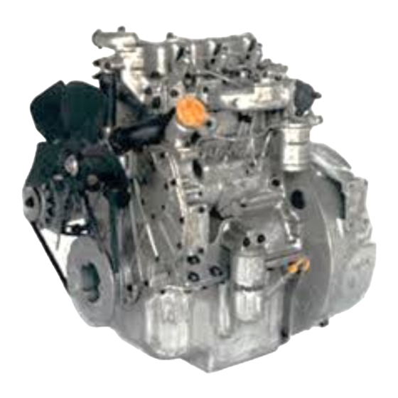
The 3.152 Series is a family of industrial and agricultural engines with power outputs from 24,6 to 41,0 kW
(33.0 to 55.0 bhp). The 3.1524 and T3.1524 are the latest development from Perkins Group Limited, a world
leader in the design and manufacture of high performance diesel engines.
More than fifty years of diesel production experience, together with the latest technology, have been applied
to the manufacture of your engine to give you reliable and economic power.
To ensure that you use the relevant information for your specific engine type, refer to
"Engine identification"
on page
9.
User's Handbook, TPD 1285E, Issue 2
1
This document has been printed from SPI². Not for Resale
Advertisement
Table of Contents

Subscribe to Our Youtube Channel
Related Manuals for Perkins 3.152 Series


Summary of Contents for Perkins 3.152 Series
- Page 1 General information Introduction The 3.152 Series is a family of industrial and agricultural engines with power outputs from 24,6 to 41,0 kW (33.0 to 55.0 bhp). The 3.1524 and T3.1524 are the latest development from Perkins Group Limited, a world leader in the design and manufacture of high performance diesel engines.
-
Page 2: Safety Precautions
Never allow this burnt material to come into contact with the skin or with the eyes. Fit only genuine Perkins parts. User’s Handbook, TPD 1285E, Issue 2 This document has been printed from SPI². Not for Resale... -
Page 3: How To Care For Your Engine
Renew the filter elements and lubricating oil regularly in order to ensure that the inside of your engine remains clean. Ensure that all adjustments and repairs are done by personnel who have had the correct training Perkins distributors have this type of personnel available. You can also obtain parts and service from your Perkins distributor. -
Page 4: Engine Preservation
Warning! Certain corrosion inhibitor mixtures could cause damage to some engine components. It is recommended that you consult the Service Department, Perkins International Limited, Peterborough if a corrosion inhibitor is to be used. 7 Operate the engine for a short period in order to circulate the lubricating oil and the coolant in the engine. - Page 5 If the engine protection is done correctly according to the above recommendations, no corrosion damage will normally occur. Perkins are not responsible for damage which may occur when an engine is in storage after a period in service.
-
Page 6: Parts And Service
Parts and service If problems occur with your engine or with the components fitted onto it, your Perkins distributor can make the necessary repairs and will ensure that only the correct parts are fitted and that the work is done correctly. - Page 7 3.152 POWERPART Liquid gasket To seal flat faces of components where no joint is used. Especially suitable for aluminium components. Currently Loctite 518. Part number 21820518. POWERPART Threadlock (hydraulic/pneumatic) To retain and seal pipe connections with fine threads. Especially suitable for hydraulic and pneumatic systems. Currently Loctite 542.
-
Page 8: Service Literature
Local training for the correct operation, service and overhaul of engines is available at certain Perkins distributors. If special training is necessary, your Perkins distributor can advise you how to obtain it at the Perkins Product Education Department, Peterborough, or other main centres. -
Page 9: Engine Identification
3.152 Engine identification The 3.152 Series family consists of three engines; the naturally aspirated D3.152 and 3.1524 and the turbocharged T3.1524. The engine number is stamped on the left or right side of the cylinder block (A1). An example of an engine number is CM33625U927520Y. -
Page 10: Engine Data
3.152 Engine data Number of cylinders - D3.152 ........................3 - 3.1524, T3.1524... -
Page 11: Location Of Engine Parts
3.152 Engine views Introduction Perkins engines are built for specific applications and the views which follow do not necessarily match your engine specification. Location of engine parts Front and left side of T3.1524 engine 1 Atomiser 8 Dipstick for lubricating oil... - Page 12 3.152 Rear and right side of T3.1524 engine 14 Water outlet 20 Drain plug for lubricating oil 15 Breather pipe 21 Starter motor 16 Induction manifold 22 Fuel Iift pump 17 Fuelled starting aid 23 Rear lift bracket 18 Alternator 24 Rocker cover 19 Lubricating oil sump User’s Handbook, TPD 1285E, Issue 2...
-
Page 13: How To Start The Engine
Diesel engines need a cold starting aid if they are to start in very cold conditions. Normally, your machine will be fitted with the correct equipment for your region of operation. Perkins engines can be equipped with various cold starting systems. For the 3.152 Series engines these systems are:... -
Page 14: How To Start A Warm Engine
3.152 How to start a warm engine 1 If the engine is equipped with a manual stop control, ensure that it is in the “run” position. 2 Adjust the engine speed control to the quarter open position. 3 Turn the start key to the “HS” or “S” position (A/B) to engage the starter motor. 4 Allow the start key to return to the “R”... - Page 15 3.152 How to start a cold engine without starting aids 1 If the engine is equipped with a manual stop control, ensure that it is in the “run” position. 2 Adjust the engine speed control to the maximum speed position. 3 Turn the start key to the “S”...
-
Page 16: How To Start A Cold Engine With The Fuelled Starting Aid
3.152 How to start a cold engine with the fuelled starting aid 1 If the engine is equipped with a manual stop control, ensure that it is in the “run” position. 2 Turn the start key to the “H” position (A) and keep it there for 15 seconds. 3 Adjust the engine speed control to the maximum speed position. - Page 17 3.152 How to start a cold engine with manually operated start pilot Do not use the hand pump until the starter motor is engaged. The amount of fluid which is necessary for an engine start will be found by experience. 1 If necessary, fill the reservoir with fluid.
- Page 18 3.152 How to start a cold engine with KBi or electrically operated start pilot 1 If necessary, renew the screw type canister. Ensure that the sealing washer remains in position when the new canister is fitted. Each container has a safety valve. 2 If the engine is equipped with a manual stop control, ensure that it is in the “run”...
-
Page 19: How To Stop The Engine
The idle or maximum speed settings must not be changed by the engine operator because this can damage the engine or transmission. The warranty of the engine can be affected if the seals on the fuel injection pump are broken during the warranty period by a person who is not approved by Perkins. Running-in A gradual running-in of a new engine or POWER EXCHANGE engine is not necessary. -
Page 20: Turbocharged Engines
Information for turbocharged engines can be obtained from Perkins. Changes to the settings of the fuel injection pump must be made by a Perkins distributor or by an approved distributor for the fuel injection pump. -
Page 21: Preventive Maintenance Periods
3.152 Preventive maintenance Preventive maintenance periods These preventive maintenance periods apply to average conditions of operation. Check the periods given by the manufacturer of the equipment in which the engine is installed. If necessary, use the shorter periods. When the operation of the engine must conform to the local regulations these periods and procedures may need to be adapted to ensure correct operation of the engine. - Page 22 3.152 Schedules First service at 25/50 hours (All engines) Every 500 hours or 12 months (D3.152) Every day or every 8 hours (All engines) Every 800 hours or 12 months (3.1524, T3.1524) Every 200 hours or 4 months (3.1524, T3.1524) Every 2400 hours (3.1524, T3.1524) Every 250 hours or 4 months (D3.152) Every 2500 hours (D3.152)
-
Page 23: How To Drain The Cooling System
3.152 How to drain the cooling system Warning! Do not drain the coolant while the engine is still hot and the system is under pressure because dangerous coolant can be discharged. 1 Ensure that the machine is on level ground. 2 Remove the filler cap of the cooling system. - Page 24 3.152 How to check the drive belt(s) Renew a belt if it is worn or damaged. If twin belts are fitted, they must be renewed together. To check the deflection, press down the belt with the thumb at the centre of the longest free length and check the deflection (A).
-
Page 25: Fuel Pre-Filter
8 Eliminate the air from the fuel filter, see "How to eliminate air from the fuel system" on page Warning! It is important to use only genuine Perkins fuel filter element. The use of the wrong element can damage the fuel injector pump. -
Page 26: Atomiser Fault
3.152 Atomiser fault Warnings! Ensure that the fuel does not spray onto your skin. Keep away from moving parts during engine operation. Some moving parts cannot be seen clearly while the engine runs. An atomiser fault can cause an engine misfire. In order to find which atomiser is defective, operate the engine at a fast idle speed. -
Page 27: How To Eliminate Air From The Fuel System
3.152 How to eliminate air from the fuel system There are two methods to eliminate air from the fuel system according to the type of pump fitted: Standard method: This method is used on the Lucas DPA fuel injection pump. Vent screws (A1 and A2) are fitted to this pump. - Page 28 3.152 Standard method to eliminate air from the fuel system 1 Loosen the banjo connection bolt which is fitted on the top of the filter (A1). 2 Operate the priming lever on the fuel lift pump (B) until fuel, free from air, comes from the filter vent point. Tighten the banjo connection bolt.
- Page 29 3.152 7 Loosen the union nut (D1) at the fuelled starting aid (if one is fitted) and operate the lift pump until fuel, free from air, comes from the connection. Tighten the union nut at the starting aid. 8 Loosen the union nuts of the high-pressure pipes (E1) at two of the atomisers. Operate the starter motor until fuel, free from air, comes from the pipe connections.
- Page 30 3.152 Self-vent method to eliminate air from the fuel system If the engine has been stopped by air in the fuel system: Ensure that fuel has been added to the tank or that the leakage has been corrected. 1 If a manual stop control is fitted, ensure that it is in the “run” position. 2 Operate the starter motor until the engine starts.
-
Page 31: How To Renew The Lubricating Oil
3.152 How to renew the lubricating oil 1 Operate the engine until it is warm. 2 Stop the engine, remove the sump drain plug (A1) and its washer and drain the lubricating oil from the sump. Fit the drain plug and a new washer and tighten the plug to 34 Nm (25 Ibf ft) 3,5 kgf m. 3 Fill the sump to the mark on the dipstick (B1) with new and clean lubricating oil of an approved grade, see "Lubricating oil specification"... -
Page 32: How To Renew The Canister Of The Lubricating Oil Filter
Warning! The canister contains a valve and special tube to ensure that lubricating oil does not drain from the filter. Therefore, ensure that the correct Perkins POWERPART canister is used. User’s Handbook, TPD 1285E, Issue 2... -
Page 33: Air Cleaner
3.152 Air cleaner A typical wet type air cleaner is shown at (A). The wet type air cleaner must be drained at a suitable interval. The container and element (A1) must be cleaned with kerosene or with another suitable fluid. Do not use gasolene. Check that the seal (A2) is not damaged and renew it, if necessary. -
Page 34: Air Filter
3.152 Air filter Environmental conditions have an important effect on the frequency at which the air filter needs service. Certain air filters have a separate dust bowl (A1) which must be cleaned at intervals. The amount of dust in the bowl shows if it has been removed at the correct time for the conditions of operation. -
Page 35: Restriction Indicator
3.152 Restriction indicator The restriction indicator for these engines must work at a pressure difference of 381/457 mm (15/18 in) of water gauge. It is fitted on the air filter outlet or between the air filter and the induction manifold. When the red warning indicator (A1) is seen through the clear panel (A2) after the engine has stopped, the air filter element must be removed for service. - Page 36 3.152 How to check the tappet clearances These are checked between the top of the tappet and the rocker lever (A1). For D3.152 engines the correct clearances are 0,30 mm (0.012 in) for inlet and exhaust valves with the engine cold. For 3.1524 and T3.1524 engines the correct clearances are 0,20 mm (0.008 in) for the inlet valves and 0,32 mm (0.0125 in) for the exhaust valves with the engine hot or cold.
-
Page 37: Engine Fluids
These fuels can be used but they can affect engine performance. It is recommended that you consult the Perkins Technical Service Department at Peterborough, especially if JP4 fuel is to be used. These fuels are more flammable than diesel fuel and need careful storage and careful management. -
Page 38: Lubricating Oil Specification
3.152 Lubricating oil specification Use only a good quality lubricating oil to the relevant specification as shown in the table below. Specifications Engine type API CC ACEA E1 API CD Naturally aspirated Naturally aspirated engines in heavy duty earth moving equipment Turbocharged (1) Not recommended for the first 25/50 hours of operation, nor for light load applications. -
Page 39: Coolant Specification
1 If it is possible, use clean soft water in the coolant. 2 If an antifreeze mixture, other than Perkins POWERPART, is used to prevent frost damage, it must have an ethanediol base (ethylene glycol) with a corrosion inhibitor. It is recommended that the corrosion inhibitor is of the sodium nitrite or sodium benzoate type. - Page 40 This page is intentionally blank This document has been printed from SPI². Not for Resale...
-
Page 41: Fault Diagnosis
3.152 Fault diagnosis Problems and possible causes Possible causes Engine problem Checks by the Checks by the user workshop personnel The starter motor turns the engine too slowly 1, 2, 3, 4 5, 6, 7, 8, 9, 10, 12, 13, 14, 15, The engine does not start 34, 35, 36, 37, 38, 42, 43, 44 5, 7, 8, 9, 10, 11, 12, 13, 14, 15,... - Page 42 3.152 Code list of possible causes 1 Battery capacity low. 2 Bad electrical connections. 3 Fault in starter motor. 4 Wrong grade of lubricating oil. 5 Starter motor turns engine too slowly. 6 Fuel tank empty. 7 Fault in stop control. 8 Restriction in a fuel pipe 9 Fault in fuel lift pump.
- Page 43 3.152 47 Lubricating oil pump is worn. 48 Relief valve does not close. 49 Relief valve does not open. 50 Relief valve spring is broken. 51 Fault in suction pipe of lubricating oil pump. 52 Piston is damaged. 53 Piston height is incorrect. 54 Flywheel housing or flywheel is not aligned correctly.
- Page 44 This page is intentionally blank This document has been printed from SPI². Not for Resale...
Need help?
Do you have a question about the 3.152 Series and is the answer not in the manual?
Questions and answers