
Related Manuals for Heartway Medical Products S12


Summary of Contents for Heartway Medical Products S12
- Page 1 USERS MANUAL HEARTWAY MEDICAL PRODUCTS CO., LTD. NO. 6, ROAD 25, TAICHUNG INDUSTRIAL PARK, TAICHUNG. TAIWAN R.O.C.408 PUBLISHED: AUG. 3, 2009 VERSION: 1 Part no:70030175...
-
Page 2: Table Of Contents
CONTENTS 1. Te c h n i c a l S p e c i f i c a t i o n … … … … … ......... . . … … … … … . 3 2. -
Page 3: Te C H N I C A L S P E C I F I C A T I O N
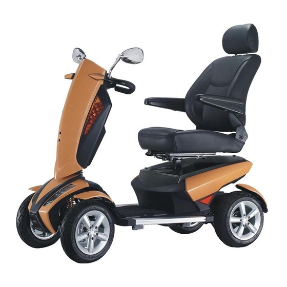
TECHNICAL SPECIFICATIONS MODEL WEIGHT CAPACITY 160kgs(350 lbs) SEAT: TYPE/SIZE 20" A2 DRIVE WHEEL 330mmx120mm(13" x 5") FRONT CASTER (WHEEL) 330mmx100mm(13" x 3.5") REAR CASTER (ANTI-TIPPER) None MAX SPEED 15KPH (9.3MPH); Opt: 20KPH (12.4MPH) BATTERY SPECIFICATIONS 12V 62Ah x 2pcs; Opt:80Ah BATTERY RANGE 45km CHARGER TYPE... -
Page 4: Safety Instruction
SAFETY INSTRUCTION OPERATION OF SCOOTER To prevent injury to yourself or others, always ensure that the power is switched off when getting on or off of the scooter. Always check that the drive wheels are engaged (drive mode) before driving. Engaged Free Wheel (Fig.1) - Page 5 General Always use a seat belt, and keep your feet on the scooter all the time. Do not over load the scooter with it’s maximum weight capacity of 160 kg (350 lbs) Do not attempt to lift or move a power scooter by any of its removable parts. Personal injury and damage to the power chair may result.
- Page 6 The United States Food and drug Administration (FDA) suggests that the following statement be incorporated to the user’s manual for all power scooter like the S12. Power wheelchairs and motorized scooters (in this section, both will be referred to as powered wheelchairs) may as...
- Page 7 TURN OFF YOUR POWERED SCOOTER AS SOON AS POSSIBLE WHEN EXPERIENCING THE FOLLOWING: ‧ Unintentional scooter movements ‧ Unintended or uncontrollable direction. ‧ Unexpected brake release The FDA has written to the manufacturers of power scooters asking them to test new products to be sure they provide a reasonable degree of immunity against EMI.
- Page 8 ENVIRONMENTAL CONDITIONS Environmental conditions may affect the safety and performance of your power scooter. Water and extreme temperatures are the main elements that can cause damage and affect performance. A) Rain, Sleet and Snow If exposed to water, your power scooter is susceptible to damage to electronic or mechanical components.
-
Page 9: Warranty
WARRANTY Quality/ Warranty Declaration Products are to be fit for purpose and of excellent quality and performance. For valid warranty claims Heartway will, at their discretion, replace/ repair/ refund items mutually agreed to be defective. Heartway’s warranty as following: (1) Frame: two year limited warranty (2) Electronic Components and Charger: one year limited warranty. -
Page 10: A S S E M B L Y I N S T R U C T I O
ASSEMBLY INSTRUCTION It is very easy to assemble your S12 scooter. Please follow the procedure below. Installing the Batteries: Remove three screws as shown on (Fig.4) and take off the cover. Connect both battery cables probably (﹢/ ﹣pole ,Red is positive, black is negative) Connected (Fig.4) - Page 11 2.1 Seat Rotation → Press the seat swivel lever downward. → Rotate your seat by clockwise or counter-clockwise direction. (Fig.7) (Fig.8) 2.2 Seat Position Adjustment → Push the seat adjust lever upwards. → Move the seat to your desired position →...
- Page 12 2.4Tiller Positioning Press down the lever and move it to your preferred position. (See Fig 10 & 11) (Fig.10) (Fig.11) 2.6 The adjustment of the suspension system: The softness of the rear suspension system can be adjustable. There are altogether 5 stages of adjustment. Tooling bar...
- Page 13 OPERATION AND CONTROL PANEL SCOOTER CONTROL PANEL (LCD) SPECIFICATION FOR :S12 PREPD TEST DESN APPR NAME: SCOOTER CONTROL PANEL DWG NO: REVISION RECORD DATE PREP...
-
Page 14: C O N T R O L P A N E L L A Y O U
Control Panel Layout LCD(Liquid Crystal Display)Power Scooter Control Panel, TN Type Model LCD(Liquid Crystal Display) Power Indicator:Battery remaining capacity and charging indicator (6 squares + Functions Battery Icon) Clock:Hour / Minute / Second display and setting. Speed Sensor:7 Segment display (2.5 digits +1 decimal) + “km/h / mph” symbol High/Low/ Turn Speed:Indicated as “H”... - Page 15 :Horn :Horn Buttons :Headlight :SET :Back-up Light :MODE Right & Left indicator (Green) ,Parking light (Red),Warning light (Red),Back-up lamps LED Indicators (Yellow),Headlight(Blue)) LCD Backlight LED(White) Connector CON1: 20PIN AMP Usage Condition ITEM SPECIFICATION Voltage DC24 V Operation Voltage DC 16 ~32 V -40℃...
- Page 16 Operating Instruction 1、Speed Sensor and Display ITEM SPECIFICATION Operation Features Speed detection by speed sensor from transaxle with conversion at 1800rpm equal to 60km/h. Tolerance 5~15% (±2%) Digital Range 0.0 ~ 99 Display Switch Button Initial setting at km/h, switch to MPH by MODE buttons 2、High / Low / Turn Speed ITEM...
- Page 17 3、Power Indication ITEM SPECIFICATION Remaining Voltage (V) Scale Bar Capacity (%) > 25.42 ≦ 25.42 ≦ 25.12 Battery Remaining Capacity ≦ 24.78 ≦ 24.42 ≦ 23.88 Flashing Low-power Warning LED Flashing Warning Flicker 2 sec. Frequency (1) Scale status only decrease, won’t increase. Operation (2) When the remaining capacity was less than 30%, warning sound (“Be-Be”...
- Page 18 ITEM SPECIFICATION Remaining Voltage (V) Scale Bar Capacity (%) < 25.44 > 25.44 > 26.18 Charge Indication > 26.92 > 28.5 Increase 0.5 sec. Frequency (1) Scale status only decrease, won’t increase. Operation (2) Take the PIN3(CH3) of charger as determinant signal, enter「Charging Mode」when Character CH3 grounding (L), not only “KEY ON”...
- Page 19 4、Clock Meter ITEM SPECIFICATION Tolerance (per day) ± 2 sec 『Hour:Min』mode :『AM 12:00』 Initial Setting Value 『Hour : Min』 Display range : AM12:00 ~ PM11:59 Setting (12-Hour format) When『Hour』is between 1 and 9 o’clock, displayed at 1~9. 5、Odometer ITEM SPECIFICATION Operation Features Odometer detected by the signal of Opto Coupler then converts into distance.
- Page 20 6、Headlight Control ITEM SPECIFICATION Take exterior headlight switch as determinant signal. Operation Feature (1) Switch on/off the head light by pressing button once, then LED will turn on/off simultaneously. (2) LCD backlights turn on / turn off with head light. When motor stop, the modulation down to 30% (Headlight) Power Saving Mode When motor act, 100% output power (Headlight)
- Page 21 ITEM SPECIFICATION (1) 2.2V>WIP>2.8V ( 50% Half-power ) (2) 2.2V<WIP>2.8V ( 100% Full-power ) Determinant Condition (3) Full / Half power switch at real time. (4) The determination of “Reversing Mode” need to consider the motor direction and panel setting. (1) Loop Load : 24V/50W max Remarks (2) With “short circuit”...
- Page 22 11、Malfunction Message ITEM SPECIFICATION Take the connector pin (KEY) of controller as determinant signal, then converts it into Operation Feature digital code. When the controller send out an error message, red LED flashing with controller signal at same time, the “Error message code” will show on LCD. Usage Condition Flicker Frequency 1 sec.
- Page 23 12、Power on Self-Test ITEM SPECIFICATION When scooter power on, the control panel will go through a self-test routine; the backlight and all LCD segments will be tuned on for 3 seconds, then switch Initial Status automatically to the general operation mode (ODO). 13、Temperature Sensor ITEM SPECIFICATION...
- Page 24 15、Buttons ITEM SPECIFICATION Button “MODE” switch Function set General Display Mode Press SET for 3 seconds to reset TRIP at “00.0”. (TRIP) Press MODE simultaneously for more than 2 seconds. to enter “Setting Mode”, then 『Hour:MIN』start flashing. (1) When『Hour』flashing: Press to increase of number, then press MODE to enter “Setting...
- Page 25 CHARGER Battery Charger Instruction 1. APPEARANCE Power Cord Output Plug to Battery Indicator : Green Flash : Power On Orange Flash : Pre Charge Orange : Charging Green&Orange Flash : Charged Green : Full Charge Red Flash:Defect 2.
-
Page 26: 3.Operating Instruction
3.OPERATING INSTRUCTION (1)Make sure the battery charger output voltage is the same as the connecting battery. (2)Plug in the power cord. LED indicates green flash when AC power on. (3)Connect the battery charger to the battery. (4)Start charging; please refer to 4. LED INDICATION 4.LED INDICATION (1)Green Flash:Power on (2)Orange:Charging... - Page 27 Charging Port (Fig 12) Important! →Always charge your batteries in well ventilated areas. →The charger is intended for indoor use only. Protect from moisture. →For maximum performance, it is recommended that you replace both batteries at the same time if the batteries are weak. →If the scooter will not be used for a long period of time, arrange to have the batteries recharge at least once every month to avoid deterioration of the batteries.
-
Page 28: Maintenance And Repair
MAINTENANCE & REPAIR Your power scooter is designed for minimal maintenance. However, like any motorized vehicle it requires routine maintenance. To keep your PF6 for years of trouble-free operation, we recommend you follow the following maintenance checks as scheduled. DAILY CHECKS 1. -
Page 29: C H E C K
CHECKS Make sure to keep the controller clean while protecting it from rain or water. Never hose off your power scooter or place it in direct contact with water. Keep wheels free from lint, hair, sand and carpet fibers. Visually inspect the tire tread. If less than 1mm(1/32”), please have your tyres replaced by your local dealer. - Page 30 for a few minutes, and then turn the power back on again. The controller has detected a shorted motor. Check the loom for shorts and check the motor. Contact your service agent. Brake fault Drive Check that the park brake release lever is in the inhibited engaged position .
-
Page 31: Circuit Diagram
Circuit Diagram HEARTWAY’s Patent A brand new double-A arms suspension system. -
Page 32: Bom List Drawing
BOM List Drawing...
Need help?
Do you have a question about the S12 and is the answer not in the manual?
Questions and answers