
Related Manuals for Nilfisk-Advance Micromatic M17B


Summary of Contents for Nilfisk-Advance Micromatic M17B
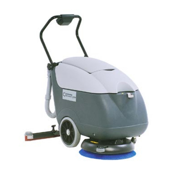
- Page 1 Micromatic M17B Micromatic M17E SERVICE MANUAL Advance model: 908 7057 020 908 7058 020 9097091000(1)2007-06...
- Page 2 ENGLISH SERVICE MANUAL Micromatic M17B - Micromatic M17E 9097091000(1)2007-06...
-
Page 3: Table Of Contents
TROUBLESHOOTING [MICROMATIC M17E] ....................22 RECOVERY WATER SYSTEM ..........................23 TANK AND VACUUM GRID WITH FLOAT CLEANING [MICROMATIC M17B - MICROMATIC M17E] ....23 VACUUM SYSTEM MOTOR ELECTRICAL INPUT CHECK [MICROMATIC M17B - MICROMATIC M17E] ..24 VACUUM SYSTEM MOTOR CARBON BRUSH CHECK AND REPLACEMENT [MICROMATIC M17B - MICROMATIC M17E] ..................... -
Page 4: General Information
MICROMATIC M17E Spare Parts List - Form Number 909 5856 000 MICROMATIC M17B - MICROMATIC M17E Installation instruction curved squeegee kit - Form Number 909 5917 000 MICROMATIC M17B - MICROMATIC M17E Installation instruction shock absorber kit - Form Number 909 6227 000 SAFETY Advance uses the following symbols to indicate potentially dangerous situations. -
Page 5: General Safety Precautions
Do not wear jewerly when working near electrical components. – Do not operate the machine near toxic, dangerous, inflammable and/or explosive powders, fluids or vapors. WARNING! [MICROMATIC M17B - MICROMATIC M17E] – Carefully read all the instructions before carrying out any maintenance/repair procedure. –... - Page 6 ENGLISH SERVICE MANUAL GENERAL INFORMATION WARNING! [MICROMATIC M17B] – Before connecting the battery charger to the electrical mains, be sure that frequency and voltage indicated in the Manual are compatible with the mains voltage. – When using lead (WET) batteries, do not smoke while charging the batteries.
-
Page 7: Technical Data
SERVICE MANUAL ENGLISH GENERAL INFORMATION TECHNICAL DATA General MICROMATIC M17B MICROMATIC M17E Cleaning width 17.0 in (430 mm) Machine width (without squeegee) 22.4 in (570 mm) Minimum machine length with adjustable handlebar 39.2 in (997 mm) Minimum machine height with adjustable handlebar 28.7 - 32.9 in (730 - 836 mm) -
Page 8: Maintenance
Provided below is the Scheduled Maintenance Table. The intervals shown may vary according to particular working conditions, which are to be defined by the person in charge of the maintenance. For instructions on maintenance procedures, see the following paragraphs. SCHEDULED MAINTENANCE TABLE [MICROMATIC M17B] Daily or after Every six... -
Page 9: Machine Nomenclature
Recovery water drain hose bracket [E] Terminal board box Solution drain valve Squeegee lifting/lowering lever Solution filter [B]: Installed on MICROMATIC M17B [S] Battery charger-electrical mains connecting cable [E]: Installed MICROMATIC M17E [E] Power supply cable Squeegee vacuum hose Transport/parking device 30a. - Page 10 ENGLISH SERVICE MANUAL GENERAL INFORMATION [MICROMATIC M17B] 16 15 14 13 21 17 19 20 S301204 9097091000(1)2007-06 Micromatic M17B - Micromatic M17E...
- Page 11 SERVICE MANUAL ENGLISH GENERAL INFORMATION [MICROMATIC M17B] S301205 Micromatic M17B - Micromatic M17E 9097091000(1)2007-06...
- Page 12 ENGLISH SERVICE MANUAL GENERAL INFORMATION [MICROMATIC M17E] S301206 9097091000(1)2007-06 Micromatic M17B - Micromatic M17E...
- Page 13 SERVICE MANUAL ENGLISH GENERAL INFORMATION [MICROMATIC M17E] S301207 Micromatic M17B - Micromatic M17E 9097091000(1)2007-06...
-
Page 14: Solution System
SERVICE MANUAL SOLUTION SYSTEM SOLUTION SYSTEM SOLUTION TANK CLEANING [MICROMATIC M17B - MICROMATIC M17E] Drive the machine to the appointed disposal area. Check that the switches (5 and 6) are turned to “0”. If necessary, empty the tank (44) by means of the valve (24). -
Page 15: Solution Flow Control Tap Or Solenoid Valve Disassembly/Assembly [Micromatic M17B - Micromatic M17E]
SERVICE MANUAL ENGLISH SOLUTION SYSTEM SOLUTION FLOW CONTROL TAP OR SOLENOID VALVE DISASSEMBLY/ASSEMBLY [MICROMATIC M17B - MICROMATIC M17E] Preliminary procedures Remove the batteries. Use a protection to avoid damaging the machine and tilt it carefully to lay its right side on the floor. Solenoid valve disassembly Remove the screw (B) and disconnect the solenoid valve connector (C). -
Page 16: Troubleshooting [Micromatic M17B - Micromatic M17E]
ENGLISH SERVICE MANUAL SOLUTION SYSTEM TROUBLESHOOTING [MICROMATIC M17B - MICROMATIC M17E] SMALL AMOUNT OF THE SOLUTION OR NO SOLUTION REACHES THE BRUSH Possible causes: The solution filter is clogged/dirty (clean). The solution flow adjusting tap is clogged/dirty (replace). The solenoid valve is broken or there is an open in the electrical connection (replace the solenoid valve/repair the electrical connection). -
Page 17: Brushing System
SERVICE MANUAL ENGLISH BRUSHING SYSTEM BRUSHING SYSTEM BRUSH MOTOR ELECTRICAL INPUT CHECK [MICROMATIC M17B] WARNING! This procedure must be performed by qualified personnel only. Check that the brush (54) is installed on the machine. Drive the machine on a level ground. - Page 18 ENGLISH SERVICE MANUAL BRUSHING SYSTEM S301211 9097091000(1)2007-06 Micromatic M17B - Micromatic M17E...
-
Page 19: Brush Motor Electrical Input Check [Micromatic M17E]
SERVICE MANUAL ENGLISH BRUSHING SYSTEM BRUSH MOTOR ELECTRICAL INPUT CHECK [MICROMATIC M17E] WARNING! This procedure must be performed by qualified personnel only. Check that the brush (A) is installed on the machine. Drive the machine on a level ground. Check that the switches (5 and 6) are turned to “0”. If there is recovery water in the tank (43), drain it through the hose (22). - Page 20 SERVICE MANUAL BRUSHING SYSTEM S301210 BRUSH MOTOR CARBON BRUSH CHECK AND REPLACEMENT [MICROMATIC M17B] (for machines before 2007/05) Remove the brush/pad-holder deck (see the procedure in the relevant paragraph). At the workbench, remove dust and dirt from the outside of the motor, then disengage and remove the clamp (A).
-
Page 21: Brush Motor Carbon Brush Check And Replacement [Micromatic M17B]
SERVICE MANUAL ENGLISH BRUSHING SYSTEM BRUSH MOTOR CARBON BRUSH CHECK AND REPLACEMENT [MICROMATIC M17B] (for machines after 2007/05) Remove the brush/pad-holder deck (see the procedure in the relevant paragraph). At the workbench, remove dust and debris from the motor, especially in the area of the carbon brushes. -
Page 22: Brush Motor And Reduction Unit Disassembly/Assembly [Micromatic M17B]
ENGLISH SERVICE MANUAL BRUSHING SYSTEM BRUSH MOTOR AND REDUCTION UNIT DISASSEMBLY/ASSEMBLY [MICROMATIC M17B] Motor/reduction unit disassembly/assembly Remove the brush/pad-holder (54/55), according to the instructions in the Instructions for Use Manual. Remove the brush/pad-holder deck. At the workbench, remove the central screw (A). -
Page 23: Brush Motor And Reduction Unit Disassembly/Assembly [Micromatic M17E]
SERVICE MANUAL ENGLISH BRUSHING SYSTEM BRUSH MOTOR AND REDUCTION UNIT DISASSEMBLY/ASSEMBLY [MICROMATIC M17E] Motor/reduction unit disassembly/assembly Remove the brush/pad-holder (54/55), according to the instructions in the Instructions for Use Manual. Remove the brush/pad-holder deck. At the workbench, remove the central screw (A). Remove the polygonal support (B). -
Page 24: Troubleshooting [Micromatic M17B]
ENGLISH SERVICE MANUAL BRUSHING SYSTEM TROUBLESHOOTING [MICROMATIC M17B] OPEN CIRCUIT The brush motor fuse F1 determines the open circuit. This system allows to prevent the brush motor and circuits from being damaged under overload conditions. If there is an open in the circuit, the possible causes are: Bulky debris or cords around the brush or between the brush and its flange (remove the brush and the debris or cords). -
Page 25: Recovery Water System
ENGLISH RECOVERY WATER SYSTEM RECOVERY WATER SYSTEM TANK AND VACUUM GRID WITH FLOAT CLEANING [MICROMATIC M17B - MICROMATIC M17E] Drive the machine to the appointed disposal area. Check that the switches (5 and 6) are turned to “0”. If necessary, empty the tank (43) by means of the hose (22). -
Page 26: Vacuum System Motor Electrical Input Check [Micromatic M17B - Micromatic M17E]
ENGLISH SERVICE MANUAL RECOVERY WATER SYSTEM VACUUM SYSTEM MOTOR ELECTRICAL INPUT CHECK [MICROMATIC M17B - MICROMATIC M17E] WARNING! This procedure must be performed by qualified personnel only. Drive the machine on a level ground. Check that the switches (5 and 6) are turned to “0”. - Page 27 SERVICE MANUAL ENGLISH RECOVERY WATER SYSTEM S301373A S301216 [The figure shows MICROMATIC M17E] Micromatic M17B - Micromatic M17E 9097091000(1)2007-06...
-
Page 28: Vacuum System Motor Carbon Brush Check And Replacement [Micromatic M17B - Micromatic M17E]
ENGLISH SERVICE MANUAL RECOVERY WATER SYSTEM VACUUM SYSTEM MOTOR CARBON BRUSH CHECK AND REPLACEMENT [MICROMATIC M17B - MICROMATIC M17E] Remove the vacuum system motor (see the procedure in the relevant paragraph). At the workbench, disengage the fasteners (A) and (B), then remove the cover (C) from the vacuum system motor. -
Page 29: Vacuum System Motor Disassembly/Assembly [Micromatic M17B - Micromatic M17E]
SERVICE MANUAL ENGLISH RECOVERY WATER SYSTEM VACUUM SYSTEM MOTOR DISASSEMBLY/ASSEMBLY [MICROMATIC M17B - MICROMATIC M17E] Check that the switches (5 and 6) are turned to “0”. If there is recovery water in the tank (43), drain it through the hose (22). -
Page 30: Squeegee Disassembly/Assembly [Micromatic M17B - Micromatic M17E]
Disconnect the vacuum hose (29) from the squeegee. Loosen the handwheels (18) and remove the squeegee (17). Assemble in the reverse order of disassembly. SQUEEGEE CLEANING/CHECK AND BLADE REPLACEMENT [MICROMATIC M17B - MICROMATIC M17E] CAUTION! It is advisable to use protective gloves when cleaning the squeegee because there may be cutting debris. -
Page 31: Troubleshooting [Micromatic M17B]
If there is an open in the circuit, the possible causes are: The motor is damaged (check the motor carbon brushes/electrical input). The electrical input is excessive (check the motor for proper rotation). TROUBLESHOOTING [MICROMATIC M17B - MICROMATIC M17E] DIRTY WATER VACUUMING IS INSUFFICIENT OR THERE IS NO VACUUMING Possible causes: The vacuum grid with automatic shut-off float (46) is activated because the water recovery tank (43) is full (empty the water recovery tank). -
Page 32: Other Systems
SERVICE MANUAL OTHER SYSTEMS OTHER SYSTEMS MACHINE SPEED ADJUSTMENT [MICROMATIC M17B - MICROMATIC M17E] Check that the switches (5 and 6) are turned to “0”. If there is recovery water in the tank (43), drain it through the hose (22). -
Page 33: Brush/Pad-Holder Deck Disassembly/Assembly [Micromatic M17B]
SERVICE MANUAL ENGLISH OTHER SYSTEMS BRUSH/PAD-HOLDER DECK DISASSEMBLY/ASSEMBLY [MICROMATIC M17B] Disassembly Remove the batteries. Remove the caps (A) and disconnect the electrical connections from the brush motor (B). Remove the left deck fastening screw (58). Use a protection (D) to avoid damaging the machine and tilt it carefully to lay its left side on the floor. -
Page 34: Brush/Pad-Holder Deck Disassembly/Assembly [Micromatic M17E]
ENGLISH SERVICE MANUAL OTHER SYSTEMS BRUSH/PAD-HOLDER DECK DISASSEMBLY/ASSEMBLY [MICROMATIC M17E] Disassembly Check that the switches (5 and 6) are turned to “0”. If there is recovery water in the tank (43), drain it through the hose (22). Disconnect the vacuum hose (29) from the squeegee (17). Open the cover (12). - Page 35 SERVICE MANUAL ENGLISH OTHER SYSTEMS S301377A S301222 Micromatic M17B - Micromatic M17E 9097091000(1)2007-06...
-
Page 36: Electrical System
SERVICE MANUAL ELECTRICAL SYSTEM ELECTRICAL SYSTEM (WET OR GEL) BATTERY REMOVAL/INSTALLATION AND SETTING [MICROMATIC M17B] Disassembly Check that the switches (5 and 6) are turned to “0”. If there is recovery water in the tank (43), drain it through the hose (22). -
Page 37: Charging Curves Setting [Micromatic M17B]
ELECTRICAL SYSTEM S301223 CHARGING CURVES SETTING [MICROMATIC M17B] (for machines starting S/N .....) Remove the plastic cap (A) in order to access to the internal DIP SWITCH. With a small screwdriver change the DIP SWICH in accordance with the below listed setting data. -
Page 38: Battery Charging [Micromatic M17B]
ENGLISH SERVICE MANUAL ELECTRICAL SYSTEM BATTERY CHARGING [MICROMATIC M17B] NOTE Charge the batteries when the warning light (3) or (4) turns on, or when finishing cleaning. Keeping the batteries charged makes them last longer. CAUTION! When the batteries are discharged, charge them as soon as possible, as that condition makes them last shorter. - Page 39 SERVICE MANUAL ENGLISH ELECTRICAL SYSTEM Battery charging with battery charger installed on the machine Connect the battery charger cable (27) to the electrical mains (the mains voltage and frequency must be compatible with the battery charger values: see the battery charger Manual). NOTE When the battery charger is connected to the electrical mains, all machine functions are automatically cut off.
-
Page 40: Electronic Board Replacement [Micromatic M17B]
ENGLISH SERVICE MANUAL ELECTRICAL SYSTEM ELECTRONIC BOARD REPLACEMENT [MICROMATIC M17B] Check that the switches (5 and 6) are turned to “0”. Remove the recovery water tank and disconnect the battery negative terminal (50) according to the following procedure: • If there is recovery water in the tank (43), drain it through the hose (22). - Page 41 SERVICE MANUAL ENGLISH ELECTRICAL SYSTEM S301224 Micromatic M17B - Micromatic M17E 9097091000(1)2007-06...
-
Page 42: Fuse Check/Replacement [Micromatic M17B]
ENGLISH SERVICE MANUAL ELECTRICAL SYSTEM FUSE CHECK/REPLACEMENT [MICROMATIC M17B] Check that the switches (5 and 6) are turned to “0”. Remove the recovery water tank and disconnect the battery negative terminal (50) according to the following procedure: • If there is recovery water in the tank (43), drain it through the hose (22). - Page 43 SERVICE MANUAL ENGLISH ELECTRICAL SYSTEM S301225 Micromatic M17B - Micromatic M17E 9097091000(1)2007-06...
-
Page 44: Component Location [Micromatic M17B]
ENGLISH SERVICE MANUAL ELECTRICAL SYSTEM COMPONENT LOCATION [MICROMATIC M17B] CH1: Battery charger Battery charger connector EB1: Electronic board (CF BA430) EB2: Electronic board led (CF BALED) ES1: Brush switch ES2: Vacuum switch EV1: Water solenoid valve Brush fuse (40A) Vacuum system fuse (30A) - Page 45 SERVICE MANUAL ENGLISH ELECTRICAL SYSTEM S301227 Micromatic M17B - Micromatic M17E 9097091000(1)2007-06...
-
Page 46: Component Location [Micromatic M17E]
ENGLISH SERVICE MANUAL ELECTRICAL SYSTEM COMPONENT LOCATION [MICROMATIC M17E] EV1: Solenoid valve Frame Brush/pad motor Vacuum system motor Plug SW1: Brush/pad switch SW2: Vacuum switch M2-C1 S301228 9097091000(1)2007-06 Micromatic M17B - Micromatic M17E... -
Page 47: Wiring Diagram [Micromatic M17B]
SERVICE MANUAL ENGLISH ELECTRICAL SYSTEM WIRING DIAGRAM [MICROMATIC M17B] (for machines before 2007/05) Key: CH1: Battery charger Battery charger connector EB1: Electronic board EB2: Electronic board LED (CF BALED) ES1: Brush switch ES2: Vacuum switch ES3: Battery charger realay EV1:... -
Page 48: Wiring Diagram [Micromatic M17E]
ENGLISH SERVICE MANUAL ELECTRICAL SYSTEM WIRING DIAGRAM [MICROMATIC M17B] (for machines before 2007/05) (continues) NO Ch Pb/Gel SWITCH CFBA430 BU BN OR WH S301229 9097091000(1)2007-06 Micromatic M17B - Micromatic M17E... - Page 49 SERVICE MANUAL ENGLISH ELECTRICAL SYSTEM WIRING DIAGRAM [MICROMATIC M17B] (for machines after 2007/05) Key: CH1: Battery charger Battery charger connector EB1: Electronic board EB2: Electronic board LED (CF BALED) ES1: Brush switch ES2: Vacuum switch EV1: Water solenoid valve Brush fuse (40A)
- Page 50 ENGLISH SERVICE MANUAL ELECTRICAL SYSTEM WIRING DIAGRAM [MICROMATIC M17B] (for machines after 2007/05) (continues) NO Ch Pb/Gel SWITCH CFBA430 BU BN OR WH S301229A 9097091000(1)2007-06 Micromatic M17B - Micromatic M17E...
- Page 51 SERVICE MANUAL ENGLISH ELECTRICAL SYSTEM WIRING DIAGRAM [MICROMATIC M17E] Key: EV1: Solenoid valve Frame Brush/pad motor Vacuum system motor Plug SW1: Brush/pad switch SW2: Vacuum switch Colour code Black Blue Brown Green Grey Orange Pink Violet White Yellow BN(3) BU(4) BK(1) YE-GN YE-GN...
- Page 52 Nilfisk-Advance, Inc. 14600 21st Avenue North Plymouth, MN, 55447-3408 www.nilfisk-advance.com Phone: 800-989-2235 Fax: 800-989-6566 ©2007 Nilfisk-Advance, Inc., Plymouth, MN 55447-3408 Printed in Italy...
Need help?
Do you have a question about the Micromatic M17B and is the answer not in the manual?
Questions and answers