Nilfisk-Advance SC351 Service Manual
Hide thumbs
Also See for SC351:
- Quick start manual ,
- Instructions for use manual (88 pages) ,
- User manual (84 pages)

Related Manuals for Nilfisk-Advance SC351


Summary of Contents for Nilfisk-Advance SC351
-
Page 1: Service Manual
SC351 Service Manual Advance SC351, 9087342020 Nilfisk SC351, 9087340020 - 9087341020 English 2013-05 Form No. 9099876000... -
Page 2: Table Of Contents
Service Manual – SC351 Table of Contents Table of Contents General Information Machine General Description Service Manual Purpose and Field of Application Other Reference Manuals Conventions Service and Spare Parts Serial Number Label Safety Visible Symbols on the Machine Symbols... - Page 3 Service Manual – SC351 Table of Contents Scrub System, Disc Functional Description Wiring Diagram Component Locations Maintenance and Adjustments Troubleshooting Removal and Installation Specifications Solution System Functional Description Wiring Diagram Component Locations Troubleshooting Removal and Installation Specifications Squeegee System Functional Description...
-
Page 4: General Information
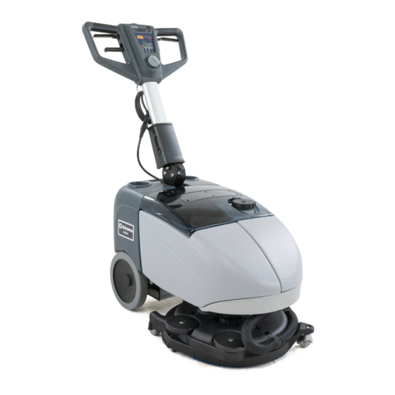
General Information Machine General Description The SC351 is a “walk behind” industrial machine designed to wash and dry floors in one pass. The machine is powered by on-board batteries. The machine is equipped with disc brushes, a controlled solution flow dosing system and a squeegee with blades integrated in the deck, which vacuums and dries the floor. -
Page 5: Conventions
Service Manual – SC351 General Information Conventions Forward, backward, front, rear, left or right are intended with reference to the operator’s position, that is to say in driving position Service and Spare Parts Service and repairs must be performed only by authorised personnel or Advance/Nilfisk Service Centers. The authorised personnel is trained directly at the manufacturer’s premises and has original spare parts and ac-... -
Page 6: Safety
Service Manual – SC351 General Information Safety The following symbols indicate potentially dangerous situations Always read this information carefully and take all necessary precautions to safeguard people and property Visible Symbols on the Machine WARNING! Carefully read all the instructions before performing any operation on the machine. - Page 7 Service Manual – SC351 General Information Caution! Make sure to follow the safety precautions to avoid situations that may lead to serious injuries, damages to materials or equipments. − Carefully read all the instructions before performing any maintenance/repair procedure − Before using the battery charger, ensure that frequency and voltage values, indicated on the machine serial number plate, match the electrical mains voltage −...
-
Page 8: Machine Lifting
Service Manual – SC351 General Information − When using floor cleaning detergents, follow the instructions on the labels of the detergent bot- tles − To handle floor cleaning detergents, wear suitable gloves and protections. − Do not use the machine as a means of transport −... -
Page 9: Machine Nomenclature (Know Your Machine)
Service Manual – SC351 General Information Machine Nomenclature (know your machine) Transparent cover with vacuum grid Handlebar with control panel Vacuum grid with automatic shut-off float Recovery tank Battery Battery charger connection cable holder connector Deck bumper Fuses Can holder... -
Page 10: Control Panel
Service Manual – SC351 General Information Control Panel Program selection knob/rotary switch Scrubbing and drying program: Brush activation Scrubbing program: - Vacuum system activation brush - solution flow activation - Solution flow activation Drying program: Machine switching off “0” brush - vacuum system activation... -
Page 11: Service And Diagnostic Equipment
Service Manual – SC351 General Information Service and Diagnostic Equipment Besides a complete set of standard meters, the following instruments are necessary to perform fast checks and repairs on Nilfisk-Advance machines: • Laptop computer charged with the current version of EzParts, Adobe Reader and (if possible) Internet connection •... -
Page 12: Technical Data
Service Manual – SC351 General Information Technical Data Nilfisk Nilfisk Advance Description SC351 SC351 SC351 full PKG Solution tank capacity 2.9 USgal (11 litres) Recovery tank capacity 2.9 USgal (11 litres) 31.9 in/50 in (810 mm/1,270 mm) Min/max machine length at the handlebar 18.5 in (470 mm) -
Page 13: Dimensions
Service Manual – SC351 General Information Dimensions 17 in - 432 mm 28.5 in - 726 mm 18.7 in - 475 mm P100774... -
Page 14: Maintenance
Service Manual – SC351 General Information Maintenance The lifespan of the machine and its maximum operating safety are ensured by correct and regular mainte- nance Warning! Read carefully the instructions in the Safety chapter before performing any maintenance procedure. The following tables provides the scheduled maintenance The intervals shown may vary according to particu- lar working conditions, which are to be defined by the person in charge of the maintenance. -
Page 15: Chassis System
Service Manual – SC351 Chassis System Chassis System Frame (main parts) Frame Handlebar holder Wheels on fixed axle P100775... -
Page 16: Control System
Service Manual – SC351 Control System Control System Functional Description The function control is performed with the program The LED electronic board (EB1) is equipped with 3 selection knob/rotary switch (SW1), the machine LEDs which indicate the battery charge level, both... -
Page 17: Component Locations
Service Manual – SC351 Control System Component Locations • Handlebar with control panel • Machine start-up enabling push-button (SW2) • Program selection knob/rotary switch (SW1) • Solution flow switch (SW3) • LED electronic board (EB1) • Wiring harness • Brush levers •... -
Page 18: Removal And Installation
Service Manual – SC351 Control System Removal and Installation LED Electronic Board (EB1) Disassembly/Assembly Disconnect the connector (C) of the LED Disassembly electronic board (D) Remove the screws (E) and Drive the machine on a level floor. Make sure remove the LED electronic board (D) - Page 19 Service Manual – SC351 Control System LED Electronic Board (EB1) Disassembly/Assembly (Continues) If necessary, remove the selector assembly (N) of the machine program selection knob (I), as shown below: • Disconnect the connectors (J) • On the outer side, turn the knob (I) on the position (K) (vacuum system activation) •...
- Page 20 Service Manual – SC351 Control System Machine Enabling Push-Button Disassembly/Assembly (SW2) Disassembly Drive the machine on a level floor. Make sure that the machine cannot move independently. Turn the machine program selection knob to “0” Disconnect the battery connector (red)
-
Page 21: Specifications
Service Manual – SC351 Control System Specifications LED electronic board connector (EB1) JA: 4-way vertical Tyco Modu II type Description Electronic board V ref. I max. in/out Common cathode LED power supply <1 A RED anode LED power supply 0.7 V <1 A... -
Page 22: Electrical System
Service Manual – SC351 Electrical System Electrical System Functional Description The program selection knob/rotary switch (SW1) and the machine start-up enabling push-button (SW2) con- trols the vacuum brush motor relay (K1) for the activation of the brush motor (M1) and the vacuum system... -
Page 23: Component Locations
Service Manual – SC351 Electrical System Component Locations • Battery charger (CH) • Vacuum system motor fuse (F2) • 12V Battery (BAT) • Function selector fuse (F3) • Connector (C1) • Brush motor relay (K1) • Battery wiring harness • Solenoid valve timer relay (KT1) •... -
Page 24: Maintenance And Adjustments
Service Manual – SC351 Electrical System Maintenance and Adjustments Battery Installation Open the cover and check that the battery connector is disconnected Install the battery on the machine, connect the terminals and fasten it with the relevant belt Warning! This machine requires sealed lead batteries (GEL or AGM technology). Do not use batteries with liquid electrolyte or not sealed (WET) for any reason. - Page 25 Service Manual – SC351 Electrical System Battery Charger Setting and Dipswitch Configuration To change the dipswitch configuration, remove the round white cap near the openings (see the illustration below), with a screwdriver CBHD2 12V 12A IUIa OPTIMA DIPSWITCH CONFIGURATION P100782...
- Page 26 Service Manual – SC351 Electrical System Fuse Check and Replacement Fuses in the electric component box Drive the machine on a level floor. Check that the function selection knob is turned to “0” and disconnect the battery connector Open the cover and check one of the following fuses for deactivation or integrity: ◦...
-
Page 27: Troubleshooting
Service Manual – SC351 Electrical System Troubleshooting Trouble Possible Causes Remedy The machine is not working The battery connector (C1) is not connected or broken Connect or replace it The 12V batteries (BAT) are discharged or its connections Charge the batteries or clean/repair the... -
Page 28: General Wiring Diagram
Service Manual – SC351 Electrical System General Wiring Diagram BRUSH MOTOR FUSE (F1) FUNCTION SELECTOR FUSE (F3) VACUUM SYSTEM MOTOR FUSE (F2) PROGRAM SELECTION CONNECTOR (C1) KNOB/ROTARY SWITCH (SW1) BATTERY CHARGER (CH) VACUUM SYSTEM MOTOR RELAY (K2) MACHINE START-UP DIODE (D2) -
Page 29: Specifications
Service Manual – SC351 Electrical System Specifications Nilfisk Nilfisk Advance Description SC351 SC351 SC351 full PKG Total absorbed power 42 A (0.5 kW) Battery compartment size 17.8x6.9x9.4 in (350x175x240 mm) Battery voltage 12 V 12 V 55 AhC20 AGM Standard batteries... -
Page 30: Recovery System
Service Manual – SC351 Recovery System Recovery System Functional Description The water recovery system removes the dirty water from the floor and pipes it to a recovery tank. When the machine is running, the dirty water on the floor is collected by the squeegee blades and collected through the slots in the same, piped through the vacuum hose and into the tank by the airflow created by vacuum motor (M2). -
Page 31: Component Locations
Service Manual – SC351 Recovery System Component Locations • Recovery tank • Squeegee vacuum hose • Vacuum system/tank connection gasket • Vacuum system motor (M2) Recovery tank Squeegee vacuum hose Vacuum system/tank connection gasket Vacuum system motor (M2) P100787... - Page 32 Service Manual – SC351 Recovery System Component Locations (Continues) • Transparent cover • Vacuum system motor fuse (F2) • Vacuum grid with automatic shut-off float • Vacuum system relay (K2) • Cover gasket Vacuum grid with automatic shut-off float Cover gasket...
-
Page 33: Maintenance And Adjustments
Service Manual – SC351 Recovery System Maintenance and Adjustments Tank and Vacuum Grid Cleaning Drive the machine to the appointed disposal area Check that the function selection knob is turned to “0” and disconnect the battery connector Remove the cover (A), clean and wash the cover... - Page 34 Service Manual – SC351 Recovery System Vacuum System Gasket Cleaning Note: The gaskets (L) and (M) create vacuum in the system that is necessary for vacuuming the recovery water. Drive the machine on a level floor. Check that the function selection knob is turned to “0”...
-
Page 35: Troubleshooting
Service Manual – SC351 Recovery System Troubleshooting Trouble Possible Causes Remedy The vacuum system motor (M2) does not The program selection knob/rotary switch (SW1) is Replace. broken. turn on. The vacuum system motor (M2) is faulty. Check the amperage. Replace. - Page 36 Service Manual – SC351 Recovery System Vacuum System Motor Amperage Check Remove the solution and recovery water tanks Apply the amp clamp (A) on the cable (B) Turn the knob on the working program Check that the motor amperage is between 15 and 18 A at 12 V Turn the knob to “0”...
-
Page 37: Removal And Installation
Service Manual – SC351 Recovery System Removal and Installation Vacuum System Motor Disassembly/Assembly Remove the motor (B) and the acoustic Disassembly insulation pipe (G) Remove the solution and recovery water tanks Check the gasket (F) and the gasket (H) for... -
Page 38: Specifications
Service Manual – SC351 Recovery System Specifications Nilfisk Nilfisk Advance Description SC351 SC351 SC351 full PKG Recovery tank capacity 2.9 USgal (11 litres) Vacuum system motor power 0.27 hp (200 W) Vacuuming (with closed inlet) 27.7 in/H O (710 mmH... -
Page 39: Scrub System, Disc
Service Manual – SC351 Scub Sytem - Disc Scrub System, Disc Functional Description The disc brush system can be started by the operator The disc brush turns counter-clockwise The brush system, when turning, cleans/washes the floor surface and assists machine forward movement. -
Page 40: Component Locations
Service Manual – SC351 Scub Sytem - Disc Component Locations • Brush deck • Machine straight forward movement adjusting • Brush motor (M1) handwheel • Drive hub • Deck rotation end of stroke system • Machine forward speed adjusting handwheel... - Page 41 Service Manual – SC351 Scub Sytem - Disc Component Locations (Continues) • Brush motor fuse (F1) • Brush motor relay (K1) Brush motor fuse (F1) Brush motor relay (K1) P100781...
-
Page 42: Maintenance And Adjustments
Service Manual – SC351 Scub Sytem - Disc Maintenance and Adjustments Brush Cleaning Warning! It is advisable to wear protective gloves when cleaning the brush because there may be sharp debris. Remove the brush Clean the brush with water and detergent Check the brush bristles for integrity and wear;... -
Page 43: Troubleshooting
Service Manual – SC351 Scub Sytem - Disc Troubleshooting Open Circuit • The Brush motor fuse (F1) determines an open in the supply circuit of the brush deck motor This protects the circuits from being damaged under overload conditions • The open in the fuse can be caused by the following: •... - Page 44 Service Manual – SC351 Scub Sytem - Disc Brush Motor Amperage Check Drive the machine on a level floor. Turn off the brush by releasing the levers (40) Remove the brush, as shown in the User Turn the knob (32) to “0”...
-
Page 45: Removal And Installation
Service Manual – SC351 Scub Sytem - Disc Removal and Installation Brush Deck Disassembly/Assembly Disassembly Place the machine on a hoisting system (if available), then lift it Otherwise, drive the machine on a level floor. Make sure that the battery connector is... - Page 46 Service Manual – SC351 Scub Sytem - Disc Brush Deck Disassembly/Assembly (Continues) 11 Install the centre flange springs (K) by engaging them on the deck housings and on the centre flange housings (L) as shown in the figure. Assembly 12 Assemble the components in the reverse order of disassembly and note the following: ◦...
- Page 47 Service Manual – SC351 Scub Sytem - Disc Brush Motor Disassembly/Assembly Disassembly Place the machine on a hoisting system (if available), then lift it Otherwise, drive the machine on a level floor. Make sure that the battery connector is disconnected...
-
Page 48: Specifications
Service Manual – SC351 Scub Sytem - Disc Specifications Nilfisk Nilfisk Advance Description SC351 SC351 SC351 full PKG Brush/pad diameter 14.5 in (370 mm) Brush/pad pressure on the floor 39.6 lb (18 Kg) Brush/pad pressure with full tank 59.5 lb (27 Kg) Brush motor power 0.32 hp (240 W) -
Page 49: Solution System
Service Manual – SC351 Solution System Solution System Functional Description The solution system supplies the detergent to the brush when cleaning the floor. The solution tank is also the main machine body There is a manual valve on the left side of the tank to close the water supply whenever maintenance must be performed on the machine The detergent quantity is adjusted by the operator with the solution flow switch (SW3). -
Page 50: Component Locations
Service Manual – SC351 Solution System Component Locations • Solution tank • Solenoid valve (EV) • Filler plug • Detergent hose • Detergent valve Filler plug Solution tank Detergent valve Detergent hose Solenoid valve (EV) P100807... - Page 51 Service Manual – SC351 Solution System Component Locations (Continues) • Solenoid valve timer relay (KT1) Solenoid valve timer relay (KT1) P200067...
-
Page 52: Troubleshooting
Service Manual – SC351 Solution System Troubleshooting Trouble Possible Causes Remedy Small amount of solution or no solution The valve between tank and solution hose is clogged/dirty Clean reaches the brush The solenoid valve (EV) is faulty or the electrical... -
Page 53: Removal And Installation
Service Manual – SC351 Solution System Removal and Installation Solenoid Valve Disassembly/Assembly Remove the screws (D) and recover the washers Disassembly Place the machine on a hoisting system (if Remove the solenoid valve (E) upwards available), then lift it Otherwise, drive the machine on a level floor. -
Page 54: Specifications
Service Manual – SC351 Solution System Specifications Nilfisk Nilfisk Advance Description SC351 SC351 SC351 full PKG Solution tank capacity 2.9 USgal (11 litres) One drop: 0.066 gpm (0.25 litres/min) Min/max solution flow Two drops: 0.13 gpm (0.5 litres/min) Resistance solenoid valve... -
Page 55: Squeegee System
Service Manual – SC351 Squeegee System Squeegee System Functional Description The squeegee system cleans the liquid off the floor, which is then collected by the recovery system. The squeegee is fastened to the brush deck by 2 hooks and the vacuum hose When the machine is running, the conformation of the squeegee and the brush deck rotation mechanism, assist in the alignment and accurate vacuuming of the water from the floor. -
Page 56: Component Locations
Service Manual – SC351 Squeegee System Component Locations • Squeegee • Rear blade • Rear elastic strap • Front blade • Front strap Squeegee Rear blade Rear elastic strap Front blade Front strap P100809... -
Page 57: Maintenance And Adjustments
Service Manual – SC351 Squeegee System Maintenance and Adjustments Squeegee Cleaning Disengage the squeegee (B) from the deck Note: The squeegee must be clean and its blades must be in Wash and clean the squeegee In particular, good conditions in order to clean the compartments (C) and the vacuum get a good drying. - Page 58 Service Manual – SC351 Squeegee System Squeegee Blade Check and Replacement Clean the squeegee as shown in the previous Install the squeegee (B) by carefully inserting paragraph the hooks (L) and the vacuum hole (M) in the brush deck housings...
-
Page 59: Troubleshooting
Service Manual – SC351 Squeegee System Troubleshooting Trouble Possible Causes Remedy Leaving streaks on floor There is debris under the blade Remove The squeegee blade edges are torn or worn Replace... -
Page 60: Wheel System, Non-Traction
Service Manual – SC351 Wheel System, Non-Traction Wheel System, Non-Traction Component Locations • Rear wheels on fixed axle • Castors on brush deck • Rear wheels on brush deck Castors on brush deck Rear wheels on brush deck Rear wheels on fixed... -
Page 61: Specifications
Service Manual – SC351 Wheel System, Non-Traction Specifications Nilfisk Nilfisk Advance Description SC351 SC351 SC351 full PKG Diameter of wheels on fixed axle 8.4 in (214 mm) Wheel pressure on the floor 72.5 psi (0.5 N/mm...
Need help?
Do you have a question about the SC351 and is the answer not in the manual?
Questions and answers